Abstract
The paper focuses on the analysis of sandwich domes using a newly developed doubly curved axisymmetric sandwich finite element. The simple equivalent single layer finite element employs a cubic polynomial approximation for transverse displacement and meridional displacement. The present element accounts for the transverse shear strains of the facing and core using quadratic polynomial. The relation between inplane stresses and strains for axisymmetric deformation has been represented by a state of generalized plane stress. The stiffness matrix has been derived using the variational principle. The numerical examples have been presented to illustrate the element capabilities and accuracy of the results achieved using the newly developed sandwich shell element.
Keywords:
Axisymmetric; Doubly curved; Sandwich shell finite element; Transverse shear strain; Warping; Subsea; Domes
1 INTRODUCTION
The visually appealing dome structures especially roofs have made an everlasting footprint from eternity. The infinite design possibilities, availability of new construction materials and sophisticated computational facilities have made domes one of the prime architectural features of many structures. The domes as roof structures are seen in residential, commercial and religious building. Spherical domes are also used in for covering the quayside storage tanks. The domes can find its application as spherical or geodesic radomes which enclose the radars providing protection from extreme weather. Acoustically transparent and structurally strong and durable sonar domes are made of laminated composites with viscoelastic core and mounted on keel of ships to protect its sonar transducer array. The conceptual gravity based subsea storage unit is also shielded by a dome for storing oils. Pressure hulls of submarines generally appear as cylindrical hulls with spherical, torispherical or hemiellipsoidal dome ends.
Domes being doubly curved membranes are structurally more efficient and economically viable. The aerodynamically efficient thin roof domes make strong structural expression by enclosing large column free space. The domes transfer the load axially and the horizontal loads imposed on domes are resisted by base ring beam thereby reducing the dead weight of the structure and foundation requirements. The spherical dome generates membrane stresses in hoop and meridional direction varying from the apex to the base under gravity loading. The hoop stress is compressive near the crown. The tensile hoop stress at the base is usually resisted by a ring beam or abutment. Domes often appear as structural components of many subsea shells like tethered one atmos chambers, storage structures, inspection modules and submarines. The primary requirement of such shells is to resist the external hydrostatic pressure which induces direct force resultants, but it is generally considered that because of axisymmetric loading and geometry, the membrane shear force and twisting moment vanish. The wide exploration of underwater reaches and tapping of subsea resources can be realised only by newly emerged technologies and construction materials.
The extensive researches have revealed that sandwich constructions can be considered as the most impressive and viable design alternative for deep submergence storage structures (Brink, 1964Brink, N. (1964). Sandwich cylinder construction for underwater pressure vessels, Nav Eng J, 76: 951-954.; Goode and Fatheldin, 1980Goode, C.D. and Fatheldin, Y.T. (1980). Sandwich cylinders (steel-concrete- steel) subjected to external pressure, ACI J, 77: 109-115.) and submarines (Narewski and Rowiñski, 1974Narewski M. and Rowiñski L.A, (1974). Underwater technology developments in ship research institute of technical university of Gdansk.). A comprehensive effort has been made by (Smith, 1991Smith, C.S. (1991). Design of submersible pressure hulls in composite materials, Mar Struct, 4: 141-182.), (Smith et al., 1991Smith, J.R., Graham, D. and Creswell, D.J. (1999). A foam sandwich submarine hull, DERA novel hull model No. 1, In: Proceedings of Warship '99: The International Symposium on Novel Structures, pp. 14-16.), (Liang et al., 2003Liang, C.C, Chen, H.W. and Jen, C.Y. (2003). Optimum design of filament-wound multilayer-sandwich submersible pressure hulls, Ocean Eng, 30: 15: 1941-1967.) and (Lee et al., 2013Lee, G.C., Kweon, J.H. and Choi, J.H. (2013). Optimization of composite sandwich cylinders for underwater vehicle application, Compos Struct, 96: 691-697.) to examine the use of fibre-reinforced polymer composites and sandwich construction in the pressure hulls of submersible vehicles. Sandwich shells are also gaining wide spread acceptance as primary load bearing members in aerospace structures, automobile bodies, subsea applications, naval ship components and wind turbines. A sandwich shell is a special hybrid shell that consists two thin and stiff facings bonded to relatively thick lightweight core. The sandwich configurations have attracted significant interest particularly in underwater applications for their good bending stiffness to weight ratio, corrosion resistance, excellent stealth properties and sufficient fatigue strength.
In a subsea sandwich dome, the facings carry bending loads by generating a couple with one facing in compression and other in tension. The facings also resist the shearing deformation in their plane. The core maintains a high moment of inertia by keeping two facings at a finite distance apart. The core carries the transverse shear loads while providing a continuous support to the two facings and stability against wrinkling and global buckling. The three layered construction with low density core gives the sandwich shell high stiffness and flexural strength compared to any monocoque construction. The sandwich shells are thick by generic and resistant to buckling failure associated with shell membranes carrying the compressive stress resultants. Subsea sandwich shells under external pressure maintain their hydrodynamic form without much deformation for their entire load range and for thick sandwich shells the failure is governed by the material strength and not by form failure. The distinct material properties of core and facings, their thickness and nature of loading decide the stress state in a sandwich shell.
The rapid and accurate assessment of the displacement and stress field is vital to fully utilise the load bearing capacity of sandwich structure. Finite element analysis need to be inevitably employed for analysis of arbitrary, branched and geometrically discontinuous shell forms with varying boundary conditions, and material properties as closed form solutions are available only for simple sandwich shell geometries with isotropic materials and limited cases of boundary conditions.
A detailed overview of various theories and finite elements available for the analysis of sandwich shells has been available elsewhere (Noor et al., 1996Noor, A.K., Burton, W.S. and Charles, W.B. (1996). Computational models for sandwich panels and shells, Appl. Mech. Rev, 49: Number 3.; Qatu et al., 2012Qatu, M.S, Asadi, E. and Wang, W. (2012). Review of recent literature on static analysis of composite shells: 2000-2010. Open J Compos Materials, 2: 61-86.). The most popular first order shear deformation element which enforces Co displacement continuity and the through the thickness displacement of each layer is approximated by a single continuous function (Abel and Popov, 1968Abel, J.F. and Popov, E.P. (1968). Static and dynamic finite element analysis of sandwich structures. In: Proc. Conf. Matrix Meth. Struct, AFDL TR-68-150, 213-245.; Monforton and Schmit, 1969Monforton, G.R. and Schmit, L.A. (1969). Finite element analysis of sandwich plates and cylindrical shells with laminated faces. In: Proc. Conf. Matrix Meth. Struct, AFFDL-TR-68-155, 573-608.). The transverse shear strain for each layer has been assumed to be constant and through the thickness normal stress has been neglected. The higher order shell theories developed for the analysis of layered structures does not require any shear correction factor, as transverse shear is not constant for each layer in the formulation (Reddy, 1990Reddy, J.N. and Liu, C.F. (1990). A higher order shear deformation theory of laminated elastic shells, Int. J. Eng. Sci, 23: 319-330.; Reddy and Liu, 1990Reddy, J.N. (1990). A general nonlinear third-order theory of plates with moderate thickness, Int J Non-Lin Mech, 25: 677-86.; Polit and Touratier, 2000Polit, O. and Touratier, M. (2000). High order triangular sandwich plate finite element for linear and nonlinear analyses, Comput Methods Appl Mech Eng, 185: 305-324.; Rahmani et al., 2012Rahmani, O., Khalili, S.M.R. and Thomsen, O.T. (2012). A high-order theory for the analysis of circular cylindrical composite sandwich shells with transversely compliant core subjected to external loads, Compos Struct, 94, 7: 2129-2142.). The C1 continuity requirement of the displacements restrains the implementation of higher order theory in geometrically nonlinear analysis and isoparametric shell element finite element formulation. The use of additional degrees of freedom is inevitable in such elements which have no physical significance. A Co formulation of higher order theory has been developed for the cylindrical shells (Kant and Menon, 1989Kant, T. and Menon, M.P. (1989). Higher order theories for composite and sandwich cylindrical shells with co finite element, Comput Struct, 33: 5: 1191-1204.) extended for geometric nonlinear analysis of sandwich shells (Kant and Komminenei, 1994Kant, T. and Kommineni, J.R. (1994). Geometrically non-linear transient analysis of laminated composite and sandwich shells with a refined theory and co finite elements, Comput Struct, 52: 6: 1243-1259.).
Three dimensional finite elements when employed for the analysis of sandwich shells gives exact results but are computationally expensive even for simple structures. Many layers of solid elements have to be stacked in the thickness direction to capture the behaviour of sandwich shells (Xue et al., 2003Xue, M.D., Chen, L.J. and Hu, N. (2003). The stress analysis of sandwich shells faced with composite sheets based on 3d fem, Compos Struct, 60: 33 - 41.). To overcome the drawbacks of 3D solid models and to simplify the cumbersome modeling task, layerwise finite elements have been developed. The layerwise finite elements ensure through the thickness stress continuity at interfaces by considering layerwise deformation of sandwich shell (Soldatos and Shu, 1999Soldatos, K.P. and Shu, X. (1999). On the stress analysis of cross-ply laminated plates and shallow shell panels. Compos Struct 46: 333-344.; Polit and Touratier, 2002Polit O. and Touratier M.A. (2002). Multilayered / sandwich triangular finite element applied to linear and non-linear analyses, Compos Struct, 58: 1:121-128.; Dau et al., 2004Dau, F., Polit, O. and Touratier, M. (2004). An efficient c1 finite element with continuity requirements for multilayered/sandwich shell structures, Comput Struct, 82: 23-26: 1889-1899.; Yaqoob and Kapuria, 2013Yaqoob, Y.M. and Kapuria, S. (2013). An efficient layerwise finite element for shallow composite and sandwich shells, Compos Struct, 98: 202-214.). In the layerwise finite element analysis, the number of unknowns depends on the number of layers. The C1 continuity requirement and excessive number of degrees of freedom with increasing layers make these elements unsuitable for practical applications.
Most subsea shells are axisymmetric and consist of assemblage of shells of varying meridional curvature demanding the nodal compatibility of curvature an essential feature. The geometry of finite element hence must ensure the curvature compatibility at nodes along with position and slope to achieve computationally robust results for axisymmetric sandwich shells. Subsea shells with stiff fiber reinforced composite laminated facings and soft PVC foam cores undergo transverse shear deformation and are prone to shear failure of the core. Therefore the shear deformation must be accounted precisely by considering transverse shear strain as an additional dof in sandwich finite element formulation. A quadratic transverse shear representation is desirable for obtaining satisfactory results even with a coarser mesh. Sandwich shells in marine environment are vulnerable for delamination especially due to large difference in adhesion properties of core and facing at the interface. As a result accurate assessment of the transverse shear stress resultant is necessary by a finite element to predict interlaminar shear failure. The large variation of stiffness of composite facing and foam core of a sandwich subsea shell along with discontinuity of transverse shear at the interface leads to differential warping. The warping becomes predominant near the fixed supports and point loads and the finite element must incorporate warping strain as a dof to yield accurate results in such situations.
This paper addresses the development of an appropriate axisymmetric finite element with desired features involving physically meaningful displacements, rotations and shear strains as nodal parameters for efficient and accurate elastic analysis of multilayered composite sandwich shells.
2 FINITE ELEMENT FORMULATION
2.1 Geometry, Displacement Field and Shape Functions
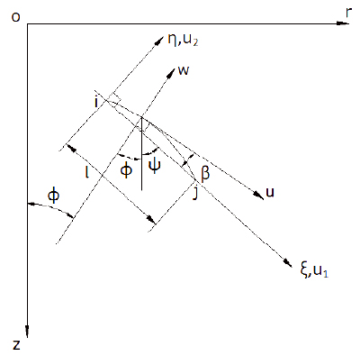
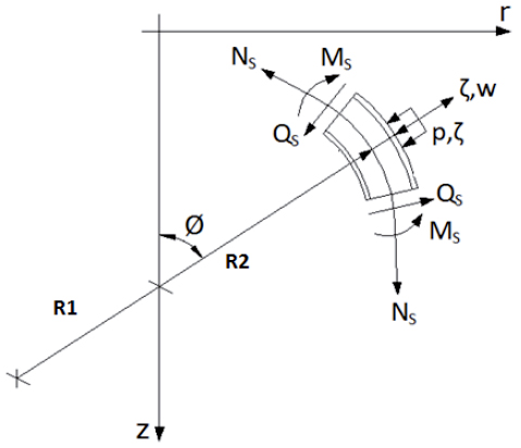
The geometry of an axisymmetric shell is uniquely defined through the shell meridian. The three layer sandwich shell is treated as an equivalent single layer with perfect bonding at layer interfaces for effective load transfer from facing to core. The doubly curved geometry of the element has been represented by a substitute curve of fifth order polynomial in terms of normalized coordinate (ξ) and matches the position, slope and curvature of the shell meridian at nodal circles. The orientation of the meridional curve in local rectilinear coordinate system (ξ,η) and the position of nodes and the dof associated with each node has been indicated in the Figure 1 (a) and (b). The local coordinate system (ξ,η) is placed at the middle surface of the shell. The element has two end nodes and three internal nodes. Figure 2 illustrates the moment and stress resultants, where ζ is the distance normal to the middle surface in the direction of w. The individual layer thickness is measured with reference to middle plane of shell. The geometry of the substitute curve has been represented as:

The values of the coefficients α1 = α4 have been arrived based on the geometry of the curve to ensure compatibility of slope and curvature.
For an axisymmetric shell the global displacement of a point is uniquely determined by two components u and w respectively. The meridional displacement of each layer has been assumed to vary linearly along the thickness with constant radial displacement through the thickness of the shell. The displacements and strains are independent of the circumferential variable ϑ for axisymmetric problems. The meridional displacements of the core and the facings are expressed in terms of the middle plane displacements (u, w), the rotation of the tangent to the meridian (χ) and shearing strain of the facing and core (γc, γf ) as:

In a sandwich shell the bending rotation of the tangent to the meridian χb has contributions from shear deformation of facing(γf) and core (γc ) and has been expressed as:

The shell kinematics is described in local coordinate system (ξ, η). The translations u 1 and u 2 have been represented by cubic variation of the normalized local rectilinear coordinate ξ whereas shear strains of the core and facings have been assumed to vary quadratically. Hence the kinematic field for the axisymmetric sandwich shell element at any point is described in terms of the polynomial functions in local coordinates as:

The shear warping angle has been defined as:

The meridional and radial displacements of the shell midsurface (u, w) can be expressed in local coordinate as:

Transforming the meridional rotation χ defined in (equation 3) in local coordinates as:

The matrix {q'} consisting of the dof can be related to the nodal displacements  using interpolation functions as:

where:


[φ(ξ)] defines the coefficients of the assumed displacement field in terms of ξ. The matrix [A] relates the nodal displacements to generalized constants {a}.
2.2 Strain-Displacement Relations
The strain displacement equations are made available from Novozhilov's shell theory which incorporates the effects of transverse shear deformations. The total shell strain {eβk } for layer k (core and facing) accounting the middle plane strains{ε0 βk } along with the change in curvatures {κβk } of the axisymmetric sandwich shell can be expressed as:


The total strain vector{e(ξ)} consisting of strains in meridional and hoop directions and shear strains of the core and facings together has been represented in matrix form as:


The geometry thickness matrix for the sandwich shell is:

The strains of the middle surface of the core in meridional, circumferential and transverse directions in terms of displacements have been stated as:

The strain components in the middle surface of the facings have been described as:


The linear components of curvature in core and facings have been defined as:

The strain vector ε(ξ) described in (Eq. 14) can be expressed in terms of global displacements using the (Eq. 18) to (20) and annotated in matrix form as:

The nodal parameters {q'} and global displacements {r'} can be related using nodal parameter displacement relational matrix defined in (Eq. 6):

Where

Substituting for {q'} derived in (Eq. 8) in the expression for global displacement vector, results in the following strain displacement relation:

2.3 Constitutive Relations
The relation between inplane stresses and strains for axisymmetric deformation has been represented by a state of generalized plane stress. Stress-strain relationships for all layers have been expressed in matrix form as:

The total stress vector includes stresses in meridional and hoop directions and transverse shear stress for both core and facing:

The constitutive matrix for the sandwich shell incorporates the contribution from the two facings in addition to the core and has been expressed in matrix form as:

The constitutive matrix for each isotropic axisymmetric layer k (core and facings) with principal axes in the meridional and circumferential directions has been defined as:

For composite or sandwich shell, each lamina is considered as orthotropic. A coordinate transformation of the stresses is required between the lamina and the laminate coordinate systems.
2.4 Element Stiffness Matrix
The linear elastic stiffness matrix of the axisymmetric shell element in local coordinates has been derived by minimizing the total potential of the structure:

The modified rigidity matrix has been described as:

2.5 Element Load Vector
The distributed load has been transformed to equivalent nodal circle load and added up at nodes to establish the nodal load vector. The consistent load vector for the element has been obtained in terms of interpolating polynomials and the surface loads and has been illustrated in (Eq. 31):

2.6 Transformation, Assembly and Solution
The stiffness matrix [kα ] and load matrix [Qα ] in local coordinate (ξ-η) are transformed into global coordinates for assembly. The axisymmetric elements are assumed to connect at the nodal circles. The process of the assemblage of element stiffness matrix and force matrix is carried out. The nodal displacements have been evaluated using any the Gauss elimination procedure. The stresses are obtained through the post processing and include the meridional, hoop and transverse shear stress for the top and bottom facing and the core and made available as:

The extensional stresses, membrane stress resultants, bending moment resultants in principal directions and the transverse shear stress resultant for the facings as well as core can be evaluated using the element.
3 NUMERICAL INVESTIGATIONS
The above finite element formulation for doubly curved shell has been implemented in MATLAB. Validation of the element has been done and the applicability of the element for the analysis of various shell forms has been illustrated.
3.1 Hemispherical Shell Under Membrane Load
A hemispherical shell under membrane load investigated by (Abel and Popov, 1968Abel, J.F. and Popov, E.P. (1968). Static and dynamic finite element analysis of sandwich structures. In: Proc. Conf. Matrix Meth. Struct, AFDL TR-68-150, 213-245.) has been considered for validating the newly developed axisymmetric element. A 100" radius spherical dome as shown in the Figure 3, has been subjected to a uniform external pressure of 1 psi with roller supports at the ends. The hemispherical shell has been discretized into 3 elements. The radial and meridional displacements and stress resultants obtained from the present element have been compared with the solution made available by (Abel and Popov, 1968Abel, J.F. and Popov, E.P. (1968). Static and dynamic finite element analysis of sandwich structures. In: Proc. Conf. Matrix Meth. Struct, AFDL TR-68-150, 213-245.) and the finite element results from Equivalent Single Layer Model (ESLM) in ANSYS using SHELL 281 elements and shown in Table 1 for angular position φ=600. The properties of the core and facing are: Ec=2.6x10⁴psi, Ef =104 psi, νc= νf = 0.3, and the thickness of core and facing are: hc =0.5 in, hf = 0.04 in.
Comparison of structural response between element formulation, ESLM and classical solutions.
In the ESLM, the hemisphere has been discretized using 509 number of SHELL 281 elements with 1646 number of nodes with symmetry condition imposed along the meridional edges.
The maximum percentage variation in radial displacement with reference to theoretical solution is observed near the roller support for the element and is merely 0.037%. The meridional displacement along with meridional and hoop stress resultants evaluated from the element are in excellent agreement with classical solutions and illustrates the improvement in results achieved by matching the curvatures at nodal circles. A near to zero value has been obtained for the meridional and hoop moments and transverse shear stress resultants for the present element. The three element representation precisely idealised the shell geometry with no spurious bending moments and shear forces at nodes. The above validation demonstrates the accuracy and convergence of stress resultants and displacements achieved with the present element formulation.
3.2 Shallow Spherical Cap with Partial Distributed Loading
A simply supported shallow spherical cap of 20 in radius analysed by (Rossettos, 1967Rossettos, J.N. (1967). Deflection of shallow spherical sandwich shells under local loading, NASA TND 3855.) as shown in Figure 4 has been considered. Rossettos has derived the closed form solution by considering a soft core for the sandwich shell. The material properties and thickness of the core and facing has been chosen as follows: Ec=0 psi, Gc=105 psi, νc= 0, Ef =107 psi, Gf =1020psi, νf = 0.3, hc=0.95in, hf =0.025in.
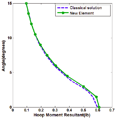
The deviation with respect to classical solution does not exceed 4.04 % for transverse deflection and 2.17% for membrane hoop force with 10 element representation. The element predicts the hoop moment with good accuracy. The variation of the radial deflection and hoop moment along the shell meridian has been shown in Figures 5 and 6 respectively.
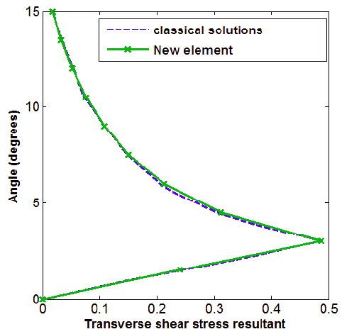
The transverse shear stress resultant obtained from the axisymmetric element has been compared with the classical solution and shown in Figure 7. The accuracy of the element in computing the transverse shear stress resultant with unit shear correction factor has been indicated in Figure 7. The quadratic shear model incorporated in the doubly curved sandwich element reasonably captures the rapid variation of shear of a sandwich shell with soft core. This shows the relevance of the present formulation for the analysis of subsea shells with PVC core.
Variation of transverse shear stress resultant (lb) for spherical shell along the meridian.
4 CONCLUSIONS
A new slope and curvature compatible doubly curved equivalent single layer finite element has been developed for linear elastic analysis of axisymmetric sandwich shells. The element is capable of effectively modelling the shell meridian while accounting for the material property variation in the facing and core. The element is competent in precise representation of transverse shear and prediction of interlaminar stresses. Unlike the conventional formulation where bending of facing and shear of core are taken into account, the present element takes into consideration the bending of core and shearing of facing as well, which are essential parameters for the true representation of structural behaviour of soft core sandwich shells which is applicable to subsea conditions. This first order Shear Deformation element effectively predicts the structural response using physically meaningful dofs at low computational cost compared to elements based on higher order shear deformation theory which utilises higher order dofs. Since the element has all these significant characteristics by genere, a mesh with fewer numbers of new elements has been capable of exhibiting good performance, allowing drastic reduction in computation time for analysis of sandwich shells. The element can be efficiently used for predicting the response of axisymmetric sandwich shells and multilayer composite thin and thick shells with reasonable accuracy.
References
- Abel, J.F. and Popov, E.P. (1968). Static and dynamic finite element analysis of sandwich structures. In: Proc. Conf. Matrix Meth. Struct, AFDL TR-68-150, 213-245.
- Brink, N. (1964). Sandwich cylinder construction for underwater pressure vessels, Nav Eng J, 76: 951-954.
- Dau, F., Polit, O. and Touratier, M. (2004). An efficient c1 finite element with continuity requirements for multilayered/sandwich shell structures, Comput Struct, 82: 23-26: 1889-1899.
- Goode, C.D. and Fatheldin, Y.T. (1980). Sandwich cylinders (steel-concrete- steel) subjected to external pressure, ACI J, 77: 109-115.
- Kant, T. and Kommineni, J.R. (1994). Geometrically non-linear transient analysis of laminated composite and sandwich shells with a refined theory and co finite elements, Comput Struct, 52: 6: 1243-1259.
- Kant, T. and Menon, M.P. (1989). Higher order theories for composite and sandwich cylindrical shells with co finite element, Comput Struct, 33: 5: 1191-1204.
- Lee, G.C., Kweon, J.H. and Choi, J.H. (2013). Optimization of composite sandwich cylinders for underwater vehicle application, Compos Struct, 96: 691-697.
- Liang, C.C, Chen, H.W. and Jen, C.Y. (2003). Optimum design of filament-wound multilayer-sandwich submersible pressure hulls, Ocean Eng, 30: 15: 1941-1967.
- Monforton, G.R. and Schmit, L.A. (1969). Finite element analysis of sandwich plates and cylindrical shells with laminated faces. In: Proc. Conf. Matrix Meth. Struct, AFFDL-TR-68-155, 573-608.
- Narewski M. and Rowiñski L.A, (1974). Underwater technology developments in ship research institute of technical university of Gdansk.
- Noor, A.K., Burton, W.S. and Charles, W.B. (1996). Computational models for sandwich panels and shells, Appl. Mech. Rev, 49: Number 3.
- Polit O. and Touratier M.A. (2002). Multilayered / sandwich triangular finite element applied to linear and non-linear analyses, Compos Struct, 58: 1:121-128.
- Polit, O. and Touratier, M. (2000). High order triangular sandwich plate finite element for linear and nonlinear analyses, Comput Methods Appl Mech Eng, 185: 305-324.
- Qatu, M.S, Asadi, E. and Wang, W. (2012). Review of recent literature on static analysis of composite shells: 2000-2010. Open J Compos Materials, 2: 61-86.
- Rahmani, O., Khalili, S.M.R. and Thomsen, O.T. (2012). A high-order theory for the analysis of circular cylindrical composite sandwich shells with transversely compliant core subjected to external loads, Compos Struct, 94, 7: 2129-2142.
- Reddy, J.N. (1990). A general nonlinear third-order theory of plates with moderate thickness, Int J Non-Lin Mech, 25: 677-86.
- Reddy, J.N. and Liu, C.F. (1990). A higher order shear deformation theory of laminated elastic shells, Int. J. Eng. Sci, 23: 319-330.
- Rossettos, J.N. (1967). Deflection of shallow spherical sandwich shells under local loading, NASA TND 3855.
- Smith, C.S. (1991). Design of submersible pressure hulls in composite materials, Mar Struct, 4: 141-182.
- Smith, J.R., Graham, D. and Creswell, D.J. (1999). A foam sandwich submarine hull, DERA novel hull model No. 1, In: Proceedings of Warship '99: The International Symposium on Novel Structures, pp. 14-16.
- Soldatos, K.P. and Shu, X. (1999). On the stress analysis of cross-ply laminated plates and shallow shell panels. Compos Struct 46: 333-344.
- Xue, M.D., Chen, L.J. and Hu, N. (2003). The stress analysis of sandwich shells faced with composite sheets based on 3d fem, Compos Struct, 60: 33 - 41.
- Yaqoob, Y.M. and Kapuria, S. (2013). An efficient layerwise finite element for shallow composite and sandwich shells, Compos Struct, 98: 202-214.
Publication Dates
-
Publication in this collection
July 2016
History
-
Received
28 Aug 2015 -
Reviewed
18 Jan 2016 -
Accepted
08 Mar 2016