Abstract
This paper is concerned with the dynamic behavior of the spinning Functionally Graded Material (FGM) shaft on rigid bearings. A p- version, hierarchical finite element is employed to define the model. A theoretical study allows the establishment of the kinetic energy and the strain energy of the shaft, necessary to the result of the equations of motion. In this model the transverse shear deformation, rotary inertia and gyroscopic effects have been incorporated. A hierarchical beam finite element with six degrees of freedom per node is developed and used to model the shaft. A program is elaborate for the calculation of the natural frequencies of a spinning FGM shaft. To verify the present model, the results are compared with those available in the literature. The efficiency and accuracy of the methods employed are discussed.
Spinning shaft; Functionally Graded Material; FGM; p- version; hierarchical finite element method; FEM
Dynamic analysis of a spinning functionally graded material shaft by the p- version of the finite element method
Abdelkrim Boukhalfa
Department of Mechanical Engineering, Faculty of Technology, University of Tlemcen, Algeria E-mail: BKA1975E@yahoo.fr
ABSTRACT
This paper is concerned with the dynamic behavior of the spinning Functionally Graded Material (FGM) shaft on rigid bearings. A p- version, hierarchical finite element is employed to define the model. A theoretical study allows the establishment of the kinetic energy and the strain energy of the shaft, necessary to the result of the equations of motion. In this model the transverse shear deformation, rotary inertia and gyroscopic effects have been incorporated. A hierarchical beam finite element with six degrees of freedom per node is developed and used to model the shaft. A program is elaborate for the calculation of the natural frequencies of a spinning FGM shaft. To verify the present model, the results are compared with those available in the literature. The efficiency and accuracy of the methods employed are discussed.
Keywords: Spinning shaft, Functionally Graded Material, FGM, p- version, hierarchical finite element method, FEM.
INTRODUCTION
The structural systems spinning about their longitudinal axis are used in the most diverse areas of modern technology. In this sense, these are used as a shaft, for power transmission in aeropropulsion systems, in helicopter drive applications, and in industrial machines such as steam and gas turbines. In addition, these are used in the cutting tools used in boring and milling operations. Moreover, the axial booms attached to spin-stabilized spacecraft and subjected to solar heating.
In order to enhance their vibration behavior, eliminate or even postpone the occurrence of any instability jeopardizing their operational life and expand their efficiency, a better understanding of their behavior is required. In addition, having in view that these structural systems operate in severe environmental conditions such as high temperatures, in order to resist without catastrophic failures, advanced structural models have to be devised.
In this context, the application of the functionally gradient material (FGM) concept is likely to eliminate the shortcomings that are inherently generated when instead; standard composite material structures are used.
The FGM is a new kind of composite material developed recently in which the material property graded distribution is formed by the composition of different material media in variant proportion in space, so as to meet the requirements of material properties for different parts of a member. In the meanwhile, as each part of the material of structure varies in continuous way, there is more advantage of the material properties than ordinary laminated and composed ones. Such kind of composite material composed non-uniformly and continuously in structure by different materials in desired way makes development of material stride forward towards a higher level (Koizumi, 1993).
FGMs have been widely used in various fields including electronics, chemistry, optics, biomedicine, etc. The concept of fabricating FGMs was first introduced as a means of preparing thermal barrier materials by a group of material scientists (Makino et al., 1994) in Japan in 1984. FGMs are made by combining different materials with powder metallurgy methods.
In FGMs, the material distribution is governed by the volume fraction law and varied radially in a functionally graded shaft for a constituent material. This leads to continuous change in the composition of the shaft and results in gradients in the mechanical and thermal properties.
The literature on the vibration analysis of FGM rotating shaft is limited to few published articles. Many of these studies are for isotropic and composite shells; you can see these articles in reference (Hosseini-Hashemi et al., 2013).
The works of Oh et al. (2003-2005) and Fazelzadeh et al. (2007a-2007b) are among the few papers devoted to the mechanics of thin-walled beams constructed with functionally graded materials. The scope of these papers has been mainly directed towards the analysis of rotating beams and secondarily to the analysis of thermo-elastic coupling effects associated with graded properties. Oh et al. (2003-2005) also focused their attention to the study of dynamic stability of cylindrical spinning beams. The studies on vibration of rotating beam made of FGMs using the p-version of FEM have not been seen in the literature.
This paper deals with the p-version, hierarchical finite element method applied to free vibration analysis of spinning FGM shafts. The hierarchical concept for finite element shape functions has been investigated during the past 25 years. Babuska et al. (1981) established a theoretical basis for p-elements, where the mesh keeps unchanged and the polynomial degree of the shape functions is increased; however, in the standard h-version of the finite element method the mesh is refined to achieve convergence and the polynomial degree of the shape functions remains unchanged. Since then, standard forms of the hierarchical shape functions have been represented in the literature elsewhere; see for instance (Szabo and Sahrmann, 1988; Szabỏ and Babuška, 1991).
Meirovitch and Baruh (1983) and Zhu (1986) have shown that the hierarchical finite element method yields a better accuracy than the h-version for eigenvalues problems. The hierarchical shape functions used by Bardell (1989) are based on integrated Legendre orthogonal polynomials; the symbolic computing is used to calculate the mass and stiffness matrices of beams and plates. Coté and Charron (2001) give the selection of p-version shape functions for plate vibration analysis.
In the presented FGM shaft model, the Timoshenko theory will be adopted. It is the purpose of the present work to study dynamic characteristics such as natural frequencies, whirling frequencies, and the critical speeds of the spinning FGM shaft. In the model, the transverse shear deformation, rotary inertia, and gyroscopic effects have been incorporated. To determine the rotating shaft system's responses, the hierarchical finite element method with trigonometric shape functions (Boukhalfa et al., 2008-2010) is employed to solve the equations of motion.
2 EQUATIONS OF MOTION
2.1 Kinetic and strain energy expressions of the shaft
The shaft is modeled as a Timoshenko beam, that is, first-order shear deformation theory with rotary inertia and gyroscopic effect is used. The shaft rotates at constant speed about its longitudinal axis. The shaft has a uniform, circular cross section.
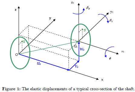
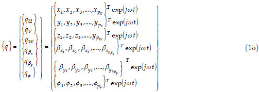
The following displacement field of a spinning shaft is assumed by choosing the coordinate axis x to coincide with the shaft axis:
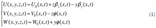
Where U, V and W are the displacements due to bending of any point on the cross-section of the shaft in the x, y and z directions respectively, the variables U0, V0 and W0 are the displacements due to bending of the shaft's axis (longitudinal displacement, horizontal transverse displacement and vertical transverse displacement), while βX and βy are the rotation angles of the cross-section, about the y and z axis respectively. The ϕ is the angular displacement of the cross-section due to the torsion deformation of the shaft (see figure 1).
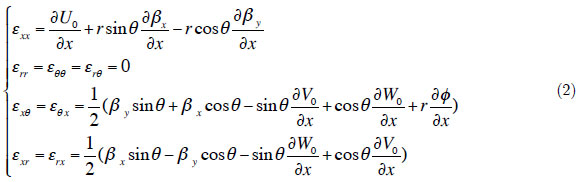
The strain components in the cylindrical coordinate system (As shown in figure 2-3) can be written in terms of the displacement variables defined earlier as
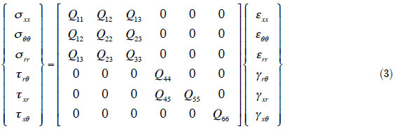
Where Qij (i,j = 1,6) are the effective elastic constants.
The stress-strain relations in the cylindrical coordinate system (see figure 4) can be expressed as
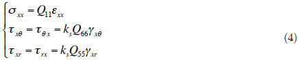
where Q11 = , Q55 = Q66 =
  and ks is the transverse shear correction factor.
2.2 Gradation relation
There are some models for expressing the variation of material properties in FGMs in the literature. The most commonly used of these models is the power-law distribution of the volume fraction.
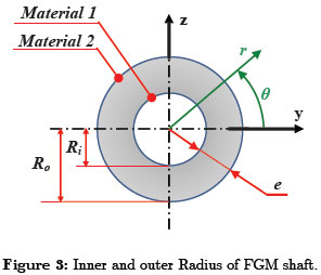
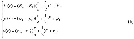
Based on this model, the material property gradation through the shaft radius is represented in terms of the volume fraction by Reddy and Chin (1998)

where P(r) denotes a generic material property and Po and Pi denote the property of the outer and inner faces of the shaft, respectively (e.g. elastic modulus) and n is a grading index that dictates the material variation profile through the thickness(radius). This study assumes that the elastic modulus E, density ρ and the Poisson's ratio ν vary according to the gradation relation (5)
The formula of the strain energy is

The various components of strain energy of the shaft are presented as follow
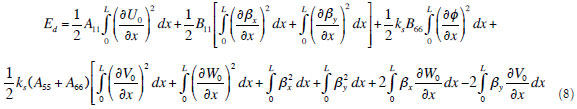
where

The kinetic energy of the spinning FGM shaft, including the effects of translatory and rotary inertia (see Chang M.Y. et al. (2004)), can be written as

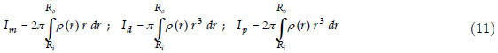
where Ω is the rotating speed of the shaft which is assumed constant, L is the length of the shaft, the 2ΩIp βx βy term accounts for the gyroscopic effect, and Id (βX2 + βY2) represent the rotary inertia effect.. The mass moments of inertia Im, the diametrical mass moments of inertia Id and polar mass moment of inertia Ip of spinning shaft per unit length are defined in equation (11). As the Ω2 ID (βX2 + βY2) term is far smaller than Ω2 IP , it will be neglected in further analysis.
2.3 Hierarchical Beam element formulation
The spinning flexible shaft is descretised by hierarchical beam element (p- element) with two nodes 1 and 2 is shown in figure 5. The element's nodal d.o.f. at each node are U0 , V0 , W0 ,βx , βy and ϕ.
The local and non-dimensional co-ordinates are related by

The vector displacement formed by the variables U0 , V0 , W0 ,βx , βy and ϕ can be written as
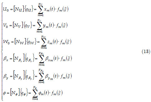
where [N] is the matrix of the shape functions, given by

where pU , pV , pW , pβx , pβy and pΦ are the numbers of hierarchical terms of displacements (are the numbers of shape functions of displacements). In this work, pU = pV = pW = pβx = pβy = pΦ = p
The vector of generalized coordinates given by
The group of the shape functions used in this study (see Houmat A. (2001)) is given by
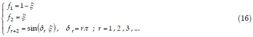
The functions (f1, f2) are those of the finite element method necessary to describe the nodal displacements of the element; whereas the trigonometric functions fr+2 contribute only to the internal field of displacement and do not affect nodal displacements. The most attractive particularity of the trigonometric functions is that they offer great numerical stability. The shaft is modeled by one element called hierarchical finite elements with p shape functions.
After modelling the spinning FGM shaft using the p- version of the finite element method and applying the Euler-Lagrange equations, the motion's equations of free vibration of spinning flexible shaft can be obtained.

[M] and [K] are the mass and stiffness matrix respectively, [G] is the gyroscopic matrix (the different matrices of the equation (17) are given in the appendix).
3 RESULTS
A program based on the formulation proposed to resolve the resolution of the equation (17).
To investigate the vibration characteristics of FGM shaft, the functionally gradient material considered is to be composed of two material constituents. The material properties are graded in the thickness (radial) direction according to a volume fraction power law distribution. The functionally graded materials are stainless steel and nickel, and Zirconia. Their material properties determined at T=300 K, are given in Table 1. Four types of FGM shaft are considered to be made from these materials.
3.1 Convergence
First, the mechanical properties of Type I FG shaft are listed in table 1. The geometric parameters are e/D =0.002, L/D =20. The shear correction factor ks =0.5 and the rotating speed Ω =0. In this example, the FG M spinning shaft is modeled by one element of length L.
The results of the three bending modes for various boundary conditions and power law index n of the FGM shaft as a function of the number of hierarchical terms p are shown in figure 6. Figure clearly shows that rapid convergence from above to the exact values occurs when the number of hierarchical terms increased. This shows the exactitude of the method even with one element and a reduced number of the shape functions. It is noticeable in the case of low frequencies, a very small p is needed (p=5 sufficient), whereas in the case of the high frequencies, and in order to have a good convergence, p should be increased.
3.2 Validation
In the first example, the natural frequency ω for the 3 bending modes of a simply supported homogeneous shaft for different rotating speed Ω are compared with those available in the literature to verify the present model. The diameter D and the total length L of the solid shaft are 0.05 m and 0.9 m respectively. The elastic modulus E, density ρ and the Poisson's ratio ν are E =2·1011 N/m2, ν= 0.3, ρ= 7800 kg/m3. A shear correction factor of 6/7 is also used. The shaft is modeled by one element of length L. The shaft is simply-supported at the ends. In this validation, p =10.
The result obtained using the present model is shown in table 2 together with the analytical solutions (René-Jean (1988)) by using the Euler-Bernoulli beam theory. In our work, the shaft is modeled by one element with two nodes by using the Timoshenko beam theory. The rapid convergence while taking one element and a reduced number of shape functions shows the advantage of the method used.
In the second example, the natural frequencies of FGM shaft are analyzed and compared with those available in the literature to verify the present model. In this example, the Type II FGM hollow shaft is investigated. The properties of material are listed in table 1. The geometric parameters are e/D =0.002, L/D =20. The shear correction factor ks =0.5 and the rotating speed Ω =0. In this example, the FGM spinning shaft is modeled by one element of length L. The shaft is simplysupported at the ends. In this validation, p =10.
The result obtained using the present model is shown in table 3 together with those of referenced paper. In this reference, Loy et al. (1999) investigated the free vibration of simply supported FGM cylindrical shells. This is extended to cylindrical shells with deferent support conditions in the work of Pradhan et al. (2000). The governing equations derived based on the classical shell theory assumption are solved using Rayleigh-Ritz method. It can be seen from this table that the present results are in excellent agreement with those of the literature.
3.3 Results and interpretations
In this study, the results obtained for various applications are presented. The influence of the mechanical and geometrical parameters on the natural frequencies of the spinning FGM shafts is studied. In this study, p = 10.
3.3.1 Influence of the gyroscopic effect, the ratios L/D and e/D on the natural frequencies
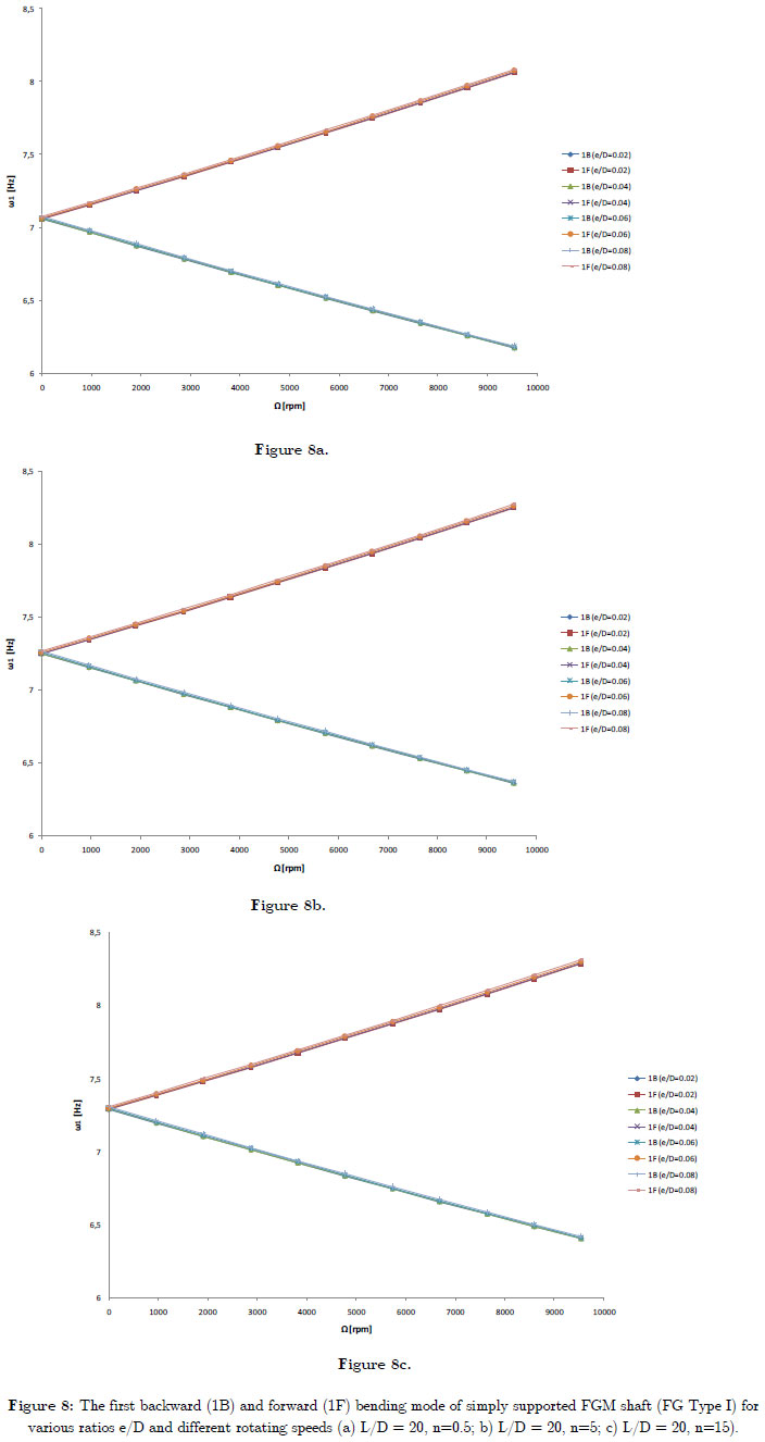
In the following example, the frequencies of a FGM spinning shaft are analyzed, FGM shaft has stainless steel (SS) on its inner surface and nickel (Ni) on its outer surface (FG Type I). The mechanical properties of shaft are shown in table 1, with ks = 0.503. Figure 7 shows the variation of the bending fundamental frequency ω as a function of rotating speed Ω of simply supported FGM shaft for various ratios L/D and different power law index n. Figure 8 shows the variation of the bending fundamental frequency ω as a function of rotating speed Ω of simply supported FGM shaft for various ratios e/D and different power law index n.
The gyroscopic effect inherent to rotating structures induces a precession motion. When the rotating speed increase, the forward modes (1F) increase, whereas the backward modes (1B) decrease. The gyroscopic effect causes a coupling of orthogonal displacements to the axis of rotation, and by consequence separate the frequencies in two branches: backward precession mode and forward precession mode. In all cases, the forward modes increase with increasing rotating speed however the backward modes decrease.
For the different power law index n, the natural frequency decreases as L/D ratio increases. Further, natural frequency of the FGM shaft increases as e/D ratio increases. It is noticed the influence of the e/D ratio on the natural frequency is almost negligible; the curves are almost identical for the various e/D ratios and n. This is due to the deformation of the cross section is negligible, and thus the natural frequency of the thin-walled shaft would approximately independent of thickness ratio e/D.
3.3.2 Influence of the FGM Type on the natural frequencies
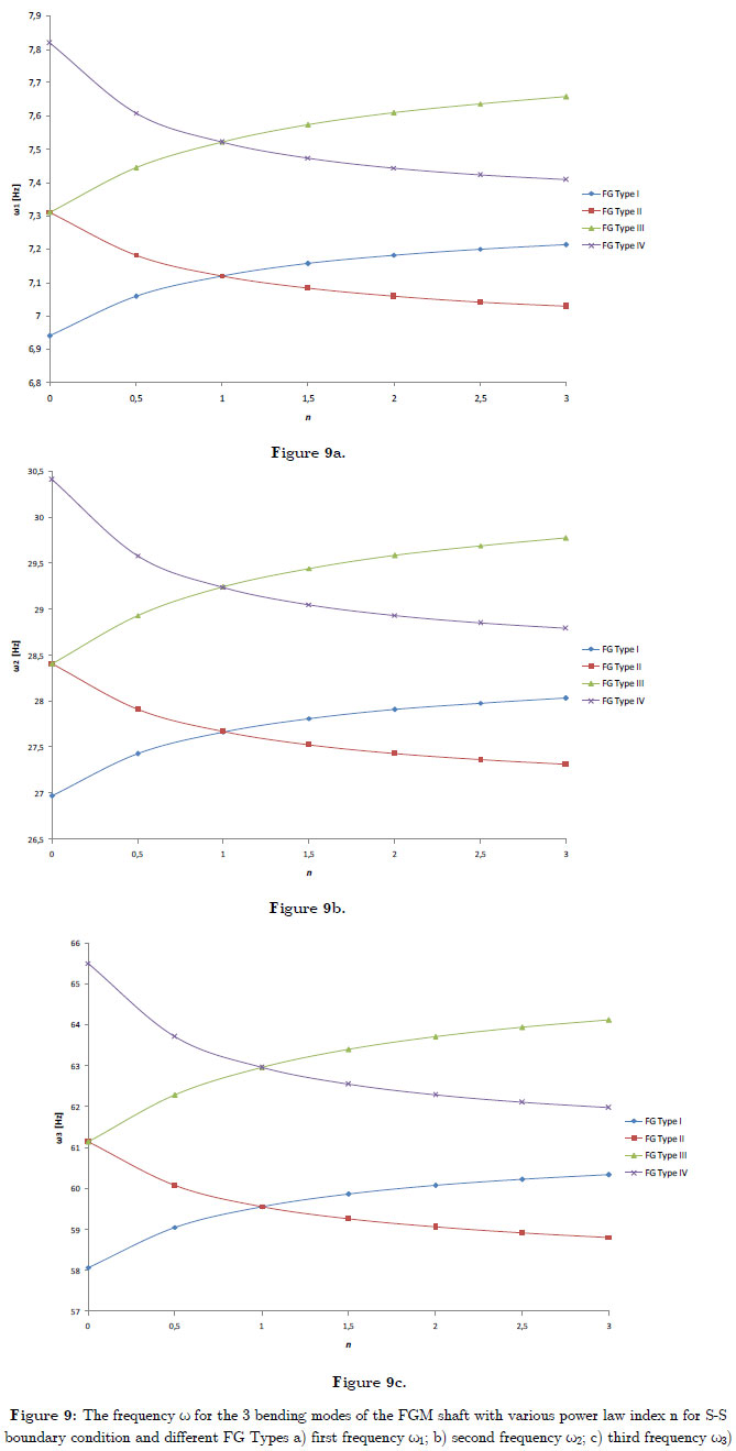
In this example presented on the vibration of a simply supported FGM shafts. The functionally gradient material (FGM) considered is composed of Stainless Steel, Nickel and Zirconia and its properties are graded in the thickness (radial) direction according to a volume fraction power-law distribution. In this study, the results for the frequency characteristics, the influence of the constituent volume fractions and the effects of the FGM configuration are presented. The influence of constituent volume fractions is studied by varying the volume fractions of the stainless steel, nickel and Zirconia. This is carried out by varying the value of the power-law index n. The effects of the FGM configuration are studied by studying the frequencies of four types of FGM shaft, are presented in the beginning of the results.
Figure 9 shows the 3 bending modes of the FGM shaft with various power law index n for S-S boundary condition and different FG Types. For the Type I FG (Type III FG) shafts, the natural frequencies increased when n increased, and for the Type II FG (Type IV FG) shafts, the natural frequencies increased when n decreased. In Types I and II FG shafts, the natural frequencies for all values of n lie between those for a Stainless Steel and Nickel shaft. In Types III and IV FG shafts, the natural frequencies for all values of n lie between those for a Stainless Steel and Zirconia. For n>1, the natural frequencies for Type I FG (Type III FG ) shafts are higher than for Type II FG (Type IV FG ) shafts and for n<1, the natural frequencies for Type II FG (Type IV FG) shafts are higher than Type I FG (Type III FG ) shafts. For the Type I FG (Type III FG) shafts, the behaviors of volume fraction of stainless steel (Zirconia) and volume fraction of Nickel (stainless steel) are opposite to that for the Type II FG (Type IV FG) shafts.Thus the constituent volume fractions and the configurations of the constituent materials affect the natural frequencies.
4 CONCLUSIONS
The analysis of the free vibrations of the spinning FGM shafts using the p-version of the finite element method with trigonometric shape functions is presented in this work. The results obtained agree with those available in the literature. Several examples were treated to determine the influence of the various geometrical and physical parameters of the spinning shafts. This work enabled us to arrive at the following conclusions:
- Monotonous and uniform convergence is checked by increasing the number of the shape functions p. The convergence of the solutions is ensured by the element beam with two nodes. The results agree with the solutions found in the literature.
- The gyroscopic effect causes a coupling of orthogonal displacements to the axis of rotation, and by consequence separates the frequencies in two branches, backward and forward precession modes. In all cases the forward modes increase with increasing rotating speed however the backward modes decrease. This effect has a significant influence on the behaviours of the spinning shafts.
- The dynamic characteristics and in particular the natural frequencies of the spinning FGM shafts are influenced appreciably by changing the power low index, the constituent materials, the length, the mean diameter, the rotating speed and the boundary conditions.
- The natural frequencies of the thin-walled spinning FGM shaft are approximately independent of the thickness ratio and mean diameter of the spinning shaft.
Prospects for future studies can be undertaken following this work: a study which takes into account damping interns in the case of a functionally graded material rotor with flexible disks, supported by supports with oil and subjected to disturbing forces like the air pockets or seisms, etc.
NOMENCLATURE
APPENDIX
The various matrices of equation (17) which assemble the elementary matrices of the system as follows
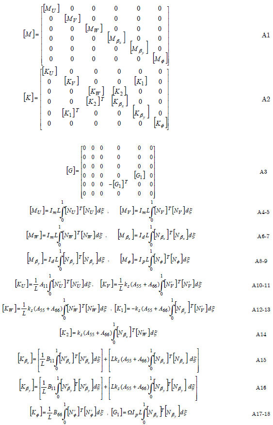
Where  , with (i = U, V, W, βx , βy ,ϕ)
The terms of the matrices are a function of the integrals:
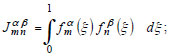
(m, n) indicate the number of the shape functions used, and ( α, β ) is the order of derivation.
- Babuška, I., Szabỏ, B.A., and Katz, I.N. (1981). The p-version of the finite element method. SIAM Journal on Numerical Analysis 18(3):515-545.
- Bardell, N.S. (1989). The application of symbolic computing to the hierarchical finite element method. International Journal for Numerical Methods in Engineering 28(5):1181-1204.
- Boukhalfa, A. and Hadjoui, A. (2010). Free vibration analysis of an embarked rotating composite shaft using the hp- version of the FEM. Latin American Journal of Solids and Structures, Vol. 7, No. 2: 105-141
- Boukhalfa, A.; Hadjoui, A. & Hamza Cherif, S.M. (2008). Free vibration analysis of a rotating composite shaft using the p-version of the finite element method. International Journal of Rotating Machinery. Article ID 752062. 10 pages, Vol. 2008
- Chang M. Y., et al. (2004). A Simple Spinning Laminated Composite Shaft Model, International Journal of Solids and Structures. 41:637-662.
- Coté, A., and Charron, F.(2001).On the selection of p-version shape functions for plate vibration problems. Computers & Structures 79(1):119-130.
- Fazelzadeh, S. A., Hosseini, M. (2007 b). Aerothermoelastic behavior of supersonic rotating thin-walled beams made of functionally graded materials. Journal of fluids and structures 23:1251-64.
- Fazelzadeh, S. A., Malekzadeh P., Zahedinejad P., Hosseini M. (2007a). Vibration analysis of functionally graded thin-walled rotating blades under high temperature supersonic flow using the differential quadrature method. Journal of Sound and Vibration 306:333-48.
- Hosseini-hashemi, S.H., Ilkhani, M.R., Fadaee, M. (2013). Accurate natural frequencies and critical speeds of a rotating functionally graded moderately thick cylindrical Shell. International Journal of Mechanical Sciences 76:9-20.
- Houmat, A. (2001). A sector fourier p-element applied to free vibration analysis of sectorial plates. Journal of Sound and Vibration. 243(2):269-282.
- Koizumi, M. (1993). The concept of FGM, ceramic Transactions, Functionally Gradient Materials 34: 3-10.
- Loy, C.T., Lam, K.Y., Reddy, J.N. (1999). Vibration of functionally graded cylindrical shells. Int J Mech Sci 41:309-24.
- Makino, A., Araki, N., Kitajima, H., and Ohashi, K. (1994). Transient temperature response of functionally gradient material subjected to partial step-wise heating. Trans. Jpn Soc. Mech. Eng. B 60: 4200-4206 .
- Meirovitch, L., and Baruh, H. (1983). On the inclusion principle for the hierarchical finite element method. International Journal for Numerical Methods in Engineering 19(2):281-291.
- Oh, S.Y., Librescu L., Song, O. (2005). Vibration and instability of functionally graded circular cylindrical spinning thin-walled beams. Journal of Sound and Vibration 285(4-5):1071-91.
- Oh, S.Y., Librescu, L., Song, O. (2003). Thermoelastic modeling and vibrations of functionally graded thin-walled rotating blades. AIAA Journal 41(10):2051-60.
- Pradhan, S.C., Loy, C.T., Lam, K.Y., Reddy, J.N.(2000). Vibration characteristics of functionally graded cylindrical shells under various boundary conditions. Appl Acoust 61:111-29.
- Reddy, J.N., Chin C.D. (1998). Thermomechanical analysis of functionally graded cylinders and plates. J Therm Stresses 21(6):593-626.
- René-Jean G. (1988). vibrations des structures, Nş69 de la collection R&D d'EDF chez EYROLLES, p. 235-237.
- Szabỏ, B.A., and Babuška, I. (1991). Finite Element Analysis. JohnWiley & Sons, New York, NY, USA.
- Szabỏ, B.A., and Sahrmann, G.J. (1988).Hierarchic plate and shell models based on p-extension. International Journal for Numerical Methods in Engineering 26(8):1855-1881.
- Zhu, D.C. (1986). Development of hierarchical finite element method at BIAA. in Proceedings of the International Conference on Computational Mechanics volume I,123-128, Tokyo, Japan,
Publication Dates
-
Publication in this collection
08 Dec 2014 -
Date of issue
2014