Abstract
There are many methods for designing pile caps, but there is still no consensus on which one provides the best approach for the practical engineers. In Brazil, many structural designers use the classical Blévot method; however, the applicability of the method has been questioned after the revision of the NBR 6118 standard for design of concrete structures in 2014. To support structural designers, a strut-and-tie model has recently been developed that relates the classical method to the most current concepts of strut-and-tie models. The theoretical bearing capacity of four-pile cap obtained through several strut-and-tie models are compared with experimental tests. The results show that this recently developed model is suitable for the design of deep pile cap.
Keywords:
pile caps; strut-and-tie models; design; reinforced concrete
Resumo
Existem muitos métodos de dimensionamento de blocos de fundações, mas ainda não há consenso sobre qual método fornece a melhor abordagem para o engenheiro de projetos. No Brasil, muitos projetistas de estruturas utilizam o método clássico de Blévot, no entanto, com a revisão da norma NBR 6118 de projeto de estruturas de concreto em 2014, o meio técnico tem sido confrontado com dúvidas quanto a aplicabilidade desse método pela regulamentação vigente. De forma a contribuir com o tema, recentemente foi desenvolvido um modelo de bielas e tirantes que relaciona o método clássico com os conceitos mais atuais de modelos de bielas e tirantes. As resistências teóricas de blocos sobre 4 estacas obtidas através de vários modelos de bielas e tirantes são comparadas com ensaios experimentais. Os resultados obtidos mostram que o modelo recentemente desenvolvido é adequado para o dimensionamento de blocos rígidos.
Palavras-chave:
blocos de fundação; modelos de bielas e tirantes; dimensionamento; concreto armado
1. Introduction
Pile caps are tridimensional structural elements whose function is to transfer the forces in the column to a set of piles. These elements generally have low flexural reinforcement ratio and with no shear reinforcement within them. The lack of stirrups makes the structural behavior of the pile caps complex and highly dependent on the tensile strength of the concrete and on the confinement of plain concrete.
Currently, national and international standards or codes (e.g. [4[4] ASSOCIAÇÃO BRASILEIRA DE NORMAS TÉCNICAS (2014). NBR6118 - Projeto de estruturas de concreto - Procedimento. Rio de Janeiro.] and [19[19] ACI COMMITTEE 318 (2014). Building Code Requirements for Structural Concrete: (ACI 318-14) and Commentary. Farmington Hills, MI: American Concrete Institute.]) permit two different provisions for designing pile caps: one based on sectional analysis and the other on strut-and-tie models (STM). The first is the same sectional approach used for two-way slabs, while the second is based on the complete flow of forces within the pile caps using strut-and-tie models.
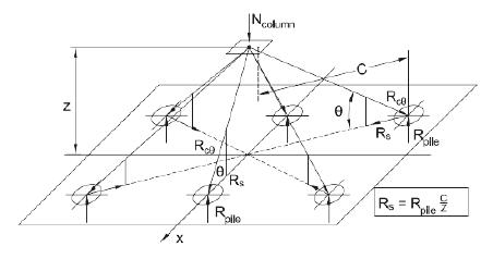
The approach by strut-and-tie models is generally recognized as the most appropriate for pile-caps design. Figure 1 shows a strut-and-tie model for four-pile caps.
The revision of NBR 6118 [4[4] ASSOCIAÇÃO BRASILEIRA DE NORMAS TÉCNICAS (2014). NBR6118 - Projeto de estruturas de concreto - Procedimento. Rio de Janeiro.] in 2014 added specific rules for the design of concrete structures by strut-and-tie models. However, the design strength of concrete struts and the design values of the compressive stress within nodes by this standard (established for the design of plane elements) are lower than those prescribed in the most widely used method in Brazil, known as Blévot or classical method (Blévot and Frémy [1[1] BLEVOT, J.; FRÉMY, R. (1967). Semelles sur pieux. Analles de l’Institut Technique du Batiment et des Travaux Publics., Paris, v.20, n.230.]), raising some doubts and difficulties in the technical community because of the conservatism in using such method with the resistance limits of NBR 6118 [4[4] ASSOCIAÇÃO BRASILEIRA DE NORMAS TÉCNICAS (2014). NBR6118 - Projeto de estruturas de concreto - Procedimento. Rio de Janeiro.].
For the reason mentioned above, it increased the interest of structural engineers in the Fusco Method [5[5] FUSCO, P. B. (1995). Técnicas de armar as estruturas de concreto. Editora PINI, São Paulo.], which maintains, with small changes, the well-established practice by the classical method. Although the Fusco Method [5[5] FUSCO, P. B. (1995). Técnicas de armar as estruturas de concreto. Editora PINI, São Paulo.] can be considered a consistent adaptation of the Blévot method and allows using the prescriptions of NBR 6118 [4[4] ASSOCIAÇÃO BRASILEIRA DE NORMAS TÉCNICAS (2014). NBR6118 - Projeto de estruturas de concreto - Procedimento. Rio de Janeiro.] without exaggerating in conservatism, it does not follow the modern concepts of strut-and-tie models (Schlaich et al. [20[20] SCHLAICH, J.; SCHÄFER, K.; JENNEWEIN, M. (1987). Toward a consistent design of structural concrete. PCI Journal, v.32, n.3; p.75-150.] and stress fields (Muttoni et al. [21[21] MUTTONI, A.; SCHWARTZ, J.; THÜRLIMANN B. (1997). Design of concrete structures with stress fields. Birkhäuser, 143p.]).
In order to align the normative prescriptions with the design methods of pile caps, a new method was developed and presented by Santos et al. [3[3] Santos, D. M.; Marquesi, M. L.; Stucchi, F. R. (2015). Dimensionamento de blocos de fundações sobre 2 e 4 estacas. In: ABNT NBR 6118:2014 comentários e exemplos de aplicação. IBRACON, 455-478, São Paulo.]. This method is based on a strut-and-tie model that mixes the classical and the Fusco methods in a consistent way following the modern concepts of strut-and-tie models and stress fields.
In this paper, some design methods of pile caps by strut and tie models are reviewed. The newly developed model by Santos et al., [3[3] Santos, D. M.; Marquesi, M. L.; Stucchi, F. R. (2015). Dimensionamento de blocos de fundações sobre 2 e 4 estacas. In: ABNT NBR 6118:2014 comentários e exemplos de aplicação. IBRACON, 455-478, São Paulo.] is discussed and results from tests are reviewed and compared with predictions from the different design methods. This comparative study also indicates the suitability of the recently developed model, and possible improvements are outlined.
2. Experimental data
There are several experimental test data on the bearing capacity of pile caps in the technical literature. A brief summary of these test results is presented.
The tests most known in Brazil were carried out by Blévot and Frémy [1[1] BLEVOT, J.; FRÉMY, R. (1967). Semelles sur pieux. Analles de l’Institut Technique du Batiment et des Travaux Publics., Paris, v.20, n.230.] who tested 116 pile caps with various features. There were 59 four-pile caps, 45 three-pile caps and 12 two-pile caps. Additionally, 94 tests at reduced-scale and 22 tests at full-scale. From the tests results and the strut-and-tie model proposed by M. Lebelle for designing footings, these researchers proposed a simplified strut-and-tie model for designing pile caps. This model is well established in Brazil and widely used by structural design offices.
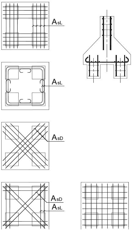
Figure 2 shows the different reinforcement arrangements used in four-pile caps tests. Blévot and Frémy [1[1] BLEVOT, J.; FRÉMY, R. (1967). Semelles sur pieux. Analles de l’Institut Technique du Batiment et des Travaux Publics., Paris, v.20, n.230.] noted that the four-pile caps with grid reinforcement arrangement had less bearing capacity than a similar pile cap with bunched square layout (in the case of four-pile caps, they observed 20% less bearing capacity). This finding, reproduced by other researchers (Clarke [9[9] CLARKE, J. L. (1973). Behavior and design of pile caps with four piles. Cement and concrete association, London, 19p. (Technical Report, n. 42.489).], Suzuki et al. [10[10] SUZUKI, K.; OTSUKI, K.; TSUBATA, T. (1998). Influence of bar arrangement on ultimate strength of four pile caps. Transactions of the Japan Concrete Institute, V. 20, pp. 195-202.]), shows the effectiveness of the strut-and-tie models over the sectional method (CEB-FIP Bulletin 73 [2[2] COMITÉ EURO-ITERNATIONAL DU BÉTON (1970). CEB-FIP Recommandations particulières au calcul et à l’execution des semelles de fondation. Bulletin d’Information, Paris, n.73.]), because the STM indicates that the tension forces are concentrated over the piles.
Reinforcement layouts tested by Blévot e Frémy [1[1] BLEVOT, J.; FRÉMY, R. (1967). Semelles sur pieux. Analles de l’Institut Technique du Batiment et des Travaux Publics., Paris, v.20, n.230.] for four-pile caps (adapted from [1[1] BLEVOT, J.; FRÉMY, R. (1967). Semelles sur pieux. Analles de l’Institut Technique du Batiment et des Travaux Publics., Paris, v.20, n.230.])
Clarke [9[9] CLARKE, J. L. (1973). Behavior and design of pile caps with four piles. Cement and concrete association, London, 19p. (Technical Report, n. 42.489).] tested 15 four-pile caps. The arrangement of the reinforcements and the anchorage of the bars were the main parameters studied. He also observed that the bearing capacity of pile caps is smaller with grid reinforcement patterns.
The experimental campaign of Blévot and Frémy [1[1] BLEVOT, J.; FRÉMY, R. (1967). Semelles sur pieux. Analles de l’Institut Technique du Batiment et des Travaux Publics., Paris, v.20, n.230.] and Clarke and [9[9] CLARKE, J. L. (1973). Behavior and design of pile caps with four piles. Cement and concrete association, London, 19p. (Technical Report, n. 42.489).] did not use strain gauges in reinforcement or in the concrete. On the one hand, there is uncertainty about the existence of other factors that negatively influence the bearing capacity of the pile caps, such as insufficient bar anchorage. On the other hand, these tests are extremely important, since there are few pile caps test data with instrumented bunched square layouts.
Adebar, Kuchma and Collins [6[6] ADEBAR, P.; KUCHMA, D.; COLLINS, M. P. (1990). Strut-and-tie models for design of pile caps: An experimental study. ACI Journal, v. 87, n.1, p.81-91.] tested 5 four-pile caps. The specimens had piles with different distances from the column, which increased the uncertainties in the distribution of the pile forces and, consequently, in the design of the reinforcements. To solve the issue, the researchers assumed that the column load would be equally shared among all the piles. However, this hypothesis was not observed by the measurements made throughout the test. Nevertheless, the experimental campaign was instrumented, and some of the results are valuable for studying the behavior of pile caps.
Adebar, Kuchma and Collins [6[6] ADEBAR, P.; KUCHMA, D.; COLLINS, M. P. (1990). Strut-and-tie models for design of pile caps: An experimental study. ACI Journal, v. 87, n.1, p.81-91.] measured the longitudinal strains on the top surfaces across the widths of the pile caps. The objective was to investigate the assumption of the sectional method that the full width of the pile cap uniformly resists the applied bending moment, i.e., the compression on the top surfaces would be uniform. The measured strains showed that, even though the flexural reinforcement was yielding and the pile cap was very close to failure, the compressive strains on the top surface remained relatively low ([6[6] ADEBAR, P.; KUCHMA, D.; COLLINS, M. P. (1990). Strut-and-tie models for design of pile caps: An experimental study. ACI Journal, v. 87, n.1, p.81-91.]). Moreover, the distribution of the strains was very different from the hypothesis of uniformity, indicating that the compressive stresses due to the bending moment were resisted mainly by the central portion of the pile cap, i.e., by the compressed node below the column, as suggested by strut-and-tie models.
Suzuki, Otsuki and Tsubana ([10[10] SUZUKI, K.; OTSUKI, K.; TSUBATA, T. (1998). Influence of bar arrangement on ultimate strength of four pile caps. Transactions of the Japan Concrete Institute, V. 20, pp. 195-202.] and [11[11] SUZUKI, K.; OTSUKI, K.; TSUBATA, T. (1999). Experimental Study on Four-Pile Caps with Taper. Transactions of the Japan Concrete Institute, V. 21, pp. 327-334.]), Suzuki, Otsuki and Tsuchiya ([12[12] SUZUKI, K.; OTSUKI, K.; TSUHIYA, T. (2000). Influence of Edge Distance on Failure Mechanism of Pile Caps. Transactions of the Japan Concrete Institute, V. 22, pp. 361-36.]) and Suzuki and Otsuki ([13[13] SUZUKI, K., and OTSUKI, K., (2002). Experimental Study on Corner Shear Failure of Pile Caps, Transactions of the Japan Concrete Institute, V. 23, 2002]) tested 94 four-pile caps. Most of these tests had a grid arrangement of the reinforcement, although bunched square layouts were observed to lead to higher strengths.
Cao [14[14] CAO, J. (2009). The shear behavior of the reinforced concrete four-pile caps. University of Southampton, United Kingdom, PhD Thesis.] tested 18 four-pile caps with rectangular columns; one side had the same size as the width of pile cap. The tests used the grid reinforcement pattern.
Several tests of two and three-pile caps were performed at the São Carlos School of Engineering of the University of São Paulo under the supervision of Prof. José Samuel Giongo (Munhoz [17[17] MUNHOZ, F. S. (2014). Análise experimental e numérica de blocos rígidos sobre duas estacas com pilares de seções quadradas e retangulares e diferentes taxas de armadura. Tese (doutorado) - Escola de Engenharia de São Carlos, Universidade de São Paulo, São Carlos, SP.], Barros [16[16] BARROS, R. (2013). Análise numérica experimental de blocos de concreto armado sobre duas estacas com cálice externo, parcialmente embutido e embutido utilizado na ligação pilar-fundação. Tese (doutorado) - Escola de Engenharia de São Carlos, Universidade de São Paulo, São Carlos, SP.], Miguel [15[15] MIGUEL, G. M. (2000). Análise experimental e numérica de blocos sobre três estacas. Tese (doutorado) - Escola de Engenharia de São Carlos, Universidade de São Paulo, São Carlos, SP.], among others).
Tables 1 and 2 show the main details of the selected tests. The experimental data was compared with the theoretical value obtained through the strut-and-tie models discussed below. Square four-pile caps with bunched reinforcement layout were chosen for this analysis. Additionally, the adopted minimum slope of diagonal strut, according to the Blévot method, was 33°. Comparisons with four-pile caps using grid arrangements are discussed in Carvalho [22[22] CARVALHO, M. L. (2018). Análise de confiabilidade de modelos de capacidade resistente de blocos de fundação. Dissertação (mestrado) - Escola Politécnica da Universidade de São Paulo, São Paulo, SP.].
Selected tests performed by Clarke [9[9] CLARKE, J. L. (1973). Behavior and design of pile caps with four piles. Cement and concrete association, London, 19p. (Technical Report, n. 42.489).] and Susuki et al. [10[10] SUZUKI, K.; OTSUKI, K.; TSUBATA, T. (1998). Influence of bar arrangement on ultimate strength of four pile caps. Transactions of the Japan Concrete Institute, V. 20, pp. 195-202.]
3. Strut-and-tie models applied to pile caps
3.1 Blévot & Frémy [1[1] BLEVOT, J.; FRÉMY, R. (1967). Semelles sur pieux. Analles de l’Institut Technique du Batiment et des Travaux Publics., Paris, v.20, n.230.]
Blévot & Frémy [1[1] BLEVOT, J.; FRÉMY, R. (1967). Semelles sur pieux. Analles de l’Institut Technique du Batiment et des Travaux Publics., Paris, v.20, n.230.] present a simplified strut-and tie model according to Figure 3.
Classical strut-and-tie model for four-pile caps (BLEVOT e FRÉMY [1[1] BLEVOT, J.; FRÉMY, R. (1967). Semelles sur pieux. Analles de l’Institut Technique du Batiment et des Travaux Publics., Paris, v.20, n.230.])
In this model, the vertical projection of the strut is the effective depth (d) and the horizontal projection (Lproj) is the distance from the center of the load portion in the column to the axis of the pile, i.e., for four-pile caps. The tension force in the plane of the reinforcement is determined by:
In which:
In the case of two-pile caps, Ftd is the force in the reinforcement. However, from the results from the tests, Blévot and Frémy [1[1] BLEVOT, J.; FRÉMY, R. (1967). Semelles sur pieux. Analles de l’Institut Technique du Batiment et des Travaux Publics., Paris, v.20, n.230.] proposed an additional factor of 1.15 in order to avoid lower safety coefficients than those specified at the time. In the case of three-pile caps (or more piles), this factor does not exist, yet it is necessary to decompose Ftd in the direction of the reinforcement.
Furthermore, to prevent the diagonal strut of concrete from crushing, [1[1] BLEVOT, J.; FRÉMY, R. (1967). Semelles sur pieux. Analles de l’Institut Technique du Batiment et des Travaux Publics., Paris, v.20, n.230.] establishes the limits below:
in which,
Ap - area of piles;
Ac - area of column;
θ - angle between axis of diagonal strut and the tension chord in the plane of reinforcement ();
αB - factor of 0.6 for two-pile caps, 0.75 for three-pile caps e 0.9 for pila caps with 3 or more piles;
σ28 - cylinder compressive strength of concrete at 28 days (h = 2ø).
Equations (3) and (4) were adapted to the limit states safety format, resulting (in Brazilian practice) in the expressions below:
In which,
σcd,p - compressive design stress in concrete struts at the top of the piles;
σcd,c - compressive design stress in concrete struts at the base of the column;
Nd,est - design value of pile reaction;
Nd,pilar - design value of column load;
α - factor equal to 1.4 for two-pile cap, 1.75 for three-pile cap and 2.1 for four-pile cap
fcd - design value of concrete compressive strength.
According to [1[1] BLEVOT, J.; FRÉMY, R. (1967). Semelles sur pieux. Analles de l’Institut Technique du Batiment et des Travaux Publics., Paris, v.20, n.230.], the applicability of the simplified strut-and-tie model is:
The recommendation is θ ≥ 45°.
3.2 Fusco [5[5] FUSCO, P. B. (1995). Técnicas de armar as estruturas de concreto. Editora PINI, São Paulo.]
The design method proposed by Fusco [5[5] FUSCO, P. B. (1995). Técnicas de armar as estruturas de concreto. Editora PINI, São Paulo.], in 1995, is based on strut-and-tie models, in principle, very similar to the Blévot and Frémy [1[1] BLEVOT, J.; FRÉMY, R. (1967). Semelles sur pieux. Analles de l’Institut Technique du Batiment et des Travaux Publics., Paris, v.20, n.230.] method.
This method differs from the classical method in a fundamental point: the geometry of the nodes and, consequently, in the verification of safety against crushing of the concrete strut. Moreover, [5[5] FUSCO, P. B. (1995). Técnicas de armar as estruturas de concreto. Editora PINI, São Paulo.] argues that the direct strut can be formed if the minimum inclination angle of the diagonal strut (θ) is 26.6° (arctg 1/2), but, for safety reasons, recommends the minimum angles of 33.7° (arctg 2/3).
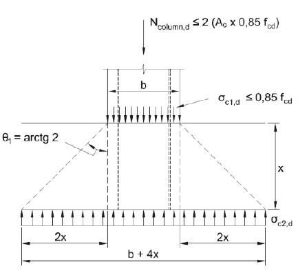
The geometry of the node at the base of the column assumes a 63.4° spreading load (see Figure 5). Additionally, for the design of the pile cap, [5[5] FUSCO, P. B. (1995). Técnicas de armar as estruturas de concreto. Editora PINI, São Paulo.] considers that the column load is the design compression resistance of the column. In addition, [5[5] FUSCO, P. B. (1995). Técnicas de armar as estruturas de concreto. Editora PINI, São Paulo.] defines a depth x of the top node in which the vertical stress in the spreading area is equal to:
Basic behavior of pile caps (FUSCO [5[5] FUSCO, P. B. (1995). Técnicas de armar as estruturas de concreto. Editora PINI, São Paulo.])
Stresses in the horizontal plan of the pile cap (FUSCO [5[5] FUSCO, P. B. (1995). Técnicas de armar as estruturas de concreto. Editora PINI, São Paulo.])
The horizontal plane in which the vertical stress equals 20% of the design value of concrete compressive strength is justified, since [5[5] FUSCO, P. B. (1995). Técnicas de armar as estruturas de concreto. Editora PINI, São Paulo.] limited the compressive stresses in the concrete struts in fcd and imposed the minimum inclination angle of the diagonal strut (i.e. θ = 26.6°). Thus, the verification of safety against crushing concrete strut is ensured by checking if the inclination angles of the diagonal struts is higher than the recommend value of 33.7º (arctan 2/3). Following the determination of this plan, the Fusco method can be assumed equivalent to the Blévot method with fictional enlarged column (Ac,sp) and smaller effective depth (d-x), then:
Where,
The crushing strength of concrete strut equals fcd; according to [5[5] FUSCO, P. B. (1995). Técnicas de armar as estruturas de concreto. Editora PINI, São Paulo.], it is conservative because of the confinement in a partially loaded area.
Fusco [5[5] FUSCO, P. B. (1995). Técnicas de armar as estruturas de concreto. Editora PINI, São Paulo.] considers that the reinforcement contributes to the design compression resistance of the column; it is thus necessary to transfer the forces between steel bar and concrete within the pile cap. According to [5[5] FUSCO, P. B. (1995). Técnicas de armar as estruturas de concreto. Editora PINI, São Paulo.], short bond lengths of 10 to 15 diameters of the bars are perfectly feasible.
In order to simplify the determination of the depth in which the verIn order to simplify the determination of the depth in which the vertical tension is equal to 0.2 fcd, [5[5] FUSCO, P. B. (1995). Técnicas de armar as estruturas de concreto. Editora PINI, São Paulo.] determined values of x depending on the longitudinal reinforcement ratio in the column (Figure 6).
Strength of the diagonal strut below the column (FUSCO [5[5] FUSCO, P. B. (1995). Técnicas de armar as estruturas de concreto. Editora PINI, São Paulo.])
At the top of the piles (Figure 7), the stresses in the concrete struts depend of the spreading area of the pile until the plane of the reinforcement, where the equilibrium between concrete strut, pile reaction and reinforcement is obtained.
Strength of the diagonal strut above the piles (Fusco [5[5] FUSCO, P. B. (1995). Técnicas de armar as estruturas de concreto. Editora PINI, São Paulo.])
The method assumes that the distance between the reinforcement and the base of the pile cap is approximately:
Thus, the spreading diameter (or side) of the pile is:
Since the crushing strength of the diagonal strut is assumed to be fcd, it is possible, in a similar way to that of the node at the base of the column, to indirectly limit the stress in the concrete strut by:
Where npile is the number of piles in the pile cap and Ap,sp is the spreading area of the pile.
Although the node at the base of the column assumes a 63.4° spreading load, at the top of the piles, Fusco [5[5] FUSCO, P. B. (1995). Técnicas de armar as estruturas de concreto. Editora PINI, São Paulo.] recommends a 45° spreading of the pile reaction.
The Fusco method can be considered an adaptation of the Blévot method by replacing the actual areas of the column and piles for the correspondent spreading areas. The use of the spreading areas results in lower stresses in the concrete struts when compared to the Blévot method and allows using the design strength of concrete struts and the design values of stresses within the nodes, which is permitted in the codes and standards. Nevertheless, it is important to note that these limits do not generally consider confinement (they are valid for plane elements).
3.3 Adebar e Zhou (1996)
Adebar and Zhou ([7[7] ADEBAR, P.; ZHOU, Z. (1993). Bearing strength of compressive struts confined by plain concrete. ACI Journal, v. 90, n.5, p.534-541.] and [8[8] ADEBAR, P.; ZHOU, Z. (1996). Design of deep pile caps by strut-and-tie models. ACI Journal, v. 93, n.4, p.1-12.]) proposed a design method based on analytical and experimental studies of bearing strength of compressive struts confined by plain concrete. They suggested that when designing deep pile cap without sufficient reinforcement to ensure redistribution of internal forces after cracking, the maximum bearing stress should be limited to
Where
f'c - specified compressive strength of concrete (according to ACI 318 [19[19] ACI COMMITTEE 318 (2014). Building Code Requirements for Structural Concrete: (ACI 318-14) and Commentary. Farmington Hills, MI: American Concrete Institute.]);
Parameter α accounts for the confinement of the compression strut. The ratio A2/A1 is similar to the ratio Ac1/Ac0 of NBR 6118 [4[4] ASSOCIAÇÃO BRASILEIRA DE NORMAS TÉCNICAS (2014). NBR6118 - Projeto de estruturas de concreto - Procedimento. Rio de Janeiro.] for local crushing in partially loaded area. Parameter β accounts for the geometry of the compression strut. To calculate the bearing strength of the nodal zone at the base of the column, where two or more compression struts meet, the ratio hs/bs can be approximated as ([8[8] ADEBAR, P.; ZHOU, Z. (1996). Design of deep pile caps by strut-and-tie models. ACI Journal, v. 93, n.4, p.1-12.]).
Where ac is the dimension of a square column.
To calculate the bearing strength of the nodal zone above a pile, where only one compression strut is anchored, the ratio hs/bs can be approximated as ([8[8] ADEBAR, P.; ZHOU, Z. (1996). Design of deep pile caps by strut-and-tie models. ACI Journal, v. 93, n.4, p.1-12.]).
where apile is the diameter of a round pile or the dimension of a square pile.
The proposed strut-and-tie model approach is intended for designing deep pile caps, rather than slender pile caps ([8[8] ADEBAR, P.; ZHOU, Z. (1996). Design of deep pile caps by strut-and-tie models. ACI Journal, v. 93, n.4, p.1-12.]). The researchers recognize that it is difficult to separate the two types and some pile caps may be somewhere in between.
The methodology proposed in [7[7] ADEBAR, P.; ZHOU, Z. (1993). Bearing strength of compressive struts confined by plain concrete. ACI Journal, v. 90, n.5, p.534-541.] and [8[8] ADEBAR, P.; ZHOU, Z. (1996). Design of deep pile caps by strut-and-tie models. ACI Journal, v. 93, n.4, p.1-12.] is not clear about which lever arm should be used for determining the reinforcement; hence, this method was not compared with the test results (Tables 1 and 2).
3.4 Santos et al. [3[3] Santos, D. M.; Marquesi, M. L.; Stucchi, F. R. (2015). Dimensionamento de blocos de fundações sobre 2 e 4 estacas. In: ABNT NBR 6118:2014 comentários e exemplos de aplicação. IBRACON, 455-478, São Paulo.]
The recently developed model by Santos et al. [3[3] Santos, D. M.; Marquesi, M. L.; Stucchi, F. R. (2015). Dimensionamento de blocos de fundações sobre 2 e 4 estacas. In: ABNT NBR 6118:2014 comentários e exemplos de aplicação. IBRACON, 455-478, São Paulo.] combined the simplified equations of bearing stresses of the Blévot model with the concept of spreading the load of the Fusco model.
This model was developed from the need to use the prescriptions of the Brazilian standard. The design strength of concrete struts and the design values of the compressive stress within nodes in NBR6118 [4[4] ASSOCIAÇÃO BRASILEIRA DE NORMAS TÉCNICAS (2014). NBR6118 - Projeto de estruturas de concreto - Procedimento. Rio de Janeiro.] are based on tests in plane elements. However, the proposed model is more general and not limited to specific values.
The model adapts the classical method with the more consistent consideration of the geometry of the node below the column. In addition, a small adjustment was proposed in the stress verification within the nodes above the piles, based on the recommendation of Fusco [5[5] FUSCO, P. B. (1995). Técnicas de armar as estruturas de concreto. Editora PINI, São Paulo.], as shown in Figure 8.
Strut-and-tie model with the compressive node inside the pile cap (SANTOS et al. [3[3] Santos, D. M.; Marquesi, M. L.; Stucchi, F. R. (2015). Dimensionamento de blocos de fundações sobre 2 e 4 estacas. In: ABNT NBR 6118:2014 comentários e exemplos de aplicação. IBRACON, 455-478, São Paulo.])
The bearing stress can be estimated by adapting equations (5) and (6). In this method, the area of the piles and column are replaced by the 45 spreading area, which allows a more rational way of determining the compressive strut area in the node regions. The ideal angle for spreading the load is the same as the angle of inclination of the diagonal struts; however, in more complex geometries, in which the struts do not have the same angle of inclination, the 45 spreading load seems to simplify the model without significant losses of precision.
A comparison between the geometries of the Blévot model and the strut-and-tie models (STM) proposed by Schlaich et al. [20[20] SCHLAICH, J.; SCHÄFER, K.; JENNEWEIN, M. (1987). Toward a consistent design of structural concrete. PCI Journal, v.32, n.3; p.75-150.] is depicted in Figure 9, which shows that the models define inclinations of diagonal struts in different ways. While the “Blévot method” defines the tangent of the angle by the ratio d ⁄ Lproj, the STM defines by z ⁄ Lproj, where, z = d - 0.5y and y is the depth of the neutral axis or the depth of the node below the column.
Comparisons between strut-and-tie models and Blévot e Frémy [1[1] BLEVOT, J.; FRÉMY, R. (1967). Semelles sur pieux. Analles de l’Institut Technique du Batiment et des Travaux Publics., Paris, v.20, n.230.] model (SANTOS et al. [3[3] Santos, D. M.; Marquesi, M. L.; Stucchi, F. R. (2015). Dimensionamento de blocos de fundações sobre 2 e 4 estacas. In: ABNT NBR 6118:2014 comentários e exemplos de aplicação. IBRACON, 455-478, São Paulo.])
To prevent crushing of the diagonal strut of concrete, [3[3] Santos, D. M.; Marquesi, M. L.; Stucchi, F. R. (2015). Dimensionamento de blocos de fundações sobre 2 e 4 estacas. In: ABNT NBR 6118:2014 comentários e exemplos de aplicação. IBRACON, 455-478, São Paulo.] establishes the limits below:
Where,
fcd1 = 0,85 ∙ αv2 ∙ fcd;
fcd3 = 0,72 ∙ αv2 ∙ fcd;
αv2 = 1 - fck ⁄ 250, fckk em MPa;
Ap,sp = , for round pile, and Ap,sp = (apile + 2d')2, for square pile;
Ac,sp = (ac + 2y)(bc + 2y), for rectangular column.
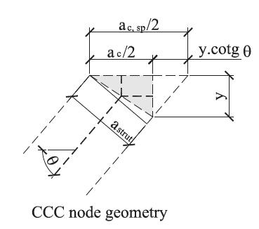
Although there are similarities with the Fusco model, the STM proposed by Santos et al. [3[3] Santos, D. M.; Marquesi, M. L.; Stucchi, F. R. (2015). Dimensionamento de blocos de fundações sobre 2 e 4 estacas. In: ABNT NBR 6118:2014 comentários e exemplos de aplicação. IBRACON, 455-478, São Paulo.] is not equivalent to the classical model replacing the area of the column for a spreading area. The spreading area is only a way to estimate the compression stresses in the struts. The proposal is based on the equivalence, in plane elements, of calculating the width of the diagonal strut by the geometry of the node or by the concept of spreading load, with a spreading angle equal to that of the diagonal strut, i. e. (Figure 10):
Equivalence between spreading of the load and node geometry proposed by Schlaich et al. [20[20] SCHLAICH, J.; SCHÄFER, K.; JENNEWEIN, M. (1987). Toward a consistent design of structural concrete. PCI Journal, v.32, n.3; p.75-150.]
The design values of the compressive stress within the node below the column is adopted, in a conservative way, as the value established in item 22.1 of NBR 6118 [4[4] ASSOCIAÇÃO BRASILEIRA DE NORMAS TÉCNICAS (2014). NBR6118 - Projeto de estruturas de concreto - Procedimento. Rio de Janeiro.] for CCC node, and it is independent of the number of piles. The nodes above the piles are considered as CCT.
Since the crushing strengths adopted do not consider any confinement by the triaxial compression or by plain concrete, comparisons with the test data were performed with two different limits for the node at the top: 0.85 ∙ fcd and fcd1. The effectiveness factor αv2 was eliminated in one of the assessments.
The method consists in determining the depth of the CCC node below the column in an iterative manner, until the stress within the node (or in the concrete struts) is equal to the design value of the crushing strength. The calculation procedure is:
-
Define the initial depth of the top node (e. g., y = 0,2d);
-
Determine θ (recommendation: θ ≥ 45°);
-
Determine the design compressive stress within the node
-
If the design compressive stress within the node is different from the design value of the crushing strength, update y until σcd,c = fcd1;
-
Determine θ with the final value of y and the main reinforcement;
-
Check if the design stress within the node above the piles is limited to fcd3;
-
Determine the secondary distributed reinforcement for cracking control.
The Santos et al. [3[3] Santos, D. M.; Marquesi, M. L.; Stucchi, F. R. (2015). Dimensionamento de blocos de fundações sobre 2 e 4 estacas. In: ABNT NBR 6118:2014 comentários e exemplos de aplicação. IBRACON, 455-478, São Paulo.] strut-and-tie model, in comparison with the classical method [1[1] BLEVOT, J.; FRÉMY, R. (1967). Semelles sur pieux. Analles de l’Institut Technique du Batiment et des Travaux Publics., Paris, v.20, n.230.], results in higher amounts of reinforcement. The only possible exception is for two-pile caps due to the factor of 1.15 proposed by Blévot and Frémy [1[1] BLEVOT, J.; FRÉMY, R. (1967). Semelles sur pieux. Analles de l’Institut Technique du Batiment et des Travaux Publics., Paris, v.20, n.230.].
3.5 Some differences between models
The Santos et al. [3[3] Santos, D. M.; Marquesi, M. L.; Stucchi, F. R. (2015). Dimensionamento de blocos de fundações sobre 2 e 4 estacas. In: ABNT NBR 6118:2014 comentários e exemplos de aplicação. IBRACON, 455-478, São Paulo.] model assumes sufficient redistribution capacity of internal forces so that the Ultimate Limit State (ULS) is achieved only when the reinforcement and the node below the column reach their design strength limit.
This hypothesis is adequate only if the concrete strut and the node above the piles do not crush before the yielding of the reinforcement, since the redistribution capacity of internal forces depends on the plastic deformation of the steel.
The Santos et al. [3[3] Santos, D. M.; Marquesi, M. L.; Stucchi, F. R. (2015). Dimensionamento de blocos de fundações sobre 2 e 4 estacas. In: ABNT NBR 6118:2014 comentários e exemplos de aplicação. IBRACON, 455-478, São Paulo.] model has similarities with the bending theory and, equivalently, it is necessary to ensure sufficient capacity of plastic deformation. This can be done in a simplified way, as is common in the design of beams, by limiting the depth of the neutral axis (or depth of CCC node). Preliminary studies on test data of pile caps with brittle failure show that the ratio limit y/d not greater than 0.3 is adequate.
In contrast, the Blévot and Frémy [1[1] BLEVOT, J.; FRÉMY, R. (1967). Semelles sur pieux. Analles de l’Institut Technique du Batiment et des Travaux Publics., Paris, v.20, n.230.] model assumes that the angle of the diagonal strut is determined only by geometrical data, thus implying that three separate limit states exist: when the design value of stresses in the node below the column or in the node above the piles or in the reinforcement reached the design compressive/tension strength.
When designing the pile caps by the classical method, if the ultimate limit state is exceeded in one of the nodes (i.e. in the diagonal strut), only by changing the geometry of the pile cap (height, for example) or the strength of the concrete can the problem be solved. However, in the Santos et al. [3[3] Santos, D. M.; Marquesi, M. L.; Stucchi, F. R. (2015). Dimensionamento de blocos de fundações sobre 2 e 4 estacas. In: ABNT NBR 6118:2014 comentários e exemplos de aplicação. IBRACON, 455-478, São Paulo.] model, for the same column force, these parameters may be the same by increasing the amount of reinforcement. In this case, the flexural strength of the pile cap grows with the increments of the tension forces in the reinforcement and of the compressive forces in the node below the column, despite the decreases in the lever arm.
The differences between the two models is very important, as increasing the strength of the concrete or the geometry of the pile cap can be costly.
The Fusco [5[5] FUSCO, P. B. (1995). Técnicas de armar as estruturas de concreto. Editora PINI, São Paulo.] model also assumes that the strength of the node at the base of the column depends on the quantity of reinforcement. However, since the angle of spreading the load is very large, the angle of inclination of the diagonal strut could be greater than the angle defined by the classical model, which produces unrealistic geometry of the strut-and-tie model allowing tensile stresses in the upper region of the pile caps (Figure 11).
Possible stress field by the Fusco [5[5] FUSCO, P. B. (1995). Técnicas de armar as estruturas de concreto. Editora PINI, São Paulo.] model
The Fusco model was idealized for angles of the diagonal struts of 33.7° (arctg 2/3). In order to eliminate the problem illustrated in Figure 11, the spreading load could be smaller for larger angles; however, comparisons with the tests was performed with the original prescriptions.
4. Comparative study
Table 3 presents the ratio of measured pile cap capacity to predicted capacity for the models mentioned above (except for the Zhou and Adebar [8[8] ADEBAR, P.; ZHOU, Z. (1996). Design of deep pile caps by strut-and-tie models. ACI Journal, v. 93, n.4, p.1-12.] model). The Santos et al. [3[3] Santos, D. M.; Marquesi, M. L.; Stucchi, F. R. (2015). Dimensionamento de blocos de fundações sobre 2 e 4 estacas. In: ABNT NBR 6118:2014 comentários e exemplos de aplicação. IBRACON, 455-478, São Paulo.] model is shown twice because one of them did not use the effectiveness factor in the crushing strength of the concrete strut.
It interesting to note that the classical model [1[1] BLEVOT, J.; FRÉMY, R. (1967). Semelles sur pieux. Analles de l’Institut Technique du Batiment et des Travaux Publics., Paris, v.20, n.230.] and the Santos et al. [3[3] Santos, D. M.; Marquesi, M. L.; Stucchi, F. R. (2015). Dimensionamento de blocos de fundações sobre 2 e 4 estacas. In: ABNT NBR 6118:2014 comentários e exemplos de aplicação. IBRACON, 455-478, São Paulo.] model have similar predictions, and that the Fusco model was conservative due to the simplified verification above the piles. Moreover, in some of the pile caps tested, it was not possible to determine x (depth of load spreading).
Table 4 summarizes the predicted failure mode. In the “Blévot model” there are three possible failure modes, which are: yielding of reinforcement (Reinf. In Table 4), crushing of the node below the column (Column) or crushing of the node above the piles (pile). In the model proposed by Santos et al. [3[3] Santos, D. M.; Marquesi, M. L.; Stucchi, F. R. (2015). Dimensionamento de blocos de fundações sobre 2 e 4 estacas. In: ABNT NBR 6118:2014 comentários e exemplos de aplicação. IBRACON, 455-478, São Paulo.] (and Fusco [5[5] FUSCO, P. B. (1995). Técnicas de armar as estruturas de concreto. Editora PINI, São Paulo.] model), generally, there are only two failure modes: (Reinf./Column) crushing of the upper node after the yielding of the reinforcement or crushing of lower node without reinforcement yielding (pile).
In addition, it is noticed that the coefficients of variation (cv) are high, showing the complexity of the problem. Park et al. [18[18] PARK, J., KUCHMA, D. e SOUZA, R. (2008). Strength predictions of pile caps by a strut-and-tie model approach. Canadian Journal of Civil Engineering, v. 31, n.1, p.109-119.] and Adebar and Zhou [8[8] ADEBAR, P.; ZHOU, Z. (1996). Design of deep pile caps by strut-and-tie models. ACI Journal, v. 93, n.4, p.1-12.] compared some experiments with the theoretical results of strut-and-tie models and the bending theory (slab analogy), and even with relatively high cv, the STM showed more reliable predictions.
In Table 5, the statistical parameters are calculated assuming separate groups of tests by researcher. This analysis shows significant differences in the prediction of the failure load when only the assays of Susuki et al. [10[10] SUZUKI, K.; OTSUKI, K.; TSUBATA, T. (1998). Influence of bar arrangement on ultimate strength of four pile caps. Transactions of the Japan Concrete Institute, V. 20, pp. 195-202.] is selected. For the test data of Blévot and Frémy [1[1] BLEVOT, J.; FRÉMY, R. (1967). Semelles sur pieux. Analles de l’Institut Technique du Batiment et des Travaux Publics., Paris, v.20, n.230.] and Clarke [9[9] CLARKE, J. L. (1973). Behavior and design of pile caps with four piles. Cement and concrete association, London, 19p. (Technical Report, n. 42.489).], again the predictions load by [1[1] BLEVOT, J.; FRÉMY, R. (1967). Semelles sur pieux. Analles de l’Institut Technique du Batiment et des Travaux Publics., Paris, v.20, n.230.] and [3[3] Santos, D. M.; Marquesi, M. L.; Stucchi, F. R. (2015). Dimensionamento de blocos de fundações sobre 2 e 4 estacas. In: ABNT NBR 6118:2014 comentários e exemplos de aplicação. IBRACON, 455-478, São Paulo.] are similar, the Fusco model remains conservative.
Within the selected tests of [1[1] BLEVOT, J.; FRÉMY, R. (1967). Semelles sur pieux. Analles de l’Institut Technique du Batiment et des Travaux Publics., Paris, v.20, n.230.], there are 4 specimens (11,1a, 11,1b, 11,2a and 11,2b) in that the predictions by STM were very unsafe. Blévot and Frémy ([1[1] BLEVOT, J.; FRÉMY, R. (1967). Semelles sur pieux. Analles de l’Institut Technique du Batiment et des Travaux Publics., Paris, v.20, n.230.]) describe that the failures of these pile caps occurred with large vertical and inclined cracking, typical of brittle failure. This behavior may indicate a slipping of the reinforcement due to insufficient anchorage length. The mean value and the coefficient of variation of the ratio between experimental load and theoretical load, without these tests, are equal to: 1.14 and 0.09, for [1[1] BLEVOT, J.; FRÉMY, R. (1967). Semelles sur pieux. Analles de l’Institut Technique du Batiment et des Travaux Publics., Paris, v.20, n.230.] model; 1.20 and 0.08, for [3[3] Santos, D. M.; Marquesi, M. L.; Stucchi, F. R. (2015). Dimensionamento de blocos de fundações sobre 2 e 4 estacas. In: ABNT NBR 6118:2014 comentários e exemplos de aplicação. IBRACON, 455-478, São Paulo.] (without the effectiveness factor). The improvement in the prediction of both models was expected (due to a reduction in the standard deviation).
The assays performed by Susuki et al. [10[10] SUZUKI, K.; OTSUKI, K.; TSUBATA, T. (1998). Influence of bar arrangement on ultimate strength of four pile caps. Transactions of the Japan Concrete Institute, V. 20, pp. 195-202.] had large columns resulting in failure by bending with relatively low vertical stresses within the column (even for failure load) compared to the compressive concrete strength. Table 5 allows observing that the Santos et al. method [3[3] Santos, D. M.; Marquesi, M. L.; Stucchi, F. R. (2015). Dimensionamento de blocos de fundações sobre 2 e 4 estacas. In: ABNT NBR 6118:2014 comentários e exemplos de aplicação. IBRACON, 455-478, São Paulo.] becomes equivalent to the classical method, since even with y equal to zero, the crushing strength of the diagonal strut is higher than the internal force in the concrete.
The conservatism observed from Suzuki’s tests suggests that the strut-and-tie model to be used differs from the discussed models, i.e., this case is outside the method applicability, although they can be used in a conservative way. A more suitable strut-and-tie model is illustrated in Figure 11.
Since the Fusco model was overly conservative, given the limitation of the vertical stresses in the spreading area of the piles, a more refined analysis was performed in which the stresses within the diagonal strut above the piles was limited in f cd. The summary of the two analyses is shown in Table 6.
The model proposed by Fusco [5[5] FUSCO, P. B. (1995). Técnicas de armar as estruturas de concreto. Editora PINI, São Paulo.] was very sensitive to the spreading pile area used, for example, in the scale reduced tests performed by [1[1] BLEVOT, J.; FRÉMY, R. (1967). Semelles sur pieux. Analles de l’Institut Technique du Batiment et des Travaux Publics., Paris, v.20, n.230.] (Figure 2). It was considered that it is not possible to spread the load, considering that the distance from the edge of the pile to the edge of the pile cap is 2 cm of unreinforced concrete. If this 2 cm are considered in the spreading area, the bearing capacity of the pile cap increases 65%, which significantly improves the prediction regarding this group of tests.
Strut-and-tie models for two-pile caps: a) The stress in the column is equal to the strength of concrete and b) The stress in the column is lower than the strength of concrete
5. Conclusions
In this study, four strut-and-tie models applied to pile caps were analyzed, and three of them were compared with experimental results.
The classical method (Blévot and Frémy [1[1] BLEVOT, J.; FRÉMY, R. (1967). Semelles sur pieux. Analles de l’Institut Technique du Batiment et des Travaux Publics., Paris, v.20, n.230.]), which is widely used in Brazil, showed adequate predictions, albeit sometimes conservative. This model determines the stresses in the concrete diagonal strut in a conventional form, resulting in very high stresses in relation to the strength of concrete.
The Fusco model [5[5] FUSCO, P. B. (1995). Técnicas de armar as estruturas de concreto. Editora PINI, São Paulo.] is based on the classical model and introduces the concept of spreading the load, in order to more realistically determine the compressive stresses in the diagonal strut. Comparisons with assays show that the model is very sensitive to the spreading area. Additionally, Fusco [5[5] FUSCO, P. B. (1995). Técnicas de armar as estruturas de concreto. Editora PINI, São Paulo.] idealized the model for angles of inclination about 33.7°; since the majority of the tests had higher inclinations, the predictions of this model were very conservative.
The model recently presented by Santos et al. [3[3] Santos, D. M.; Marquesi, M. L.; Stucchi, F. R. (2015). Dimensionamento de blocos de fundações sobre 2 e 4 estacas. In: ABNT NBR 6118:2014 comentários e exemplos de aplicação. IBRACON, 455-478, São Paulo.] mixed the Blévot and Frémy [1[1] BLEVOT, J.; FRÉMY, R. (1967). Semelles sur pieux. Analles de l’Institut Technique du Batiment et des Travaux Publics., Paris, v.20, n.230.] model with the Fusco [5[5] FUSCO, P. B. (1995). Técnicas de armar as estruturas de concreto. Editora PINI, São Paulo.] spreading load concept. This is consistent with the theoretical concepts of strut-and-tie models and stress fields. Experimental comparisons show that the predictions of this model are similar to the classical method, i.e., it is also adequate for designing pile caps.
The safety level of the model recently proposed by Santos et al. [3[3] Santos, D. M.; Marquesi, M. L.; Stucchi, F. R. (2015). Dimensionamento de blocos de fundações sobre 2 e 4 estacas. In: ABNT NBR 6118:2014 comentários e exemplos de aplicação. IBRACON, 455-478, São Paulo.] is equivalent to the safety level of the Blévot and Frémy [5[5] FUSCO, P. B. (1995). Técnicas de armar as estruturas de concreto. Editora PINI, São Paulo.] model, widely and successfully used in Brazil. However, the great difference between the two methods could not be evidenced by the available tests, since the mechanical ratio of reinforcement in the specimens was not high.
The Santos et al. [3[3] Santos, D. M.; Marquesi, M. L.; Stucchi, F. R. (2015). Dimensionamento de blocos de fundações sobre 2 e 4 estacas. In: ABNT NBR 6118:2014 comentários e exemplos de aplicação. IBRACON, 455-478, São Paulo.] model can be used with the design strength of concrete struts and the design values of the compressive stress within nodes by the Brazilian standard (calibrated for plane elements) without excessive conservatism in comparison with the Blévot and Frémy [5[5] FUSCO, P. B. (1995). Técnicas de armar as estruturas de concreto. Editora PINI, São Paulo.] model.
Comparisons with experimental results indicate that the elimination of the effectiveness coefficient is feasible, which is proposed as an improvement to the Santos el al. [3[3] Santos, D. M.; Marquesi, M. L.; Stucchi, F. R. (2015). Dimensionamento de blocos de fundações sobre 2 e 4 estacas. In: ABNT NBR 6118:2014 comentários e exemplos de aplicação. IBRACON, 455-478, São Paulo.] model.
6. References
-
[1]BLEVOT, J.; FRÉMY, R. (1967). Semelles sur pieux. Analles de l’Institut Technique du Batiment et des Travaux Publics., Paris, v.20, n.230.
-
[2]COMITÉ EURO-ITERNATIONAL DU BÉTON (1970). CEB-FIP Recommandations particulières au calcul et à l’execution des semelles de fondation. Bulletin d’Information, Paris, n.73.
-
[3]Santos, D. M.; Marquesi, M. L.; Stucchi, F. R. (2015). Dimensionamento de blocos de fundações sobre 2 e 4 estacas. In: ABNT NBR 6118:2014 comentários e exemplos de aplicação. IBRACON, 455-478, São Paulo.
-
[4]ASSOCIAÇÃO BRASILEIRA DE NORMAS TÉCNICAS (2014). NBR6118 - Projeto de estruturas de concreto - Procedimento. Rio de Janeiro.
-
[5]FUSCO, P. B. (1995). Técnicas de armar as estruturas de concreto. Editora PINI, São Paulo.
-
[6]ADEBAR, P.; KUCHMA, D.; COLLINS, M. P. (1990). Strut-and-tie models for design of pile caps: An experimental study. ACI Journal, v. 87, n.1, p.81-91.
-
[7]ADEBAR, P.; ZHOU, Z. (1993). Bearing strength of compressive struts confined by plain concrete. ACI Journal, v. 90, n.5, p.534-541.
-
[8]ADEBAR, P.; ZHOU, Z. (1996). Design of deep pile caps by strut-and-tie models. ACI Journal, v. 93, n.4, p.1-12.
-
[9]CLARKE, J. L. (1973). Behavior and design of pile caps with four piles. Cement and concrete association, London, 19p. (Technical Report, n. 42.489).
-
[10]SUZUKI, K.; OTSUKI, K.; TSUBATA, T. (1998). Influence of bar arrangement on ultimate strength of four pile caps. Transactions of the Japan Concrete Institute, V. 20, pp. 195-202.
-
[11]SUZUKI, K.; OTSUKI, K.; TSUBATA, T. (1999). Experimental Study on Four-Pile Caps with Taper. Transactions of the Japan Concrete Institute, V. 21, pp. 327-334.
-
[12]SUZUKI, K.; OTSUKI, K.; TSUHIYA, T. (2000). Influence of Edge Distance on Failure Mechanism of Pile Caps. Transactions of the Japan Concrete Institute, V. 22, pp. 361-36.
-
[13]SUZUKI, K., and OTSUKI, K., (2002). Experimental Study on Corner Shear Failure of Pile Caps, Transactions of the Japan Concrete Institute, V. 23, 2002
-
[14]CAO, J. (2009). The shear behavior of the reinforced concrete four-pile caps. University of Southampton, United Kingdom, PhD Thesis.
-
[15]MIGUEL, G. M. (2000). Análise experimental e numérica de blocos sobre três estacas. Tese (doutorado) - Escola de Engenharia de São Carlos, Universidade de São Paulo, São Carlos, SP.
-
[16]BARROS, R. (2013). Análise numérica experimental de blocos de concreto armado sobre duas estacas com cálice externo, parcialmente embutido e embutido utilizado na ligação pilar-fundação. Tese (doutorado) - Escola de Engenharia de São Carlos, Universidade de São Paulo, São Carlos, SP.
-
[17]MUNHOZ, F. S. (2014). Análise experimental e numérica de blocos rígidos sobre duas estacas com pilares de seções quadradas e retangulares e diferentes taxas de armadura. Tese (doutorado) - Escola de Engenharia de São Carlos, Universidade de São Paulo, São Carlos, SP.
-
[18]PARK, J., KUCHMA, D. e SOUZA, R. (2008). Strength predictions of pile caps by a strut-and-tie model approach. Canadian Journal of Civil Engineering, v. 31, n.1, p.109-119.
-
[19]ACI COMMITTEE 318 (2014). Building Code Requirements for Structural Concrete: (ACI 318-14) and Commentary. Farmington Hills, MI: American Concrete Institute.
-
[20]SCHLAICH, J.; SCHÄFER, K.; JENNEWEIN, M. (1987). Toward a consistent design of structural concrete. PCI Journal, v.32, n.3; p.75-150.
-
[21]MUTTONI, A.; SCHWARTZ, J.; THÜRLIMANN B. (1997). Design of concrete structures with stress fields. Birkhäuser, 143p.
-
[22]CARVALHO, M. L. (2018). Análise de confiabilidade de modelos de capacidade resistente de blocos de fundação. Dissertação (mestrado) - Escola Politécnica da Universidade de São Paulo, São Paulo, SP.
Publication Dates
-
Publication in this collection
23 Sept 2019 -
Date of issue
Jul-Aug 2019
History
-
Received
29 June 2017 -
Accepted
26 Sept 2018 -
Published
08 Aug 2019