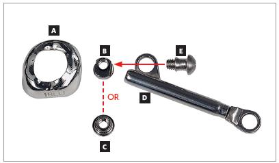
Figure 1
Miniscope telescopic system: A) Rollo band; B) Universal nut; C) Barrel nut; D) Miniscope (right side); E) Applecore screw.
Figure 2
An illustration of true stimulation and temporary stimulation of mandibular growth. True stimulation indicates that growth occurs at a faster-than-expected rate during functional appliance therapy, then continues at the expected rate thereafter, so that the ultimate size of the mandible is larger. Temporary acceleration means that faster growth occurs during functional therapy, but slower growth thereafter ultimately brings the mandible back to the size that would be expected without treatment (Adapted from:Lai and McNamara23, 1998).
Figure 3
Tridimensional assessment carried out by means of colored maps after one year of treatment with the Herbst appliance: A) frontal view; B) lateral view; C) lateral view of mesh superimposition; D) mandibular occlusal view.
Figure 4
TMJ laminagraphic images of patient treated with Cantilever Bite Jumper (CBJ). A) Before treatment onset, condyles were centered in the fossa. At appliance placement, the mandible was moved 9mm (07/08) forward. Two and four months later, double condyle and mandibular fossa images are seen as a result of bone remodeling. B) Seven months later (11/03), the condyle was back to its primary position.
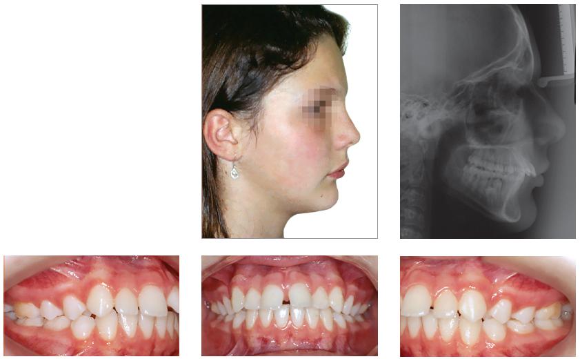
Figure 5
Pretreatment records: Extra and intraoral photographs, and lateral cephalogram.
Figure 6
Intraoral right photograph showing Herbst appliance placement.
Figure 7
Intraoral right photograph showing fixed appliance.
Figure 8
Posttreatment records: Extra and intraoral photographs, and lateral cephalogram.
Figure 9
Posttreatment records at ten years: Extra and intraoral photographs, and lateral cephalogram.
Figure 10
A) Cephalometric tracings superimposition on the cranial base (black = initial; blue = after Herbst appliance; red = treatment completion; green = ten years after treatment completion). B) Maxillary superimposition (ANS-PNS registered at ANS). C) Mandibular superimposition (Xi-Pm registered at Pm).
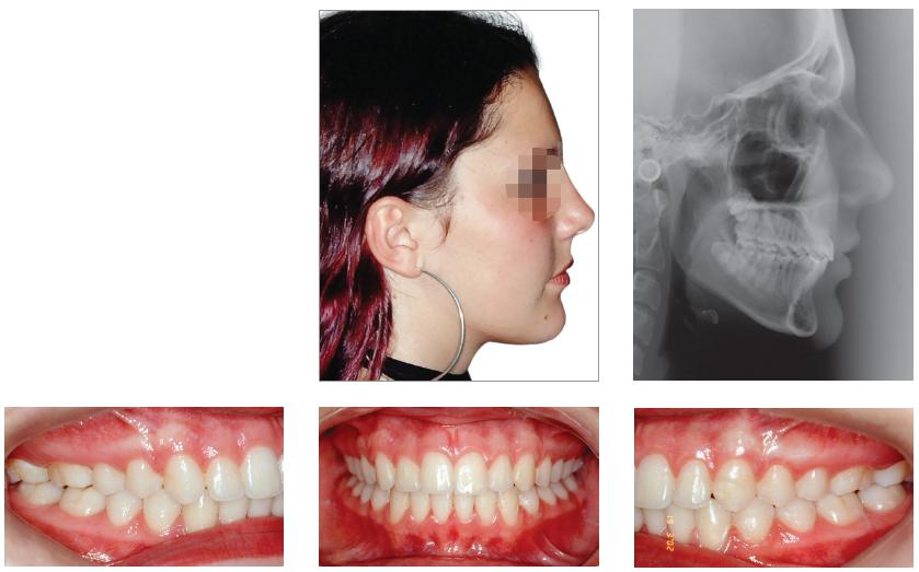
Figure 11
Pretreatment records: Extra and intraoral photographs, and lateral cephalogram.
Figure 12
Intraoral right photograph after Herbst appliance placement.
Figure 13
Intraoral right photograph showing fixed appliance.
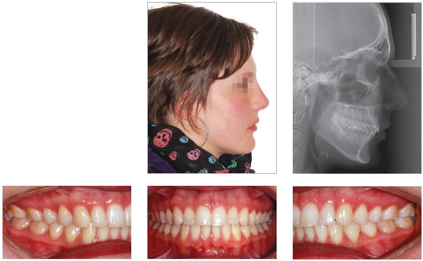
Figure 14
Posttreatment records: Extra and intraoral photographs, and lateral cephalogram.
Figure 15
A) Cephalometric tracings superimposition on the cranial base (black = initial; blue = after Herbst appliance; red = treatment completion). B) Maxillary superimposition (ANS-PNS registered at ANS). C) Mandibular superimposition (Xi-Pm registered at Pm).
Figure 16
Posttreatment records at 5.5 years: Extra and intraoral photographs.
Figure 17
Forsus Fatigue Resistant Device with L-pin Module, released in 2002.
Figure 18
Forsus Fatigue Resistant Device with EZ2 Module. Note two screws on maxillary molar clip (modification released in 2009).
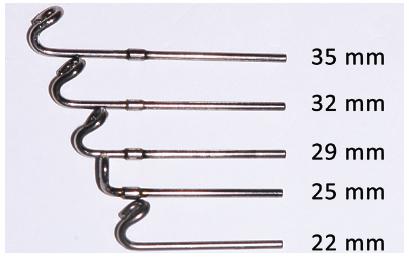
Figure 19
Forsus appliance push rods in different sizes: extra short push rod = 22 mm; short push rod = 25 mm; median push rod: 29 mm; large push rod = 32 mm; extralarge push rod = 35 mm.
Figure 20
Measurement gauge placement. The tool is used to choose the size of Forsus appliance. With the patient biting and having the mandible in maximal intercuspation, the clinician places the buccal portion of the measurement gauge behind the maxillary molar tube. The tool is then tipped and the number near the distal portion of the canine bracket or mandibular first premolar is chosen.
Figure 21
Plastic caps used to protect patient’s cheek when Forsus appliance is used.
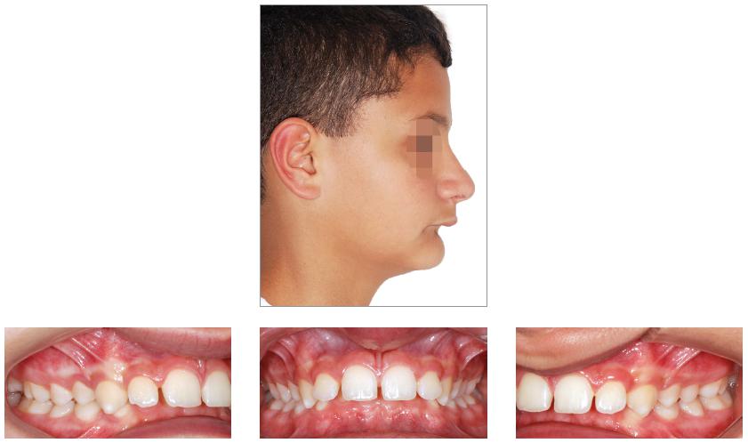
Figure 22
Pretreatment records: Extra and intraoral photographs.
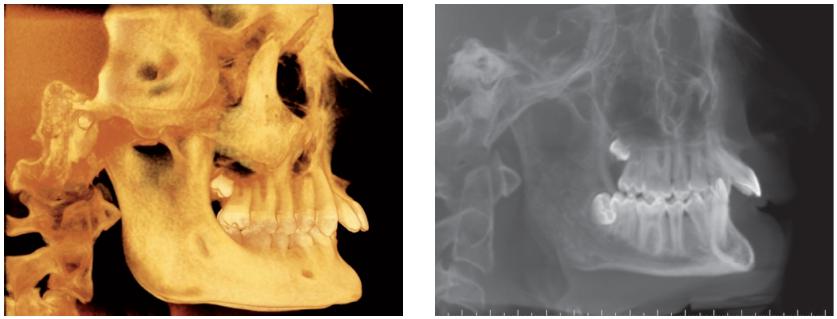
Figure 23
Initial tomographic scan in lateral view and lateral cephalogram.
Figure 24
Intraoral photograph showing X-bow placement.
Figure 25
Intraoral photograph showing fixed appliance.
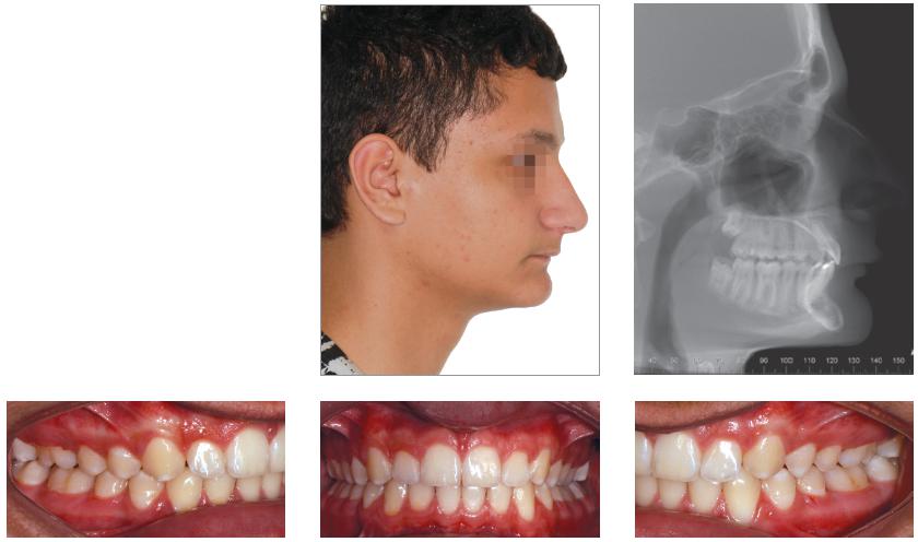
Figure 26
Posttreatment records: Extra and intraoral photographs, and lateral cephalogram.
Figure 27
A) Cephalometric tracings superimposition on the cranial base (black = initial; blue = after X-bow appliance; red = treatment completion). B) Maxillary superimposition (ANS-PNS registered at ANS). C) Mandibular superimposition (Xi-Pm registered at Pm).
Figure 28
Posttreatment records at 5 years: Extra and intraoral photographs.
Figure 29
PowerScope appliance spring. The photograph shows how the spring remains inside the appliance.
Figure 30
Components of PowerScope.
Figure 31
Evaluation of PowerScope activation: A) Appliance placed without activation, as evinced by three black lines; B) Mid tube being pushed backwards with a tool; C) 6-mm spacer placement for total spring activation. Note that the black lines disappear, while a 1.5-mm depression in intermediate tube appears (marked in green).
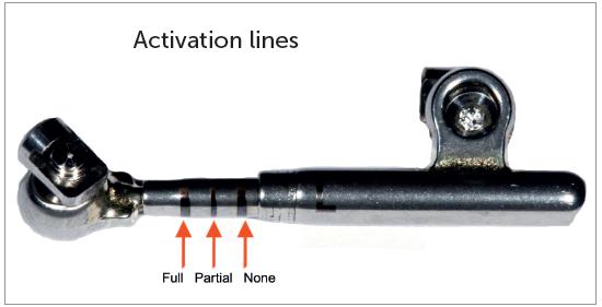
Figure 32
Activation indicator. Should three marks appear, this means the spring is not activated. Should two marks appear, this means the spring is partially activated. Should no marks appear, the appliance is totally activated.
Figure 33
Use of spacers in mandibular push rod: A) No spacer; B) After placement of six 1-mm spacers.
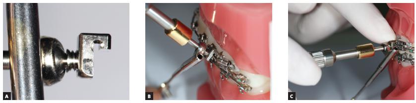
Figure 34
Step-by step placement: A) Initially, screw end should be leveled with the internal stop surface; B) Subsequently, the attachment nut is tipped in 45° relative to the arch; C) The nut should be pressed gently with clinician’s index finger, so as to fit the attachment nut into the arch and allow the appliance to remain parallel the occlusal plane. Thereafter, key should be turned with clinician’s right hand in short turns. Placement should be performed first in the maxilla and then in the mandible.
Figure 35
Appliance placement outside the mouth. Note the arch inside the attachment nut.
Figure 36
Mirror used to check whether the screw is completely closing the nut slot, thus preventing the attachment nut from falling loose.
Figure 37
Stop placement on the mesial surface of maxillary second molar tube.
Figure 38
Elastomeric ligature (With Guard, 3M Unitek, Monrovia, CA, USA) placement on distal wing of mandibular first premolar bracket. A rotation edge can also be used.
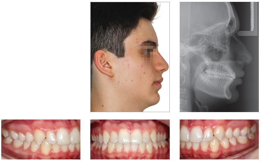
Figure 39
Pretreatment records: Extra and intraoral photographs, and lateral cephalogram.
Figure 40
Intraoral left photograph showing PowerScope appliance placement.
Figure 41
Intraoral left photograph showing fixed appliance at treatment completion.
Figure 42
Posttreatment records: Extra and intraoral photographs, and lateral cephalogram.
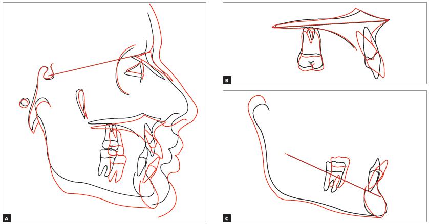
Figure 43
A) Cephalometric tracings superimposition on the cranial base (black = initial; red = treatment completion). B) Maxillary superimposition (ANS-PNS registered at ANS). C) Mandibular superimposition (Xi-Pm registered at Pm).
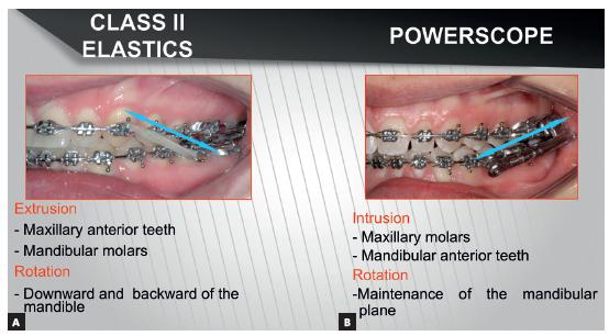
Figure 44
Direction of force for Class II correction: A) Class II elastics with traction force; B) Fixed functional appliance with impulsion force.
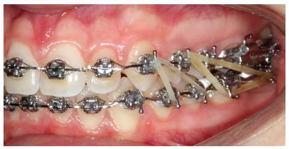
Figure 45
Class II compensatory treatment with PowerScope 2 in adult patient not willing to undergo orthognathic surgery.