Abstracts
The Diffuser Augmented Wind Turbines (DAWTs) have been widely studied, since the diffusers improve the power coefficient of the wind turbine, particularly of small systems. The diffuser is a device which has the function of causing an increase on the flow velocity through the wind rotor plane due to pressure drop downstream, therefore resulting in an increase of the rotor power coefficient. This technology aids the turbine to exceed the Betz limit, which states that the maximum kinetic energy extracted from the flow is 59.26%. Thus, the present study proposes a mathematical model describing the behavior of the internal velocity for three conical diffusers, taking into account the characteristics of flow around them. The proposed model is based on the Biot-Savart's Law, in which the vortex filament induces a velocity field at an arbitrary point on the axis of symmetry of the diffusers. The results are compared with experimental data obtained for the three diffusers, and present good agreement.
DAWTs; diffusers; wind energy; Biot-Savart's law
Difusores de aumento da potência de turbinas eólicas (DAWTs) têm sido amplamente estudados, uma vez que os difusores melhoraram o coeficiente de potência de turbinas eólicas, particularmente dos sistemas de pequeno porte. O difusor é um dispositivo que tem a função de provocar um aumento da velocidade do vento que passa através do plano do rotor eólico, devido a queda de pressão a jusante do difusor, por conseguinte, resultando em um aumento do coeficiente de potência do rotor. Esta tecnologia faz com que a turbina exceda o limite de Betz, onde a energia cinética máxima extraída do fluxo é de 59,26%. Assim, o presente estudo propõe um modelo matemático que descreva o comportamento do perfil de velocidade interna a três difusores cônicos, considerando as características do escoamento em torno deles. O modelo proposto baseia-se na lei de Biot-Savart, em que o filamento de vórtice induz um campo de velocidade num ponto arbitrário nos eixos de simetria dos difusores. Os resultados são comparados com dados experimentais obtidos para os três difusores, apresentando boa concordância.
DAWTs; difusores; energia eólica; lei de Biot-Savart
INTRODUCTION
The use of the diffusers on the horizontal-axis wind turbines aims at increasing the mass flow through the wind rotor. This effect increases the available rotor power, which in turn extracts more kinetic energy from the flow, when compared to a bare turbine (without diffuser). In recent years, the diffuser technology has been studied by many researchers around the world because of the improvement that the diffuser is capable of producing in wind turbines, particularly for small systems (Igra 1981IGRA O. 1981. Research and development for shrouded wind turbines. Energ Convers Manage 21: 13-48., Chen et al. 2012CHEN TY, LIAO YT AND Cheng CC. 2012. Development of small wind turbines for moving vehicles: Effects of flanged diffusers on rotor performance. Exp Therm Fluid Sci 42:136-142., Kishore et al. 2013KISHORE RA, COUDRON T AND PRIYA S. 2013. Small-scale wind energy portable turbine (SWEPT). J Wind Eng Ind Aerodyn: 116: 21-31.). Ohya and Karasudani (2010)OHYA Y AND KARASUDANI TA. 2010. Shrouded Wind turbine generating high output Power with wind-lens technology. Energies 3: 634-649. showed that the enhancement caused by the diffuser improves the rotor power coefficient by four to five times more of that of a bare wind turbine. A diffuser is a device that induces a pressure drop in the exit region (suction region downstream of the diffuser), and accelerates the fluid particles through the diffuser, increasing the flow velocity near the inlet (Bussel 1999BUSSEL GJWV. 1999. An Assessment of the Performance of Diffuser Augmented Wind Turbines (DAWT's). 3rd ASME/JSME Joint Fluids Engineering Conference, 1999, July 18-23, San Francisco, California, USA.). The diffuser induces an additional mass flow to the turbine, and the turbine power is proportional to the third power of the flow velocity through the rotor plane, but not to the third power of the free stream velocity. In fact, in this case, as analyzed by Jamieson (2011)JAMIESON P. 2011. Innovation in Wind Turbine Design. 1st ed., J Wiley & Sons., the upstream source area is k times greater than the rotor swept area, where k is the speed-up factor which increases the local air velocity at the rotor plane. Thus, it then clear that the energy extracted from the free wind velocity is no more than ktimes the energy produced by a bare turbine, at same conditions, andk3 times of what can be extracted from the streamtube. Oman et al. (1975)OMAN RA, FOREMAN KM AND GILBERT BL. 1975. A Progress Report on the Diffuser Augmented Wind Turbine, Proc. 3rd Biennal Conference and Workshop on Wind Energy Conversion Systems, Washington, D.C., USA, p. 819-826., Foreman and Gilbert (1979)FOREMAN KM AND GILBERT BL. 1979. Technical Development of the Diffuser Augmented Wind Turbine (DAWT) Concept, Wind Energy Innovative Systems Conf. Proc., Colorado Springs, Colorado, USA, p. 121-134. showed that the increasing of the diffuser velocity speed-up ratio (ratio between the maximum velocity in the diffuser and the undisturbed free-stream flow velocity) can be of two or more times, resulting in a proportional increase in the power coefficient, exceeding the Betz limit (1926)BETZ A. 1926. Wind-Energie und ihre Ausnutzung durch Windmuehlen. Vandenhoek, und Ruprecht, Gottingen. Reprint 1982, by Öko-Verlag Kassel, Germany . which is 59.26% in the case of the turbines without diffuser. Hansen et al. (2000)HANSEN MOL, SORENSEN NN AND FLAY RGJ. 2000. Effect of placing a diffuser around a wind turbine. Wind Energy 3: 207-213. conducted a study on diffuser augmented turbines using Computational Fluid Dynamic (CFD), where the increase of the velocity in the rotor plane was 1.83 for a case in which the cross section of the diffuser was the deformed NACA 0015 airfoil. These aspects highlight the importance of the development of models capable of accurately designing DAWTs. The main limitation of the diffuser augmented horizontal-axis wind turbines design, is that there is no formulation able to satisfactorily describe the diffuser geometry influence on the internal velocity profile. For overcoming this limitation, the present study shows a mathematical model which describes the internal velocity profile of a conical diffuser, using the Biot-Savart's Law (Kart and Plotkin 2001, Van Beveren 2008VAN BEVEREN SC. 2008. Design of an urban wind turbine with diffuser. Master thesis, Delft University of Tehnology, Delft, Netherland. (Unpublished).) to calculate the velocity induced by a vortex ring. As a complement, the results are compared with experimental data obtained for three different diffusers, and this reveals good agreement.
MATHEMATICAL MODEL
The velocity field in the conical diffuser is a combination of uniform and induced flows. The uniform part is defined as the undisturbed free-stream flow that arrives to the diffuser. The induced part is the influence provided by vortex ring. In this work a mathematical model for the induced velocity is presented, which depends on the diffuser geometry. Figure 1 shows two vortex rings using Biot-Savart's Law (Kart and Plotkin 2001, Van Beveren 2008) in cylindrical coordinates, where it is necessary to define the vortex element and position vector in relation to the axis of symmetry.
The Biot-Savart's Law is defined by:
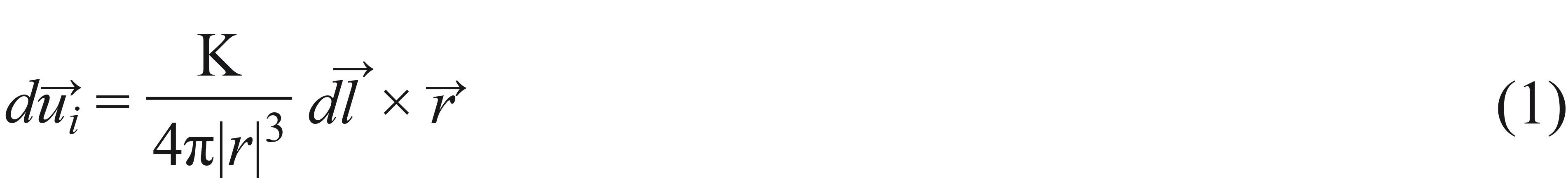
where  is the position vector and K is the circulation. The mathematical model considers the following assumptions: conical diffuser; the suction at the outlet of the diffuser is modeled using a vortex ring; the lock due to the presence of the diffuser on the flow is modeled as a steady inverted vortex ring and unidirectional. The inner vortex ring is responsible for increasing the flow velocity along the diffuser, and the frontal vortex ring predicts the reduction of the flow velocity near the inlet of the diffuser for high opening angle.
  is an elemental length of the vortex ring,
  is the induced velocity field,
The total velocity induced by the two vortex rings is the sum of the individual velocities  and
and , then:

Applying Eq. (1) in Eq. (2):

After some mathematical algebraic, and taking only the velocity in the direction of the longitudinal axis of the diffuser, the velocity induced by the vortex rings is (Barbosa et al. 2013BARBOSA DLM, VAZ JRP, RIO VAZ DATD, FIGUEIREDO SWO, SILVA MOS, MESQUITA ALA AND BLANCO CJCA. 2013. Mathematical Model for the Velocity Profile Internally to a Conical Diffuser. J Energy Power Eng 7: 1472-1477.):
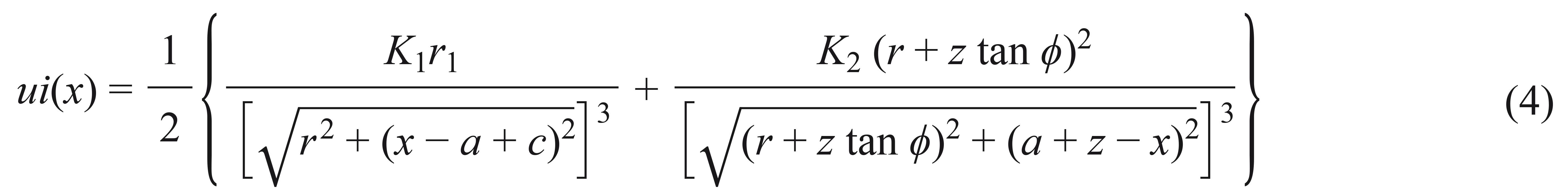
where R is the radius of the diffuser outlet, r is the radius of the diffuser inlet, a is the distance from the origin to the diffuser inlet, c and z are the distances from the vortex rings to the inlet part, and φ is the opening angle of the diffuser. For calculation of the circulations K1 and K2, the geometry of the diffuser, the behavior of the flow around the diffuser and the structure of the vortex formed in the inlet and outlet, are considered as shown in Figure 2.
For calculating the circulations K1 and K2, the following definitions are used:


where VT,1 = V0 sin φ and VT,2 = V0 cos φ are the tangential velocities of the elementary vortex, obtained from the freestream velocity decomposition. In this case, it is admitted that the elementary lengths, ds1 and ds2, depend of the elementary vortex radii, b1 and b2, as shown in Figure 2. Based on the structure of the vortex:
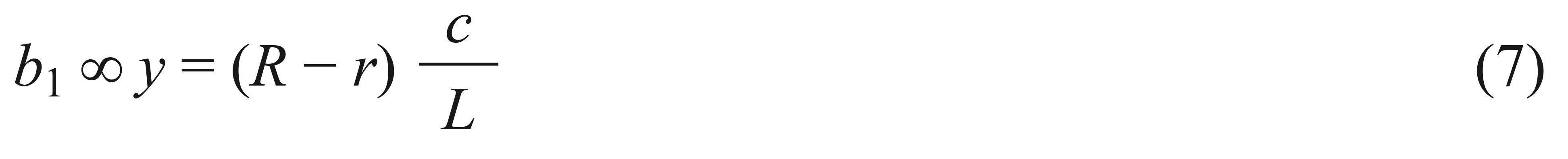

where y is obtained by similarity of triangles shown in Figure 2. Therefore, ds1 = b1dα1 and ds2 = b2dα2, and α1 and α2 are the elementary vortex angles. Equations (5) and (6) are reduced to:


where ξ1 and ξ2 are proportionality constants that act as correction factors. The minus signal in Eq. (9) means counterclockwise due to the reverse direction of the frontal vortex ring.
Van Beveren (2008) shows that the internal velocity profile of a diffuser is given by the sum of the velocity induced by the ring vortex and the undisturbed flow velocity:

The ratio of the effective velocity u(x) to the freestream velocity V0 is called diffuser velocity speed-up ratio, and is denoted by:
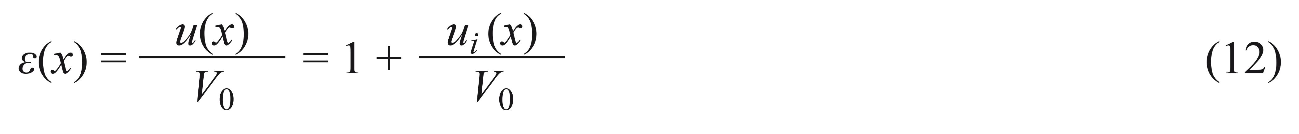
The parameters c, z, ξ1 and ξ2 are obtained empirically based on experimental data, as will be seen later.
EXPERIMENTAL MEASUREMENTS
The model validation was done using data acquired from experimental measurements on velocity and dynamic pressure of three different 0.5mm thick conical diffusers shown in Figure 3.
The geometric configurations of the diffusers were chosen to evaluate the behavior of the axial velocity along the diffuser for different opening angles and different lengths. Matsushima et al. (2006)MATSUSHIMA T, TAKAGI S AND MUROYAMA S. 2006. Characteristics of a highly efficient propeller type small wind turbine with a diffuser. Renewable Energy 31: 1343-1354. showed that the diffuser velocity speed-up ratio increases more steeply for angles less than 4º reaching and reaches the maximum when opening angle is 6º. For angles wider than 6º, the speed-up ration begins to decrease. The dimensions of the three diffusers are shown in Figure 4, and were used in the mathematical model.
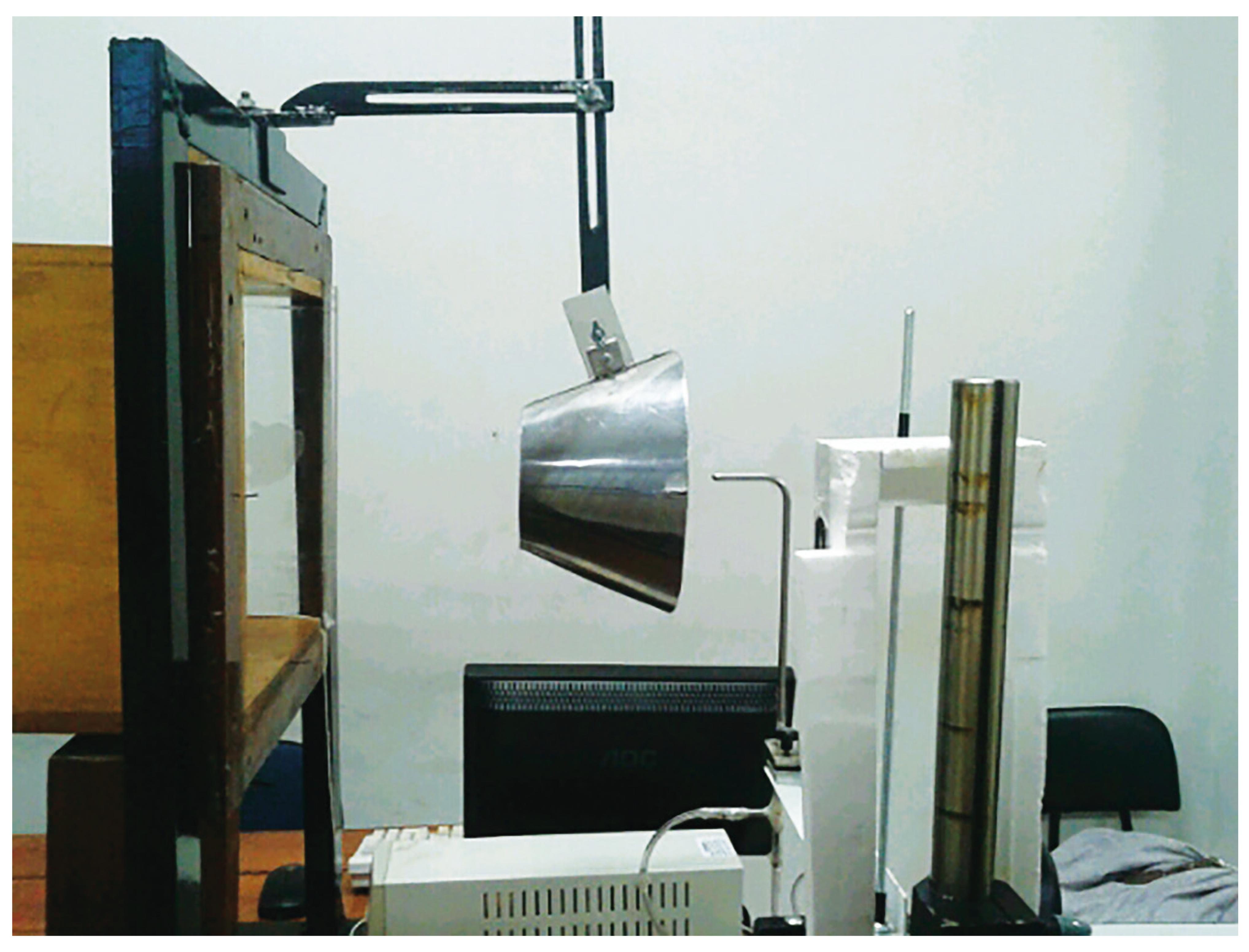
The experiment was conducted in a wind tunnel (controlled by frequency inverter) operating at three different rotations, 400, 600 and 800rpm, corresponding to speeds 4.05, 6.65 and 9.05m/s, respectively. The purpose of using the three speeds was to evaluate if diffuser velocity speed-up ratio depends only on its geometry. Measurements of dynamic pressures were performed using a type L Pitot probe of 7.0mm diameter and 300mm length. The apparatus also comprised a digital micro-manometer, a linear positioner and a microcomputer. The displacement of the Pitot tube on the linear positioner was controlled by the microcomputer. The option for Pitot probe occurred due to the initial purpose of determining the velocity distribution along the axis only, leaving aside the quantification and characterization of the vortices generated; otherwise laser Doppler anemometry (LDA) or particle image velocimetry (PIV) could be applied, as commonly used in turbulent flows (Hoopen 2009HOOPEN PDC. 2009. An Experimental and Computational Investigation of a Diffuser Augmented Wind Turbine: with an application of vortex generators on the diffuser trailing edge, M.Sc. Thesis, Faculty of Aerospace Engineering, Delft University of Technology. (Unpublished)., Hu et al. 2012HU H, YANG Z AND SARKAR P. 2012. Dynamic wind loads and wake characteristics of a wind turbine model in an atmospheric boundary layer wind. Experiments in Fluids 52: 1277-1294.). The velocity distribution along the axis for a given diffuser is a function only of space and geometric dimensions. So, for any values of speed imposed to the diffuser, the velocity speed-up ratio curve has the same shape, as will be shown after. The measurements were performed with the diffuser positioned right in front of the tunnel exit, under the action of air jet. This configuration was chosen due to the fact that the cross section of the wind tunnel (310mm x 310mm) was insufficient to hold the body of the Diffuser 1 (outlet diameter D = 259mm), and it would induce wall effects on the flow surrounding the diffuser. Figure 5 illustrates the experimental apparatus.
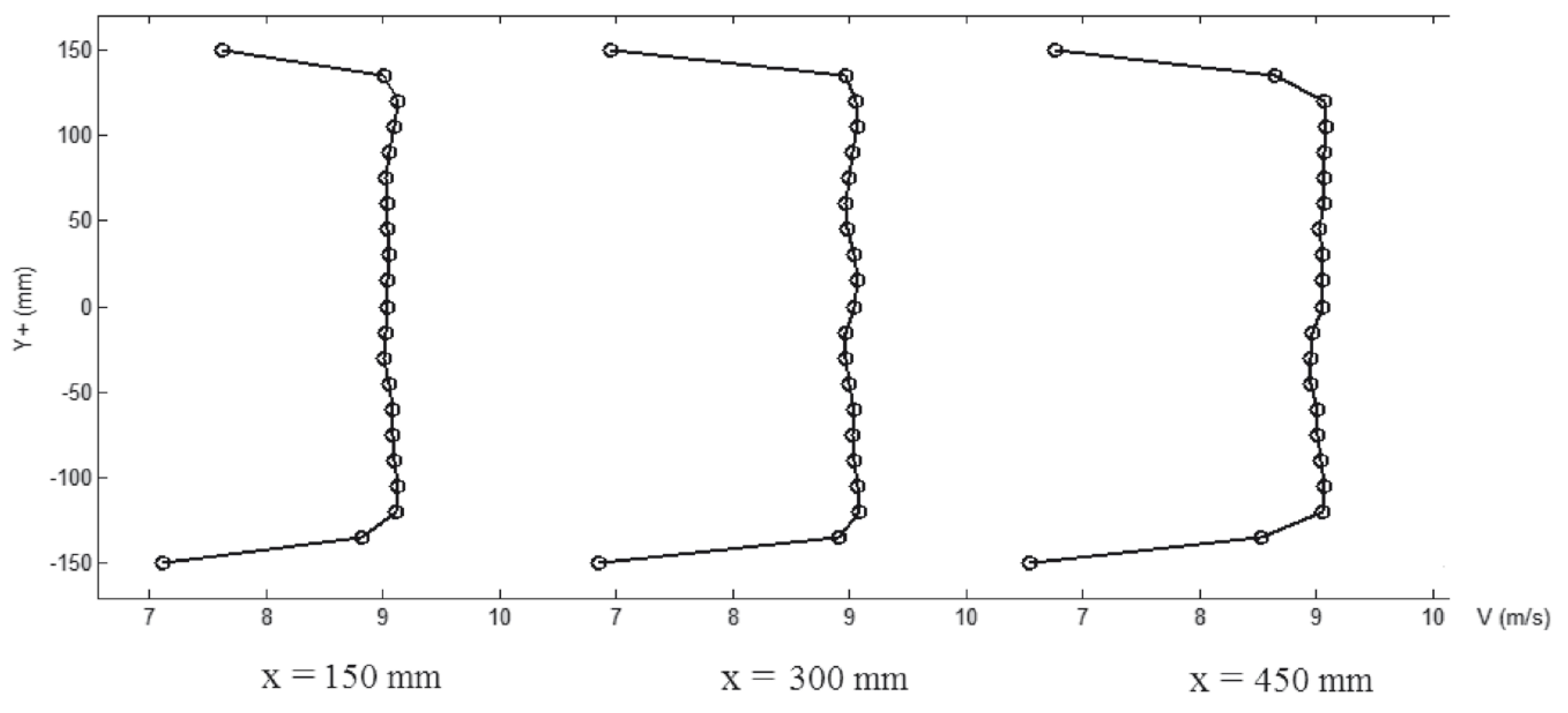
As the flow was similar to air jet, it was necessary to accomplish a mapping of the influence region of this jet (external to wind tunnel) to verify if the flow would maintain itself uniform as it moved away from the wind tunnel exit. So, three velocity profiles were measured from the wind tunnel exit, without the diffuser, with a spacing of 150mm between each profile, totaling a distance of 450mm. The choice of measurement up to the point 450 mm away from the exit of the wind tunnel was made so that the diffuser of greater length, Diffuser 2 (L = 255mm) would be covered by the region of the flow. In each profile, measurements on the vertical direction (Y +) were equally spaced in 15mm, assuming the origin of the Y + axis to be located in the center of the tunnel (Fig. 6).
The velocity distributions at the positions 150, 300 and 450mm are shown below:
These results, in Figure 7, indicate that the speeds measured at positions equidistant from the wind tunnel are very close; this means profile remains almost constant 450mm far from the wind tunnel exit. The results also indicate almost no vertical velocity gradient on the region betweenY + = − 120mm and Y + = 120mm, then the flow configuration is satisfactory for the purpose of this work.
Based on the verification that the air flow outside of the wind tunnel was uniform until 450mm, the experiments were done on diffusers positioned 250mm far from the exit of the wind tunnel. An example of the velocity measurements with Diffuser 3 is shown in Figure 8 with the Pitot probe installed on the positioner.
RESULTS AND DISCUSSIONS
EXPERIMENTAL RESULTS
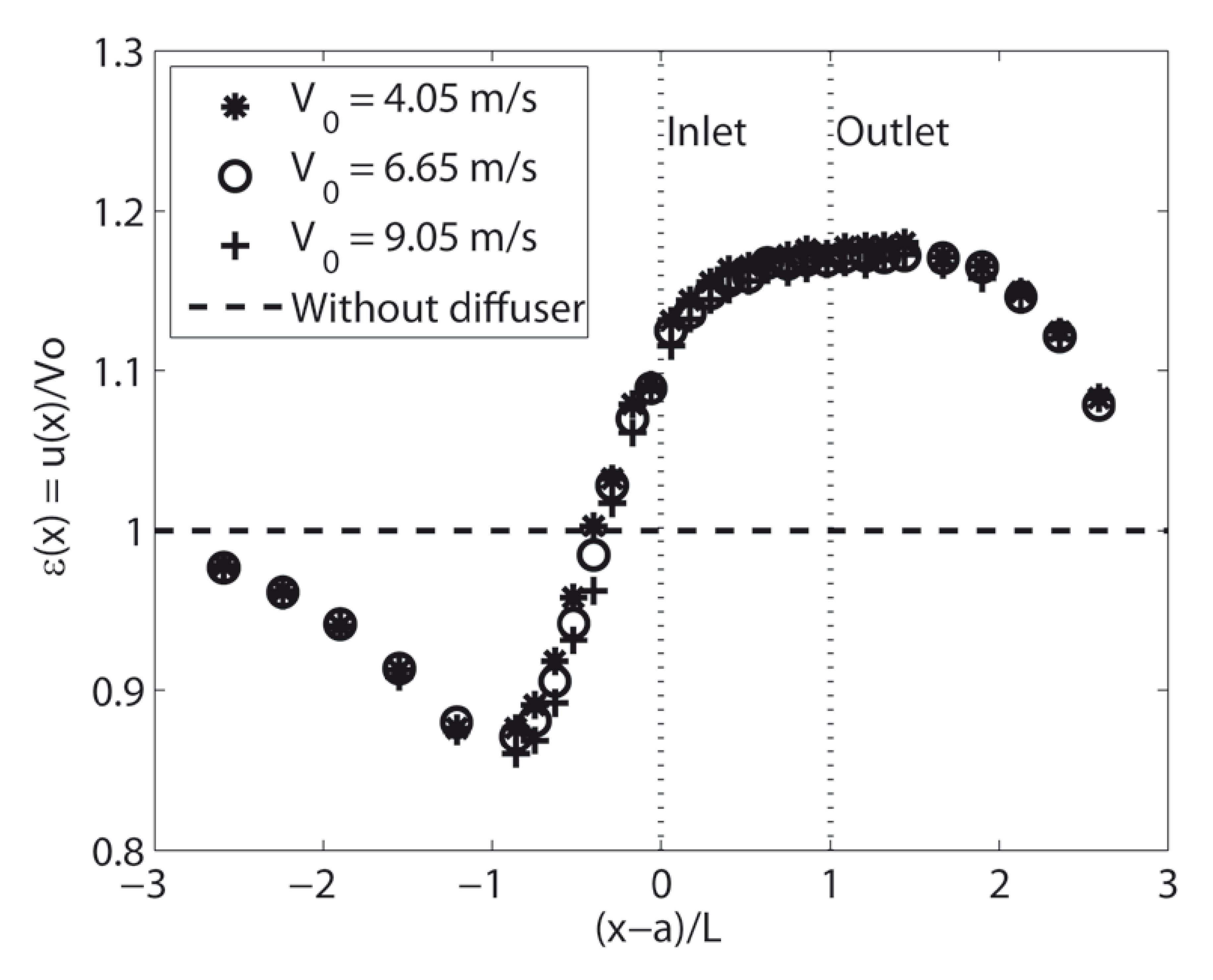
The velocity values for each point along the longitudinal axis of the diffusers were obtained from a sample of 500 measurements. The results present uncertainty of 0.04m/s at 95% of confidence level, which enables adequate repeatability. The x-axis is normalized by using (x − a) /L, thereby the inlet of the diffuser is at point 0 and its outlet at point 1 for the three geometries. In addition, the diffuser`s inlet and outlet are delimited by dotted lines (Inlet and Outlet). In all Figures of this section, the statement "Without diffuser" means that the velocity profile becomes constant with a value equal to the freestream velocity, once there is not the influence of the diffuser. Figures 9, 10 and11 show the diffuser velocity speed-up ratios for the geometries 1, 2 and 3, respectively. For each diffuser, it is confirmed that the curves of the velocity speed-up ratio depend only on the geometry. This result is very important, showing that the mathematical models based on the Biot-Savart's Law (Katz and Plokin 2001KATZ J AND PLOTKIN A. 2001. Low Speed Aerodynamics, CUP, 2nd ed., Cambridge University Press, p. 611., Van Beveren 2008) are indicated for the determination ofε (x), since Biot-Savart's Law is a function only of the diffuser geometry. Note that the velocity increases between inlet and outlet for the Diffusers 1 and 3; and, for the Diffuser 2, increases at the inlet. The increased velocity is due to the flow separation near the wall, which creates a sub-atmospheric region at the outlet of the diffuser. Jafari and Kosasih (2014)JAFARI SAH AND KOSASIH B. 2014. Flow analysis of shrouded small wind turbine with a simple frustum diffuser with computational fluid dynamics simulations. J Wind Eng Ind Aerodyn 125: 102-110. developed an experimental and computational fluid dynamic study, where a significant power augmentation of a shrouded conical diffuser of a horizontal axis wind turbine was demonstrated. These studies found that the degree of the augmentation is strongly dependent on the shape and geometry of the diffuser such as the length and the expansion angle. According to Jafari and Kosasih (2014), the flow separation is significantly affected by the diffuser area ratio between inlet and outlet, which is responsible for variation of the velocity internally to diffusers. Ohya and Karasudani (2010) showed that if a long type diffuser is used, the air speed is accelerated further near the inlet of the diffuser. This effect occurs in the Diffuser 2 shown in Figure 10. However, a long and heavy structure is not preferable in the practical sense. This velocity increasing effect has enabled the development of new technologies, which benefit from the modification of the diffusers geometries that have been widely studied in the last years (Ohya and Karasudani 2010, Abe and Ohya 2004ABE K AND OHYA Y. 2004. An Investigation of Flow Fields Around Flanged Diffusers Using CFD. J Wind Eng Ind Aerodyn 92: 315-330.), in order to improve the wind turbine design, in more economic manner.
Figure 12 shows, simultaneously, the velocity speed-up ratios for the three geometries. In this graph, it is noted that the opening angle is responsible for reduction of the velocity speed-up ratios, and the region of maximum velocity heads toward the outlet of the diffuser, for the cases 1 and 3. For Diffuser 2, the maximum velocity occurs at the inlet. A reduction also occurs in wind speed before it approaches the diffuser inlet, which is a result of the blocking effect caused by the diffuser on the flow due to the increase of the projected area on the perpendicular plane to the diffuser axis of symmetry. Another important result is the variation of the opening angle, because the velocity speed-up ratio can move inside of the diffuser, and for a higher angles, the maximum value position of ε (x) approximates the outlet.
RESULTS OF THE PROPOSED MODEL COMPARED WITH THE EXPERIMENTAL DATA
In order to evaluate the behavior of the proposed model, it is necessary to determine the parameters c, z, ξ1 andξ2 which are obtained through the experimental data presented in the previous sub-section. Using the comparison between theoretical and experimental data, it was observed that the parameter c becomes the same value for the three diffusers, so, its value is:

This result for c indicates that the frontal vortex ring has fix localization upstream the diffuser. The computational problem was resolved with assistance of Matlab routines that use comparison method (Chapman 2010CHAPMAN SJ. 2010. Programação em MATLAB para Engenheiros, 2a ed., São Paulo, Cengage Learning.). With this approach, the rule is a curve where the mathematical model reaches the maximum value of the experimental curve, because the wind turbine must be placed at this position. For the parametersz, ξ1 and ξ2, a relation was observed with the aspect ratio L / D; therefore, by using quadratic interpolation for these values, the expressions forz, ξ1 and ξ2 can be empirically determined:
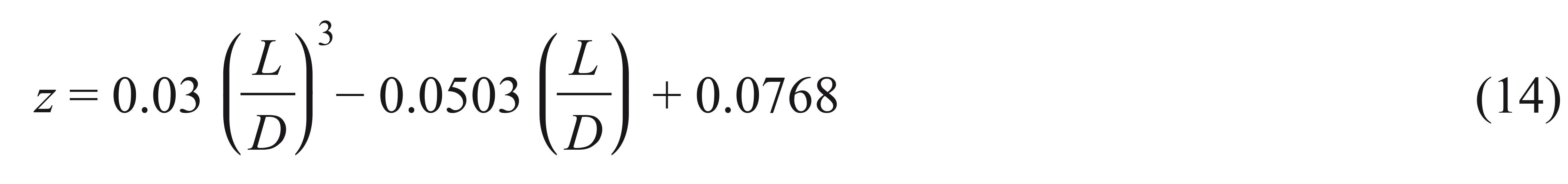

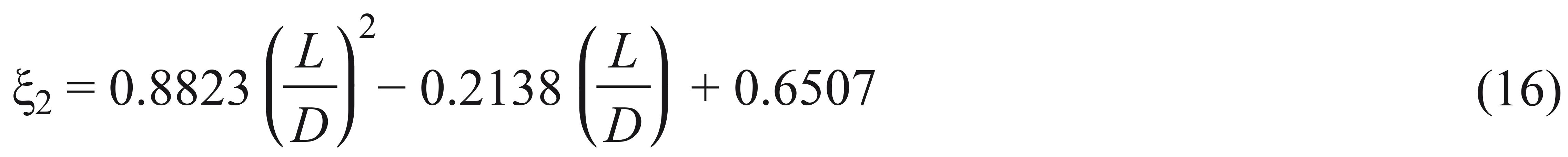
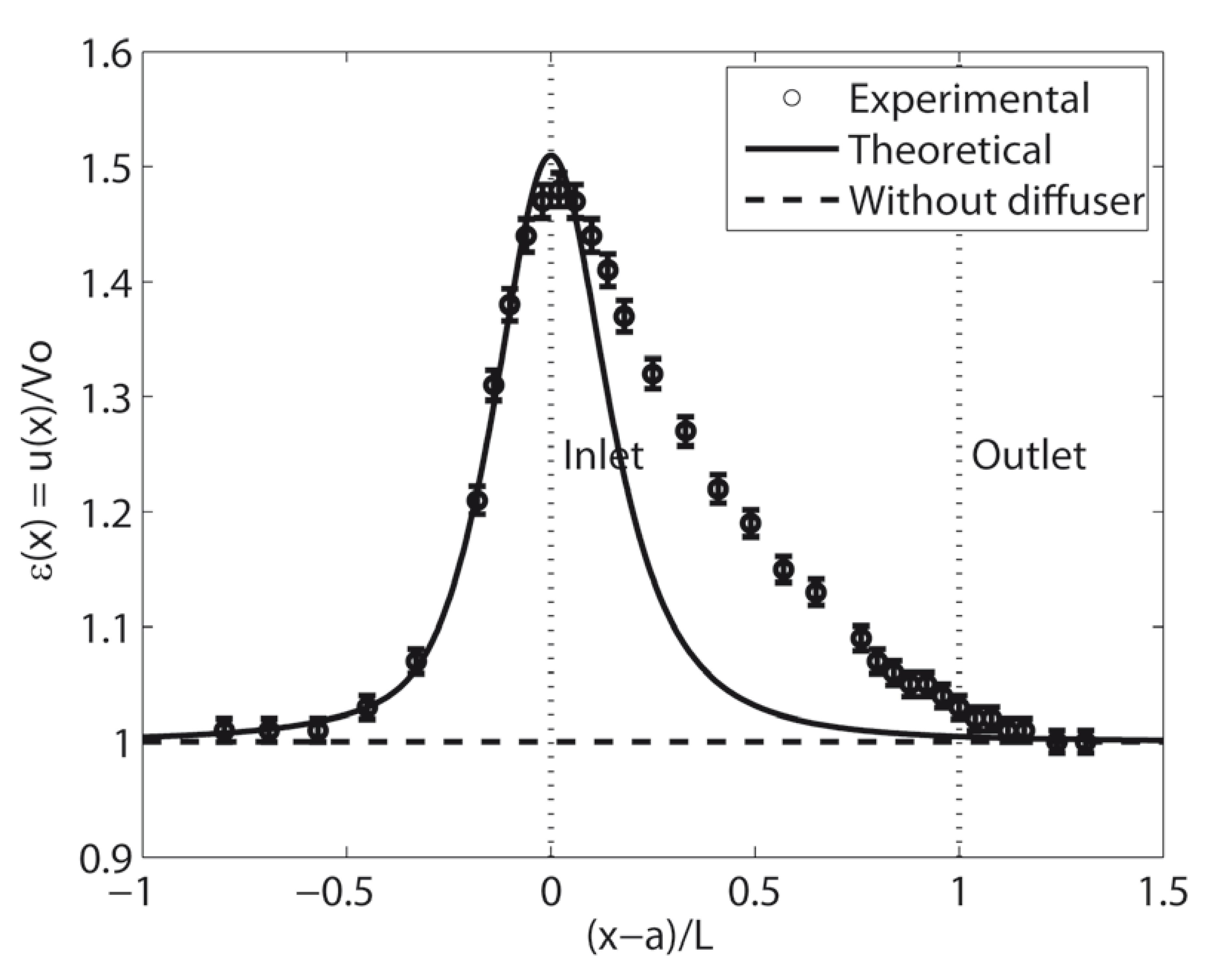
Finally, by using Eqs. (4), (13), (14), (15) and (16), the mathematical model can be implemented for any conical diffuser, since these values depend only on the geometry. Figures 13, 14 and 15 show the velocity speed-up ratio calculated by Eq.(12) compared with experimental data obtained in this work.
For Diffuser 1, the velocity speed-up ratio at upstream (undisturbed flow region) differs from the proposed model, due to the blocking effect, because the opening angle is 40º. From the minimum to the maximum point of the velocity speed-up ratio, the results show good agreement with experimental data, diverging from the maximum point up to diffuser downstream . This occurs due to the limitation of the theoretical model which considers only one vortex ring moving inside the diffuser. Hoopen (2009) demonstrates that it is possible to use Gibson's solution for elliptical integrals applied to the whole diffuser. In other words, for integrating a set of vortex rings along the axis of symmetry of the diffuser; however, more investigation is required. For the Diffuser 2, there was no reduction on the velocity upstream due to projected area to be minimum. This comparative result indicates that the mathematical model has limitations, but inside the diffuser region it presents a good behavior.
In the case of Diffuser 2, shown in Figure 14, for small expansion angle (5º), the vortex strength is very weak, since the model is represented by only one vortex ring, promoting the discrepancy on the velocity comparison inside of diffuser.
Comparing the results obtained in this work with those obtained by Abe and Ohya (2004), there is a difference in the velocity profile along the axis. The flows on the Diffusers 1 and 3 tested here show reduction in speed before reaching the inlet, and differ from the comparative case (proposed mathematical model) and from the Diffuser 2 which shows acceleration of the flow from the upstream velocity at the diffuser inlet, followed by a deceleration, again reaching the freestream velocity at the outlet. This difference is probably caused by the opening angles of the Diffusers 1 and 3 tested (φ = 22.5º and φ = 40º), which causes blocking effect on the flow. It should be noted that the optimal value for this angle is adopted as φ = 4º (Chapman 2010). In a diffuser, the flow expands along its inner wall, resulting in decreased speed and consequently an increase in pressure coefficient toward the diffuser outlet (Abe and Ohya 2004) called adverse pressure gradient. Based on this, even with a large opening angle, the velocity profile of the diffuser entry is similar to those diffusers which haveL / D reduced, or increased followed by speed reduction.
Ohya and Karasudani (2010) indicated that for a diffuser with opening angleφ = 4º, the maximum velocity speed-up ratio is located inside the diffuser and near its inlet (see Fig.16).
Based on the study performed in this work, the opening angle φ = 5º for the Diffuser 2 reached the same results, that is, the maximum velocity point occurring for small angles and near the inlet. Therefore, it would be more convenient to install the turbine in the region where the velocity is maximum. However, Figure 17 shows that for bigger angles, the flow can be turbulent, and the turbine would lose the lift necessary for the extraction of the available wind energy, and consequently, there would be power coefficient decrease. It is necessary to conduct experimental measurements for other diffuser`s geometries to evaluate the parameters c andz, and refine the mathematical model.
Therefore, the ideal position for installing a turbine is near the diffuser inlet, because in this region the stream lines are uniform (laminar flow), and it avoids the turbulent flow caused by boundary layer separation on the inner wall and belt region, taking advantage of the speed gains without compromising the increased efficiency of the turbine.
DIFFUSER EFFECT ON AN IDEAL WIND TURBINE - DAWT
For evaluating the results obtained in this work on the theoretical power coefficient of a DAWT, the model proposed by Rio Vaz et al. (2014)RIO VAZ DATD, BLANCO CJC, MESQUITA ALA, VAZ JRP AND PINHO JT. 2014. An Extension of the BEM Method Applied to DAWTs. Energ Convers Manage 87:1116-1123. http://dx.doi.org/10.1016/j.enconman.2014.03.06.
http://dx.doi.org/10.1016/j.enconman.201...
will be used, which is given by Eq. (17).

where max = εmax[(ε(x))] is the maximum diffuser velocity speed-up ratio, and it corresponds to the position where the turbine must be installed in the diffuser. The axial induction factor ã at the rotor plane can be written as a function of the thrust coefficient CT, such as:
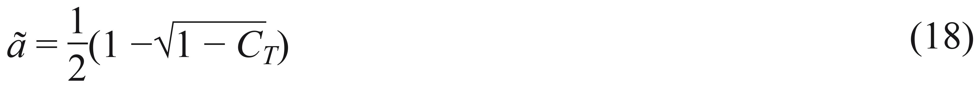
Table I shows the maximum power coefficient obtained for an ideal wind turbine using the proposed model. Note that the maximum diffuser velocity speed-up ratio is the maximization of Eq. (12).
Figure 18 shows the diffuser effect on the power coefficient of the wind turbine. It is observed that the diffuser improves efficiency, as shown in Phillips (2003)PHILLIPS DG. 2003. An Investigation on Diffuser Augmented wind Turbine Design. Department of Mechanical Engineering School of Engineering. The University of Auckland, Doctoral thesis. Auckland.. In this case, better results were obtained for Diffuser 2, which provided 89.32% of maximum extracted energy, and, as a consequence, exceeded the Betz's limit.
Another important result is shown in Figure 19, where the diffuser effect on the induced velocity at the actuator disc is presented. The result was obtained considering an ideal turbine (ã = 1/3), with V0 = 1.0 m/s, and a cubic interpolation betweenV0, u = εmax (1−ã)V0, and u1 =εmax (1−2ã)V0 was done for the calculation of velocity profile flow. In this case, it is observed that the increase of the diffuser velocity speed-up ratio modifies the induced velocity at the turbine. This fact, shows that the flow velocity in the wind rotor plane is not the sum divided by two of the wind speed u1 and the velocity in the wake u1, for the classical theory case (without the diffuser). This effect is noted for εmax = 1.5098, resulting in u1 = 1.0064V0, and u1 = 0.33V0. Thus, considering that there are no losses through the diffuser, the maximum energy extracted by a DAWT is CP max = εmax1627.
In this work the power coefficient was considered for an ideal diffuser augmented wind turbine, where the effect of the insertion of the turbine blades into the diffuser is not computed. For a first design evaluation the proposed methodology gives good information on the diffuser effect. More details on the diffuser effect for wind turbine design can be obtained in Rio Vaz et al. 2014, Fletcher 1980FLETCHER CAJ. 1980. Diffuser-augmented wind turbine analysis. 7th Australasian Hydraulics and Fluid Mechanics Conference, Brisbane, p. 18-22., Dick 1984DICK E. 1984. Momentum analysis of wind energy concentrator systems. Energ Convers Manage 24:19-25..
CONCLUSIONS
The velocity distribution obtained with the proposed model adequately matches the experimental data inside the diffuser region up to the maximum velocity value, where the velocity gradient is positive. After this maximum value, the velocity gradient is negative and the theoretical results are in discrepancy with the experimental data, due to the viscous effects and separation flow, in particular for high opening angles of the diffuser, as already discussed. It is important to note, that the proposed model is based on the Biot-Svart's Law, which is obtained from classical potential theory, as described in Katz and Plotkin 2001. Thus, the present approach does not take into account the viscous effect, which is predominant for high angles. Even if results are presented for high opening angles, the methodology is more adequate for small angles, as is the case for DAWT's applications. For small opening angles, like the Diffuser 2 (5º) the proposed methodology gives good results for engineering design purpose. It is intended that the elevated velocities occurs inside the diffuser, especially at the laminar region of the flow. The experimental data is important because it indicates the best position for placing a wind turbine. The blocking effect on the flow lowers the velocity profile near the diffuser inlet, specially for wide opening angles. Therefore, it is necessary, in principle, to use small opening angles (φ = 4º) in order to reduce the blockage effect on the flow at the diffuser entry region for preventing the increase of pressure and the consequent speed reduction. It will be seen ahead that such condition is of extreme importance for placing turbines in the diffuser inlet region.
In the design of wind turbines with diffusers, analytical models, as proposed in this work, are important because these can be coupled to existing classical models, such as Glauert (1947)GLAUERT H. 1947. The Elements of Aerofoil and Airscrew Theory, CUP, 2nd ed., p. 232. and Rio Vaz et al. (2013) in order to supplement or improve them. Experimental data for other configurations of conical diffusers are currently being obtained to better evaluate and refine the mathematical model proposed. It was also observed that the ratio of length to diffuser outlet diameter (length ratio) is closely related to the location of a maximum velocity speed-up ratio. Thus, the proposed model has limitations, such as not taking into account the variation of the velocity for each cross section of the diffuser. It can be inferred that, for small expansion angles, the velocity at inlet is maximum and could be almost uniform. However, for the large expansion angle case, the separation is expected within the diffuser, which indicates that the velocity might not be uniform. Thus, more investigations about this matter are necessary. For example, Rio Vaz et al. (2014) developed an extension of the blade element momentum method applied to DAWT, and showed that the diffuser velocity speed-up ratio is a function of the radial position for a flow assumed as axisymmetric. In this work the velocity variation along the radius of the diffuser is similar to that obtained along the longitudinal axis. The results presented are important principally for regions not affected by the flow separation. In these cases, the results can be significant and applicable to DAWTs project aiming at the enhancement of the extraction of wind energy, resulting in increased efficiency.
ACKNOWLEDGMENTS
The authors would like to thank UFPA, Conselho Nacional de Desenvolvimento Científico e Tecnológico (CNPq), Coordenação de Aperfeiçoamento de Pessoal de Nível Superior (CAPES), INCT - EREEA and ELETRONORTE for financial support.
REFERENCES
- ABE K AND OHYA Y. 2004. An Investigation of Flow Fields Around Flanged Diffusers Using CFD. J Wind Eng Ind Aerodyn 92: 315-330.
- BARBOSA DLM, VAZ JRP, RIO VAZ DATD, FIGUEIREDO SWO, SILVA MOS, MESQUITA ALA AND BLANCO CJCA. 2013. Mathematical Model for the Velocity Profile Internally to a Conical Diffuser. J Energy Power Eng 7: 1472-1477.
- BETZ A. 1926. Wind-Energie und ihre Ausnutzung durch Windmuehlen. Vandenhoek, und Ruprecht, Gottingen. Reprint 1982, by Öko-Verlag Kassel, Germany .
- BUSSEL GJWV. 1999. An Assessment of the Performance of Diffuser Augmented Wind Turbines (DAWT's). 3rd ASME/JSME Joint Fluids Engineering Conference, 1999, July 18-23, San Francisco, California, USA.
- CHAPMAN SJ. 2010. Programação em MATLAB para Engenheiros, 2a ed., São Paulo, Cengage Learning.
- CHEN TY, LIAO YT AND Cheng CC. 2012. Development of small wind turbines for moving vehicles: Effects of flanged diffusers on rotor performance. Exp Therm Fluid Sci 42:136-142.
- DICK E. 1984. Momentum analysis of wind energy concentrator systems. Energ Convers Manage 24:19-25.
- FLETCHER CAJ. 1980. Diffuser-augmented wind turbine analysis. 7th Australasian Hydraulics and Fluid Mechanics Conference, Brisbane, p. 18-22.
- FOREMAN KM AND GILBERT BL. 1979. Technical Development of the Diffuser Augmented Wind Turbine (DAWT) Concept, Wind Energy Innovative Systems Conf. Proc., Colorado Springs, Colorado, USA, p. 121-134.
- GLAUERT H. 1947. The Elements of Aerofoil and Airscrew Theory, CUP, 2nd ed., p. 232.
- HANSEN MOL, SORENSEN NN AND FLAY RGJ. 2000. Effect of placing a diffuser around a wind turbine. Wind Energy 3: 207-213.
- HOOPEN PDC. 2009. An Experimental and Computational Investigation of a Diffuser Augmented Wind Turbine: with an application of vortex generators on the diffuser trailing edge, M.Sc. Thesis, Faculty of Aerospace Engineering, Delft University of Technology. (Unpublished).
- HU H, YANG Z AND SARKAR P. 2012. Dynamic wind loads and wake characteristics of a wind turbine model in an atmospheric boundary layer wind. Experiments in Fluids 52: 1277-1294.
- IGRA O. 1981. Research and development for shrouded wind turbines. Energ Convers Manage 21: 13-48.
- JAFARI SAH AND KOSASIH B. 2014. Flow analysis of shrouded small wind turbine with a simple frustum diffuser with computational fluid dynamics simulations. J Wind Eng Ind Aerodyn 125: 102-110.
- JAMIESON P. 2011. Innovation in Wind Turbine Design. 1st ed., J Wiley & Sons.
- KATZ J AND PLOTKIN A. 2001. Low Speed Aerodynamics, CUP, 2nd ed., Cambridge University Press, p. 611.
- KISHORE RA, COUDRON T AND PRIYA S. 2013. Small-scale wind energy portable turbine (SWEPT). J Wind Eng Ind Aerodyn: 116: 21-31.
- MATSUSHIMA T, TAKAGI S AND MUROYAMA S. 2006. Characteristics of a highly efficient propeller type small wind turbine with a diffuser. Renewable Energy 31: 1343-1354.
- OHYA Y AND KARASUDANI TA. 2010. Shrouded Wind turbine generating high output Power with wind-lens technology. Energies 3: 634-649.
- OMAN RA, FOREMAN KM AND GILBERT BL. 1975. A Progress Report on the Diffuser Augmented Wind Turbine, Proc. 3rd Biennal Conference and Workshop on Wind Energy Conversion Systems, Washington, D.C., USA, p. 819-826.
- PHILLIPS DG. 2003. An Investigation on Diffuser Augmented wind Turbine Design. Department of Mechanical Engineering School of Engineering. The University of Auckland, Doctoral thesis. Auckland.
- RIO VAZ DATD, BLANCO CJC, MESQUITA ALA, VAZ JRP AND PINHO JT. 2014. An Extension of the BEM Method Applied to DAWTs. Energ Convers Manage 87:1116-1123. http://dx.doi.org/10.1016/j.enconman.2014.03.06.
» http://dx.doi.org/10.1016/j.enconman.2014.03.06 - RIO VAZ DATD, VAZ JRP, MESQUITA ALA, PINHO JT AND Brasil ACP. 2013. Optimum Aerodynamic Design for Wind Turbine Blade with a Rankine Vortex Wake. Renewable Energy 55: 296-304.
- VAN BEVEREN SC. 2008. Design of an urban wind turbine with diffuser. Master thesis, Delft University of Tehnology, Delft, Netherland. (Unpublished).
Publication Dates
-
Publication in this collection
28 Apr 2015 -
Date of issue
Apr-Jun 2015
History
-
Received
19 Mar 2014 -
Accepted
25 Nov 2014