
Abstract
The fuel element of LMFBR consists of a bundle of rods wrapped with an helical wire as spacer, surrounded by an hexagonal duct. In the present work, a semi-empirical model is developed to calculate bundle average and subchannel based friction factors and flow redistribution. The obtained results were compared to experimental data and they were considered satisfactory for wide range of geometrical parameters.
Flow redistribution; friction factors; turbulent mixing; nuclear reactor design; fast breeder reactors
Model for Subchannel Friction Factors and flow Redistribution IN Wire-Wrapped Rod Bundles
Pedro Carajilescov
Departamento de Engenharia Mecânica
Universidade Federal Fluminense, Niterói, RJ
Elói Fernandez y Fernandez
Departamento de Engenharia Mecânica
Pontifícia Universidade Católica do Rio de Janeiro
Abstract
The fuel element of LMFBR consists of a bundle of rods wrapped with an helical wire as spacer, surrounded by an hexagonal duct. In the present work, a semi-empirical model is developed to calculate bundle average and subchannel based friction factors and flow redistribution. The obtained results were compared to experimental data and they were considered satisfactory for wide range of geometrical parameters.
Keywords: Flow redistribution, friction factors, turbulent mixing, nuclear reactor design, fast breeder reactors.
Introduction
Currently, LMFBR (Liquid Metal Fast Breeder Reactors) fuel elements consist of wire-wrapped rod bundles, in a triangular array, with the fluid flowing along the rods. Figure 1 presents an schematic view of a typical 19-rod fuel element. The coolant flows upward through three different kinds of subchannels (interior, edge and corner subchannels), as shown in the figure.
a) Thermal conduction _ responsible for the molecular thermal diffusion in fluids with high thermal conductivity ;
b) Turbulent mixing _ thermal transport associated to the flow turbulent level;
c) Scattering flow _ forced non-directional mixing associated to the increased turbulent level induced by the wire-wrapped spacer. Usually, this effect is included directly in the turbulent mixing;
d) Crossflow _fluid convection induced by radial pressure gradient. In the present case, the crossflow can be divided in:
· Diversion flow _ associated to different local characteristics of subchannel, such as area variations, fluid properties and subchannel geometries.
· Sweep flow _ associated to the flow path created by the direction of the wire wrap, in the sense that, every time the wrap crosses the gap between two rods, the flow is directed, partially, from one subchannel to the other, due to the favorable pressure gradient created by the spacer.
· Swirl flow _ the sweep flow, in the edge and corner subchannel, has different characteristics when compared to the interior subchannel. While, in the interior subchannels, the sweep flow changes its direction periodically, the sweep flow near the duct wall is always in the same direction, generating the so-called swirl flow.
Due to the presence of the wire, the principal mechanism of transversal enthalpy mixing is the crossflow, which changes with the axial position.
Several computer codes, originally developed for water cooled reactors, were adapted for this type of geometry, in order to simulate the flow conditions. Very few codes were developed specifically for this type of reactor. As a general characteristic of these codes, the fuel element is divided in control volumes defined by each subchannel and an axial length, Dz. The conservation equations (mass, momentum and energy) are, then, written for each control volume and numerically solved. The major differences among the codes are related to the manner the several flow characteristics are treated and the imposed boundary conditions. All of these codes require, as input, correlations for the friction factors and some information about the flow redistribution among the different type of subchannels.
The present work presents a semi-empirical model to calculate the friction factors for the whole bundle as well as for each type of subchannel and provides means to obtain the flow redistribution parameters.
Formulation
As mentioned, correlations for friction factors represent an important input for thermalhydraulic analysis codes. Several authors have developed bundle average friction factors, as functions of the assembly geometry. Among them, it can be mentioned Novendstern (1972), Rehme (1973) and Engel et al. (1979). However, these authors did not extend their efforts to correlate subchannel based friction factors. For turbulent flow in interior and edge subchannels, Chiu et al. (1980) proposed a model considering pressure drop due to form drag of the wires and skin friction of the rods and wall. An extension of Chiu's method was proposed by Hawley et al. (1980), for laminar flows. For the transition region, Hawley superposes the laminar and turbulent friction factors. Similar approach was followed by Cheng and Todreas (1985). Nevertheless, the empirical or semi-empirical models proposed by those authors lead to correlations that are either complex or cannot be extended to large range of values of P/D and H/D, and different number of rods, N, with these parameters defined in Fig. 1. A good assessment of existing correlations can be found in Todreas and Kazimi (1993).
The semi-empirical model, proposed in this paper to calculate subchannels and bundle average friction factors, overcome these limitations and provides reliable information to the thermal analysis codes.
It is assumed that, along the flow path, the pressure drop can be calculated taking the friction factors of straight geometries which, for subchannel j, can be written in the general form:

(1)
The superscript (*) characterizes parameters along the flow path. The exponent Sj and the coefficient Mj* will depend on the flow regime and channel geometry.
a.Interior Subchannel. In an interior subchannel, the flow velocity can be schematically represented as shown in Fig. 2.
The relation between the flow velocity and its axial component is:

(2)
with Y defined as  , where a is the angle between the rod axis and the flow direction.
Considering A1 as the cross sectional area of the subchannel, in the axial direction, the actual subchannel area that the flow crosses, A1*, is given by:

(3)
The length followed by the fluid, in a wire lead, is:

(4)
where H is the wire lead.
The wall wetted area, Aw, along a wire lead, can be written as:

where  and
and  are the wetted perimeter, defined in the traditional way, and the effective wetted perimeter along the flow path, respectively. So, it is obtained:

(5)
Considering that the pressure drop, along a wire lead, should be the same, along the flow path and along the axial direction, it can be written:

(6)
Admitting f1 in the form

(7)
plugging Eqs (1) and (7) into Eq .(6) , and considering that  and
and  , it is obtained

(8)
Knowing the value of Y and combining Eqs. (7) and (8), the friction factor for the interior subchannel is determined.
b. Edge subchannel . The flow path, in the edge subchannel, is schematically represented in Fig. 3.
Along the length h1, the flow has an strong transversal velocity component while, in length h2, it is almost parallel to the rod axis. So, the pressure drop can be written as

(9)
where DP1 is the pressure drop in length h1 and DP2 is the pressure drop in length h2. This expression can be mwritten in the form:

(10)
or

(11)
where
De2,1 = hydraulic diameter considering wire in the subchannel;
De2,2 = hydraulic diameter of the edge subchannel of a bare rod bundle.
Analogously to f1, the friction factor f2 is put in the form:

(12)
The friction factors f2,1 and f2,2 are also written as:

(13)
These assumptions reduce Eq. (11) to

(14)
Since the flow along the length h1 is analogous to the flow in the interior subchannel, Eq. (14) is finally written as:

(15)
The wire is found in the subchannel for half of the length of the helix. So, h1/H was taken to equal 1/2.
c. Corner subchannel. The development of an expression, for the corner subchannel, is analogous to the edge subchannel. The final result is:

(16)
For similar reason, for the corner subchannel, h1/H was taken to equal 1/6.
d. Flow redistribution parameters. The flow redistribution factor, Xj, is defined as

(17)
where VB is the bundle average axial velocity. Xj is found imposing the conservation of mass and the fact that the pressure drop is the same for all kinds of subchannels. This yields:

(18)
The subscript B means bundle average parameters and ni is the number of i-type subchannels. This equation can be solved for Xj.
The bundle average friction factor, fB , is given by

(19)
e. Parameters Sj and Mj*. These parameters were considered to be those for straight geometries, being affected by the flow regime and subchannel geometry.
For turbulent flow, the Blasius equation represents a good approximation for almost all type of straight channels. So, it was considered
Sj = -0.25 and Mj* = 0.316 , for j = 1,2,3.
For laminar flow, although the exponent Sj can be considered to be the same for all kinds of channels, it has been observed that the coefficient of the correlation is a strong function of the geometry of the duct (see, for example, Schlichting (1968)). Considering the lack of experimental data for laminar flow in this geometry, it was adopted:
Sj = -1.0 , for j = 1,2,3.
M1* = 53 , (typical value for straight triangular duct)
M2* = 71 , (idem, rectangular duct)
M3* = 96 . (idem, annular duct).
Obviously, in this case, the values of Mj* need to be better determined, once subchannel experimental data become available.
f. Parameter Y. The parameter Y was determined using available pressure drop experimental data for turbulent flow. They were correlated in the form:

(20)
with MB determined for the best fit. Combining Eqs. (18), (19) and (20), it was obtained

(21)
Substituting the expressions (8), (15) and (16), for Mi , the only unknown parameter, in this equations, is parameter Y.
The parameter Y was correlated in the form

(22)
Values of x, as function of P/D, are presented in Fig. 4. For P/D between 1.063 and 1.417, x can be well represented by

(23)
The parameter Y, given by Eq. (22), was used for both laminar and turbulent flows, although only turbulent data were available for its determination.
Results
The present method was compared to experimental data for geometrical parameters in the ranges:

For the bundle average friction factor, Figs. 5, 6 and 7 show some results obtained by the present approach compared to other analytical and experimental data, for different values of P/D, H/D and number of rods in test section, N. In order to observe the influence of the geometrical parameters, no attempt was made to reduce all data to a single curve. For turbulent flow, in the range 5x10³<Re<105, the largest deviation from experimental data, for all situations, was 24%.
A comparison between subchannel friction factors given by the present method and experimental results obtained by Chiu et al. (1979) was carried out for turbulent flow. The friction factors were put in the form  . Table 1 presents values for Mi.
Figure 8 shows comparisons between experimental and analytical results for flow distribution factors. For turbulent flow, the present method gives better results than Novendstern (1972). The comparison, however, is unfavorable for laminar flow and H/D=4.0. Available experimental data, for laminar regime, are not enough for the calibration of a reliable correlation that takes into account all geometrical effects.
From the obtained results, it can be observed that the proposed semi-empirical correlation yields satisfactory values for the friction factors, for the whole bundle or for the different types of subchannels.
Figure 9 presents, for turbulent flow, the effects of the several geometrical parameters on the flow distribution factors. It can be observed that, for any value of P/D, the average axial flow velocity, for the interior subchannels, is lower than the bundle average velocity. As the number of rods, N, increases, the influence of the interior subchannel becomes higher, with the average axial flow velocity tending to the bundle average axial velocity, as expected, while presenting a small decrease as P/D increases. As N increases, the number of interior subchannels increases much more than the number of edge subchannels, while the number of corner subchannels remains constant. So, for large values of N, a small decrease in X1 will require a larger increase in X2. Increase in H/D tends to be favorable to flow in the interior subchannel, with X1 increasing and X2 and X3 decreasing.
Conclusions
A semi-empirical model for bundle-average and subchannel based friction factor, for wire-wrapped rod bundles, has been developed. For turbulent flow, the method has been successfully applied to several geometrical parameters. For laminar flow, the method requires further calibration, once experimental data are obtained, although, for the available data, the results were satisfactory.
No attempt was made to model the transition region.
Although the results were compared only with experimental data for bundles with up to 61 rods, the method was developed in a subchannel basis. So, it is expected to work also for bundles with larger number of rods.
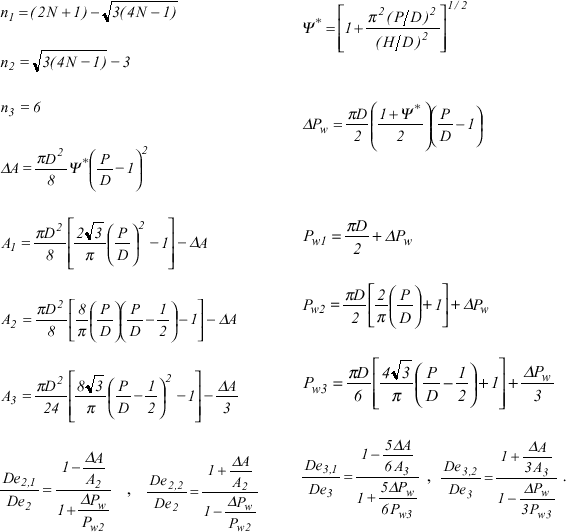
Finally, appendix I appendix I presents the formulae needed to evaluate the several geometrical parameters of the different subchannels for this type of fuel element.
Appendix 1
Manuscript received: May 1999, Technical Editor: Angela Ourívio Nieckele.
- Cheng, S.K. and Todreas, N.E., 1985, "Hydrodynamic Models and Correlations For Wire-Wrapped LMFBR Bundles and Subchannel Friction Factors and Mixing Parameters", Nuclear Eng. Design, Vol. 92, pp. 227.
- Chiu, C. et al., 1979, "Pressure Drop Measurements in LMFBR Wire-Wrapped Blanket Bundles", Trans. ANS, Vol. 22, pp. 541-543.
- Chiu, C. et al., 1980, "Turbulent Flow Split Model and Supporting Experiments for Wire-Wrapped Core Assemblies", Nuclear Technology, Vol. 50, pp. 40-52.
- Engel, F.C. et al., 1979, "Laminar, Transition and Turbulent Parallel Flow Pressure Drop Across Wire-Wrap-Spaced Rod Bundles", Nucl.Sci.Eng., Vol. 69, pp. 290-296.
- Ginsberg, T., 1972, "Forced-Flow Interchannel Mixing Model for Fuel Rod Assemblies Utilizing a Helical Wire-Wrap Spacer System", Nucl.Eng.Design, Vol. 22.
- Hawley, J.T. et al., 1980, "Subchannel and Bundle Friction Factors and Flow Split Parameters for Laminar, Transition and Turbulent Longitudinal Flows in Wire-Wrap Spaced Hexagonal Arrays", ANS/ASME/NRC Intl.Topical Meeting on Nuclear Reactor Thermal-Hydraulics, NUREG/CP-0014, Vol. 3, Saratoga, NY, pp. 1766-1788.
- Khan, E. and Todreas, N. E., 1973, "A Review of Recent Analytical and Experimental Studies Applicable to LMFBR Fuel and Blanket Assembly Design", Report MIT-COO-2245-4.
- Novendstern, E.H., 1972, "Turbulent Flow Pressure Drop Model for Fuel Rod Assemblies Utilizing a Helical Wire-Wrap Spacer System", Nucl.Eng.Design, Vol. 22, pp. 19-27.
- Rehme, K., 1973, "Pressure Drop Correlations for Fuel Element Spacers", Nuclear Technology, Vol. 17, pp. 15-23.
- Rogers, J.T. and Todreas, N.E., 1968, "Coolant Interchannel Mixing in Reactor Fuel Rod Bundles Single-Phase Coolants", ASME Winter Meeting.
- Schlichting, H., 1968, "Boundary-Layer Theory", Ed. McGraw-Hill, 6th Edition.
- Todreas, N.E. and Kazimi, M.S., 1993, "Nuclear systems I _ Thermal Hydraulic Fundamentals", Ed. Taylor & Francis, 2nd Edition.
- Tong, L.S., 1968, "Pressure Drop Performance of a Rod Bundle", in Heat Transfer in Rod Bundle, ASME Winter Annual Meeting, NY.
appendix I
Publication Dates
-
Publication in this collection
11 Oct 2001 -
Date of issue
Dec 1999
History
-
Received
May 1999


