Abstracts
This paper presents an intelligent lighting system for bus interior environment using LEDs (Light Emitting Diodes) controlled through an automotive communication network. The system consists of a master central control and slave lighting modules, using a LIN protocol (Local Interconnect Network) to perform communication. This network is a low cost alternative to the proposed system requirements, due to its low bit rate and physical needs. Each slave is an independent lighting module that supplies a group of LEDs and measures the environment lighting level. The master sets LEDs module parameters (slaves), such as the state (on/off) and desired lighting level. Besides, the master makes the user interface and establishes communication with other bus systems through a CAN (Controller Area Network) gateway. This paper presents a complete logical description, including block and state diagrams, a physical description and some relevant experimental results of the proposed system.
Automotive application; communication network; light emitting diode; lighting; microcontroller
Este trabalho apresenta um sistema de iluminação inteligente para interiores de ônibus utilizando LEDs (diodos emissores de luz) controlados através de uma rede automotiva de comunicação de dados. O sistema consiste em um controle central (mestre) e módulos de iluminação escravos, utilizando-se um protocolo de comunicação do tipo LIN para efetuar a comunicação. Esta rede é uma alternativa de baixo custo para o sistema proposto, devido às suas características físicas e baixa taxa de transferência de dados apresentada. Cada nó escravo é um módulo de iluminação independente que controla um grupo de LEDs e mede o nível de iluminação ambiente. O nó mestre é responsável pelo ajuste dos parâmetros dos módulos de LEDs (escravos), tais como o estado (liga/desliga) e nível de iluminação desejado. Além disso, o nó mestre proporciona uma interface com o usuário do sistema e estabelece comunicação de dados com outros sistemas eletrônicos embarcados, através de uma porta de comunicação com uma rede do tipo CAN. Este artigo apresenta uma descrição lógica completa do sistema, através de diagramas de blocos e de estados, além de uma descrição física e alguns resultados experimentais relevantes.
Aplicação automotiva; diodo emissor de luz; iluminação; microcontrolador; rede de comunicação
ELETRÔNICA DE POTÊNCIA
Omnibus interior lighting system using LEDs and automotive communication network
Murilo Cervi; Douglas Pappis; Alexandre Campos; Ricardo Nederson do Prado
GEDRE-PPGEE-UFSM Avenida Roraima, nº 1000 - Cidade Universitária. CEP 97105-900 - Santa Maria RS; cervi@ieee.org; douglasp@mail.ufsm.br; campos@ct.ufsm.br; rnprado@ieee.org
ABSTRACT
This paper presents an intelligent lighting system for bus interior environment using LEDs (Light Emitting Diodes) controlled through an automotive communication network. The system consists of a master central control and slave lighting modules, using a LIN protocol (Local Interconnect Network) to perform communication. This network is a low cost alternative to the proposed system requirements, due to its low bit rate and physical needs. Each slave is an independent lighting module that supplies a group of LEDs and measures the environment lighting level. The master sets LEDs module parameters (slaves), such as the state (on/off) and desired lighting level. Besides, the master makes the user interface and establishes communication with other bus systems through a CAN (Controller Area Network) gateway. This paper presents a complete logical description, including block and state diagrams, a physical description and some relevant experimental results of the proposed system.
Keywords: Automotive application; communication network; light emitting diode; lighting; microcontroller.
RESUMO
Este trabalho apresenta um sistema de iluminação inteligente para interiores de ônibus utilizando LEDs (diodos emissores de luz) controlados através de uma rede automotiva de comunicação de dados. O sistema consiste em um controle central (mestre) e módulos de iluminação escravos, utilizando-se um protocolo de comunicação do tipo LIN para efetuar a comunicação. Esta rede é uma alternativa de baixo custo para o sistema proposto, devido às suas características físicas e baixa taxa de transferência de dados apresentada. Cada nó escravo é um módulo de iluminação independente que controla um grupo de LEDs e mede o nível de iluminação ambiente. O nó mestre é responsável pelo ajuste dos parâmetros dos módulos de LEDs (escravos), tais como o estado (liga/desliga) e nível de iluminação desejado. Além disso, o nó mestre proporciona uma interface com o usuário do sistema e estabelece comunicação de dados com outros sistemas eletrônicos embarcados, através de uma porta de comunicação com uma rede do tipo CAN. Este artigo apresenta uma descrição lógica completa do sistema, através de diagramas de blocos e de estados, além de uma descrição física e alguns resultados experimentais relevantes.
Palavras-chave: Aplicação automotiva, diodo emissor de luz, iluminação, microcontrolador, rede de comunicação.
1 INTRODUCTION
The necessity for intelligent lighting systems has increased significantly in the last years. Lighting consumers have required versatile systems, with several functions that adequate the lighting parameters according to each situation, although some of these systems require devices with specific characteristics to become feasible, such as robustness and long useful life.
Light emitting diodes (LEDs) play an important role about new lighting systems, owing to the recent technology increasing and future prospect (Zorpette, 2002). These devices provide several advantages to the conventional lighting sources, as robustness, long useful life, absence of heating, minimized size and constant current supply. It results in a simplified power supply design and brings feasible the implementation of microcontroled lighting systems.
In distributed lighting system, the use of small lighting sources brings the need for a distributed control system. Communication networks may satisfy this requirement through microcontrollers dedicated to the application. Moreover, the use of communication network allows a full control of the lighting parameters and brings versatility to the system.
This paper proposes an automotive lighting system using LEDs controlled through an automotive communication network. The system is applied to omnibus interior lighting, and it is easily adapted to other applications with similar characteristics, as building corridor, for example, without the need for significant changes.
This application demands some special characteristics, as environment comfort, further on simple control, low voltage supply, robustness, low EMI emission and long useful life. Further on these required characteristics, LEDs enable mitigated turn on and turn off, which reduces the lighting shock in each bus stop by increasing the transient time between the minimum and the maximum lighting level.
The distributed lighting sources are controlled from a central panel through the use a LIN (Local Interconnect Network) protocol, which is a low cost alternative communication network. A simple and informative user interface brings versatility to the control system, through the use of timers and sensors.
The structure of this paper is the following: Section 2 presents semiconductor lighting devices, with its correlated characteristics and applications; section 3 presents an automotive communication protocols overview; section 4, the proposed lighting system description; section 5, the experimental results and section 6 presents the paper conclusions.
2 SEMICONDUCTOR LIGHTING DEVICES
LEDs are semiconductor lighting sources that present small size, with different package type and luminous characteristics. The wavelength of the monochromatic light emitted from an LED is determined by chemical elements combined to the semiconductor crystal. It makes possible the light emission in any wavelength in spectrum, since these elements are changed (Sheu et alii, 2003). In applications which colored light is required, LEDs offer directed colored light from source, without the need for colored filters, which block the light flux when it is not of the desired wavelength.
The absence of fragile components, as gas or filament, brings some special characteristics to these lighting sources, as robustness to shock and vibrations, long useful life and reduced environment heating when compared to filament lamps.
Nowadays, LED luminous efficacy reaches about 40 lumens per watt, and it has been increased year by year due to the researches on semiconductor lighting technology (Tsao, 2004). Moreover, the directed luminous flux results more efficient use of light on target than incandescent bulb, which emits luminous flux in all directions.
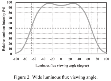
Distinct packages mean different luminous flux viewing angles. Each application requires different LEDs, depending on the illuminated surface. Figure 1 and figure 2 show different LED luminous flux viewing angle. Each LED is suitable for different applications. Figure 1 presents a narrow viewing angle, and this LED is proper to directed lighting application, as reading lighting and location sign. Figure 2 presents a wide viewing angle, being the environment lighting its most suitable application.
The continuous current and low voltage supply bring these devices to be controlled directly from a battery, using just a current limiter. It makes the LED an interesting alternative to be used in automotive applications, unlike fluorescent lamps, which require inverters to be supplied from a battery and present fragile bulbs. No starting circuit is required and LEDs work with low and safe voltages (Rico-Secades et alii, 2005).
Another point to be addressed is that LEDs can be dimmed from null to the maximum lighting level through the forward current control without damage its useful life. The ignition in any power level, from zero to the nominal value, does not demand any special igniter circuit but a controlled current limiter, as a PWM waveform with duty cycle control. Furthermore, the use of an active current limitter eliminates the necessity of using magnetic components in the system and avoids EMI emission.
3 AUTOMOTIVE COMMUNICATION PROTOCOLS
Automotive communication networks are used in order to enable the control of several electronic systems from a central control. The information sharing between different systems reduces redundant information occurrence, which optimizes and simplifies the electrical installation in the vehicle.
Each communication protocol presents different characteristics that make its use suitable to different applications (Leen et alii, 1999). Main characteristics are robustness, reliability, data rate and cost per addicted node.
The use of hierarchical network brings cost per node reduction, when using different communication protocols. The main network needs more complex characteristics and high bit rate to establish several systems control, while the sub network has to support just the specific system requirements.
One of the most used automotive communication protocols is CAN, which presents versatility due to the range of possible configurations. The use of a LIN network is a low cost alternative as a CAN sub network (Nolte et alii, 2005). It makes practicable the use of several slave nodes as sensors and low bit rate network.
Some specifications brings low cost characteristic to LIN (Ruff, 2003), as: low bit rate, that is enough to lighting system control; self synchronization between the nodes, without the necessity for crystal or ceramic resonator in each slave node (on-chip oscillators present the necessary accuracy for slave clock); and communication interface based on SCI (Serial Communication Interface), which is presented in most low cost microcontrollers.
The functional addressing makes possible to insert any slave to the LIN network, or remove from, without the necessity for any changes at the other nodes. It is denominated as a "plug and play'' system.
4 LIGHTING SYSTEM DESCRIPTION
4.1 System Overview
The system application is omnibus interior lighting, fully managed from the bus central control through the established communication network. The user sets the lighting parameters and the system dynamic behavior through an interface. Thus, the user programs the lighting according to the desired settings.
The system is divided into three subsystems, according to each role: the main lighting, responsible for the environment lighting; the help lighting, which helps the passengers to move around the hall without disturbing; and the read lighting.
Each subsystem is controlled independently, and there are some previous configurations for user choice, which determine the settings of each subsystem.
The changeable main and help lighting parameters are lighting level, timing, and mitigated turn on and turn off. The read lighting control is private, and the purpose of the central control is just to enable that.
The use of LEDs makes possible to turn the lights on progressively, from a null light level to the nominal intensity of the device, or a dimmed level, without decrease its useful life. It reduces the visual shock happened during overnight travel.
Concerning the LIN network, the slaves are independent lighting modules that supply the LEDs arrangements and measure the environment lighting level, as shown in figure 3.
The master sets slaves parameters through the user interface and establishes communication with other bus systems through a CAN gateway.
4.2 Physical Structure
The physical structure of the system is shown in figure 4, which indicates the master and slave nodes and the network physical layers used to link that.
Each node presents a microcontroller that realizes the specific node functions and establishes communication to the respective network, as described in Cervi et alii (2005).
The master node is composed of a microcontroller that fulfills both LIN and CAN communication protocols. Therefore, it needs an SCI module (serial communications interface) and a communication controller module implementing a CAN protocol (MSCAN).
On the other hand, the slave nodes fulfill only the LIN communication protocols and, due to the similar functions performed by each slave node, they are composed of similar microcontrollers, simpler and cheaper than the master node microcontroller.
Further on communication functions, each slave microcontroller controls the supplying of a LED group of about six LEDs in a series arrangement. It controls the LEDs lighting level through a PWM signal applied to a bipolar transistor at linear operation mode, as shown in figure 5. This lighting level is set by the user and is guaranteed through the use of lighting sensors using LDR (light dependent resistor) as presented in Michel et alii (2002).
An amplifier circuit "Amp'' is used in order to amplify the low current PWM signal supplied from the microcontroller. It provides the correct voltage to Rb and ensures the expected current Ib, wich drives the LEDs forward current Ic.
4.3 Master Node Structure
The master node establishes a user interface and the communication to each slave node through the LIN network.
The user interface is composed of a panel with one power switch, four configuration switches, and an LCD Display - a liquid crystal display of 2 lines with 16 characters -, as shown in figure 6. This interface can be done through the CAN network, using an existing omnibus central panel instead of using the control panel shown in figure 6.
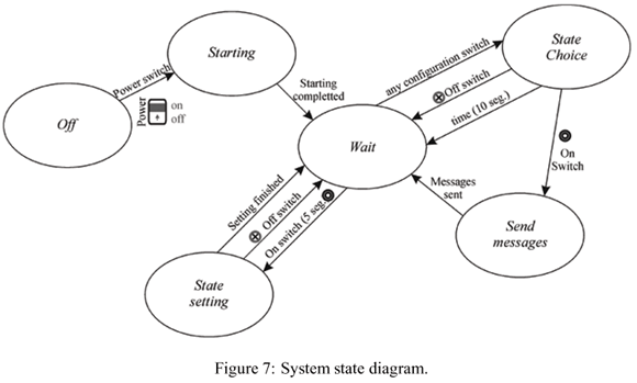
Figure 7 shows the state diagram of the master node behavior.
There are six states, described as follow:
Off: No electric energy on the system.
Starting: LIN, LCD and microcontrollers software inicializations.
Wait: Display on, showing the system current state.
State choice: Select a preset lighting state, with parameters configured for each subsystem, as shown in figure 8.
Send messages: Establish communication between the master node and the slave nodes, sending messages according to the state choice.
State setting: Configure the lighting state parameters, as timing, enabling, and lighting level for each lighting subsystem. The state setting algorithm implementation is shown in figure 9.
The state transitions are described in figure 7. These transitions are obtained using the configuration switches and through the software, at the end of some tasks and timing for appropriate user operation.
4.4 Slave Node Structure
The slave nodes are independent lighting modules that supply a group of LEDs and measure the environment lighting level. Then, a slave node is a lighting system controller, whose parameters are set by the master through the LIN network.
Figure 10 shows the flowchart of a slave node algorithm. It consists of a starting block, a turn on choice block, a timing option, lighting sensor, lighting reference compare and the power setting (PWM configuration).
The main and help subsystems fulfill the timing. When the time ends, the main subsystem turns the LEDs off, while the help subsystem dimming them, in order to mitigate the lighting during nightly travels.
5 EXPERIMENTAL RESULTS
Two prototypes were implemented using different LEDs, which the viewing angles are shown in figure 1 and figure 2. These LEDs presented similar lux values when compared each one, although the power are different, as shown in table 1. The reason for that is the different viewing angle of the used LEDs. In order to light the same surface, with the same lux, it is needed a grater number of the narrow LEDs.
The luminous flux viewing angle corresponds to the half of the LED maximum luminous intensity.
The choice of the right LED depends on the system application. The narrow LED is a good alternative to lighting systems that require a narrow light, whereas the use of the wide LED is indicated where a distributed light source is required, as environment lighting system.
Figure 11 shows a message sent through the LIN network. The header is sent by the master node, and the response is sent by any node connected to the LIN bus.
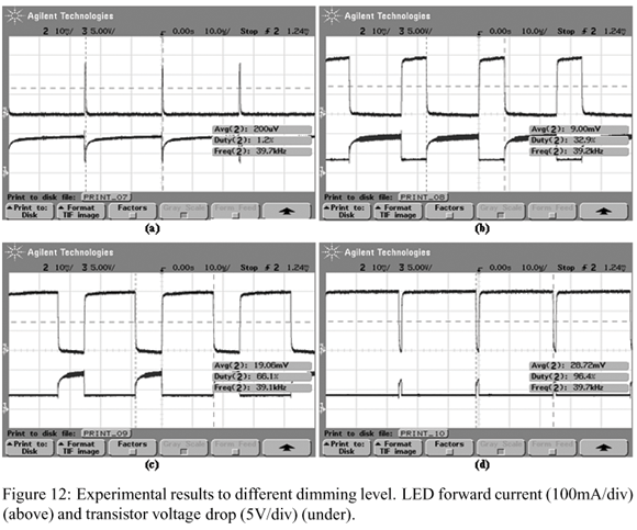
The dimming control was made through a pulsed width modulated forward current, in order to avoid unpredictable results and variation in LEDs performance.
The control of the LEDs forward current is performed by the slave node microcontroller. It comands the swiching of the transistor, wich operates in the active region during the conduction period in order to limit the current. During the block period, the transistor operates in the cutoff region.
The duty cycle and the average of the LED forward current are shown in figure 12, to further demonstrate the control of the light level.
6 CONCLUSION
This paper has proposed a versatile lighting system for bus interior environment using LEDs controlled through a low cost automotive communication network.
The proposed system presents the advantages of using LEDs, such as robustness and long useful life, avoiding the use of magnetic components, EMI and ambient heating. Furthermore, the use of LEDs simplifies the implementation of microcontroled lighting systems, which makes possible to obtain many control options and several system functions.
Besides, the use of an automotive network brings versatility to the system, making possible the integration of that with some other systems and, moreover, allowing a practicable installation.
The efficiency improvements and the costs reduction of semiconductor lighting devices are important topics to be addressed for futures system applications.
Artigo submetido em 14/03/2006
1a. Revisão em 08/05/06
2a. Revisão em 09/06/06
Aceito sob recomendação do Editor Associado Prof. Enes Gonçalves Marra
- Cervi, M., D. Pappis, T. B. Marchesan, A. Campos and R. N. do Prado (2005). A Semiconductor Lighting System Controlled through a LIN Network to Automotive Application. Conference Record of the 40th IAS Annual Meeting, Kowloon, Hong Kong, Vol. 3, pp. 1603-1608.
- Leen, G., D. Heffernan and A. Dunne (1999). Digital Networks in the Automotive Vehicle. Computing & Control Engineering Journal (December), Vol. 10, Issue: 6, pp. 257-266.
- Michel, A. L., D. Pappis, A. Campos and R. N. do Prado (2002). Electronic Ballast with Automatic Luminous Variation and Presence Detection using Microcontroller and Self-Oscillating Command. Conference Record of the 37th IAS Annual Meeting, Pittsburgh, Pennsylvania, Vol. 2, pp. 1071-1077.
- Nolte, T., Hans H. and Lucia lo B. (2005). Automotive Communications - Past, Current and Future. Conference on Emerging Technologies and Factory Automation, Catania, Vol. 1, pp. 985-992.
- Ruff, M. (2003). Evolution of Local Interconnect Network (LIN) Solutions. IEEE Vehicular Technology Conference, Orlando, Florida, Vol. 5, pp. 3382 - 3389.
- Rico-Secades, M., A. J. Calleja, J. Ribas, E. L. Corominas, J. M. Alonso, J. Cardesin and J. García-García (2005). Evaluation of a Low-Cost Permanent Emergency Lighting System Based on High-Efficiency LEDs. IEEE Transactons on Industry Applications, Vol. 41, issue: 5, pp 1386-1390.
- Sheu, J. K., S. J. Chang, C. H. Kuo, Y. K. Su, L. W. Wu, Y. C. Lin, W. C. Lai, J. M. Tsai, G. C. Chi and R. K. Wu (2003). White-Light Emission from Near UV InGaN-GaN LED Chip Precoated with Blue/Green/Red Phosphors. IEEE Photonics Technology Letters (January), Vol. 15, issue: 1, pp. 18-20.
- Tsao, J. Y. (2004). Solid-State Lighting: Lamps, Chips, and Materials for Tomorrow. IEEE Circuits and Devices Magazine (May/June), Vol. 20, issue: 3, pp 28-37.
- Zorpette, G. (2002). Let There Be Light. IEEE Spectrum magazine (September), Vol. 39, Issue: 9, pp 70-74.
Publication Dates
-
Publication in this collection
07 Mar 2007 -
Date of issue
June 2006
History
-
Reviewed
09 June 2006 -
Received
14 Mar 2006


