Abstract
This paper presents a study about the fracture mechanism of a ferritic stainless steel (UNS S44400 type) during a tensile test. The applied materials for the experimental procedures were 25 specimens of the steel, machined in the rolling direction. Each specimen was submitted to standard polishing procedures. One of the samples, in the original state, was structurally characterized by reflected light optical microscopy. The other samples were submitted to tensile tests with a constant displacement rate. Three samples were tested until failure (complete tests) and the others just until specific strain values, when the tests were interrupted and the samples were characterized by using optical and scanning electron microscopy. The main objective of these characterizations was to evaluate the structural damage evolution and to identify the fracture mechanism for the tested conditions. A methodology to quantify the damage evolution by surface roughness, identified by optical microscopy, was proposed. A new index - Damage by Diffuse Reflection Index (DRI) - was proposed to quantify the damage evolution in function of the specimen deformation. It was possible to confirm the ductile behavior of the studied steel and that the main fracture mechanism was the traditional dimpled rupture.
Keywords:
tensile test; failure mechanism; ductile fracture; damage evolution
1. Introduction
Ductile fracture is a common mode of fracture in engineering alloys. It has also been known as a dimpled, fibrous, or plastic fracture. A fracture by this mode usually involves the absorption of a large amount of energy. Ductile fracture is a non-trivial issue that affects the workability (formability) of engineering materials (Lassance et al., 2007LASSANCE, D., FABREGUE, F., DELANNAY, F., PARDOEN, T. Micromechanics of room and high temperature fracture in 6XXX Alloys. Progress in Materials Science, v. 52, p. 52-129, 2007.). The accurate prediction of a material's ductile fracture is thus of practical importance in the design and optimization of processes and products. There have been many reviews dealing with ductile fracture. Among them are that of Rosenfield (1968)ROSENFIELD, A. R. Criteria for ductile fracture of two-phase alloys. Metallurgical Reviews, v.13, p. 29-40, 1968., Low Jr. (1968)LOW, J. R. Effects of microstructure on fracture toughness of high strength alloys. Engineering Fracture Mechanics, v. 1, p. 47-53, 1968., Broek (1971), Schwalbe (1977)SCHWALBE, K.H. On the influence of microstructure on crack propagation mecha nisms and fracture toughness of metallic materials. Engineering Fracture Mecha nics, v. 9, p. 795-832, 1977., Howard/Willoughby (1981)HOWARD, WILLOUGHBY, A. A. Developments in Fracture Mechanics. Applied Science. v. 2, p.39-99, 1981., Wilsdorf (1983)WILSDORF, H. G. F. The ductile fracture of metals: a microstructural viewpoint. Materials Science and Engineering, v. 59, p. 1-39, 1983., Leslie (1983)LESLIE, W.C. Inclusions and mechanical properties. Transactions of the Iron and Steel Society, v.2, p.1-24, 1983., Van Stone et al. (1985)VAN STONE, R. H., COX, T. B., LOW, J. R., PSIODA, J. A. Microstructural aspects of fracture by Dimple rupture. International Metals Reviews, v. 30, p. 157-179, 1985., Godefroid/Bastian (1989GODEFROID, L. B., BASTIAN F. L. Uma análise crítica sobre modelos que envolvem a influência de inclusões na fratura dúctil. In: CONGRESSO ANUAL DA ABM, 44. 1989, Rio de Janeiro. Anais..., 1989. v. 1, p. 471-493.), Li et al. (2011)LI, H., FU, M.W., LU, J., YANG, H. Ductile fracture: experiments and computations. International Journal of Plasticity, v. 27, p. 147-180, 2011., and Lou/Huh (2013)LOU, Y., HUH, H. Prediction of ductile fracture for advanced high strength steel with a new criterion: experiments and simulation. Journal of Materials Processing and Technology, v. 213, p. 1284-1302, 2013..
From a microscopic viewpoint, ductile fracture is the integral manifestation of three stages: nucleation of internal voids during plastic flow, the growth of these voids with continued deformation, and finally their coalescence to produce complete rupture. The details of these three stages may vary widely in different materials and with the existing stress state during deformation. Similarly, the fractographic appearance of the final fracture surface is influenced by these same factors. These three procedures have been extensively studied experimentally, analytically and numerically.
The voids nucleation may occur in systems containing second-phase particles, by particle/matrix interface separation or by particle cracking. The interaction of slip and a second phase, usually less deformable than the matrix, leads to regions of highly localized stress, which cause cracking of the particle or interface decohesion (Bluhm/Morrissey (1965)BLUHM, J.I., MORRISSEY, R.J. Fracture in a tensile specimen. In: INTERNATIO NAL CONFERENCE ON FRACTURE, 1965. Japan. Proceedings of the First International Conference on Fracture. v.1, p.1739-1780, 1965., Gladman et al. (1971)GLADMAN, T., HOLMES, B., McIVOR, I.D. Effects of second-phase particles on strength, toughness, and ductility. The Iron and Steel Institute, 1971. 10p., Gurland (1972)GURLAND, J. Observations on the fracture of cementite particles in a spheroidized 1.05%C steel deformed at room temperature. Acta Metallurgica, v. 20, p. 735-741, 1972., Cox/Low (1974)COX, T. B., LOW, J. R. An investigation of the plastic fracture of AISI 4340 and 18 Nickel-200 grade maraging steels. Metallurgical Transactions, v. 5A, p. 1457-1470, 1974., Argon et al. (1975)ARGON, A.S., IM, J., SAFOGLU, R. Cavity formation from inclusions in ductile fracture. Metallurgical Transactions, v. 6A, p. 825-837, 1975.). The void nucleation can also occur at blocked slip bands in the absence of second-phase particles in systems of highly restricted, anisotropic deformation. Voids are formed when an intense deformation band impinges on a grain or twin boundary, and because of the limited slip systems the adjacent crystal is unable to accommodate the shear deformation. The boundary, which contains no inclusions, is first offset until the stresses at the leading edge become so great that the material separates and produces a void (Thompson/Williams (1977)THOMPSON, A.W., WILLIAMS, J.C. Nuclei for ductile fracture in titanium. In: FOURTH INTERNATIONAL CONFERENCE ON FRACTURE, 1977. Canada. Proceedings of the FOURTH INTERNATIONAL CONFERENCE ON FRACTURE, 1977. v.2, p.343-348., Van Stone et al. (1978)VAN STONE, R.H., LOW, J.R., SHANNON, J.L. Investigation of the fracture me chanism of Ti-5Al-2.5Sn at cryogenic temperatures. Metallurgical Transactions, v.9A, p.539-552, 1978., Wilsdorf et al. (1986)). Local stress concentrations due to strain incompatibilities in two different phases interfaces, like dual-phase steels, are also reported to cause void nucleation (Shen et al. (1986)SHEN, H.P., LEI, T.C., LIU, J.Z. Microscopic defonnation behaviour of martensitic -ferritic dua1-phase steels. Materials Science and Technology, v.2, p. 28-33, 1986., Suh et al. (1997)SUH, D., KWON, D., LEE, S., KIM, N. J. Orientation dependence of microfracture behavior in a dual-phase high-strength low-alloy steel. Metallurgical Transactions A. v. 28, p. 504-509, 1997., Ahmed et al. (2000)AHMED, E., TANVIR, M., KANWAR, L.A., AKHTER, J.I. Journal of Materials Engineering and Performance, v.9, p. 306-310, 2000., Erdogan (2002)ERDOGAN, M. The effect of new ferrite content on the tensile fracture behaviour of dual phase steels. Journal of Materials Science, v.37, p. 3623-3630, 2002., Kadkhodapour et al. (2011)KADKHODAPOUR, J., BUTZ, A., RAD, S. Z. Mechanisms of void formation du ring tensile testing in a commercial dual phase steel. Acta Materialia, v. 59, p. 2574-2588. 2011.).
There are at least two distinct mechanisms of stable void growth. In one, the cavity growth is controlled by plastic flow of the material matrix that surrounds the void-nucleating phase. In the second case, the first type of void growth is assisted by decohesion at smaller second-phase particles during the deformation process. The smaller second-phase particles can either be from the lower end of the size distribution of a single particle type or from a totally different phase having its own characteristic size distribution (Floreen/Hayden (1970)FLOREEN, S., HAYDEN, H.W. Some observations of void growth during the tensile deformation of a high strength steel. Scripta Metallurgica, v. 4, p. 87-94, 1970., Cox/Low (1974)COX, T. B., LOW, J. R. An investigation of the plastic fracture of AISI 4340 and 18 Nickel-200 grade maraging steels. Metallurgical Transactions, v. 5A, p. 1457-1470, 1974., Thomasson (1985)THOMASSON, P.F. Acta Metallurgica, v. 33, p. 1087-1095, 1985.).
Void coalescence occurs by either void impingement or by the void-sheet process. In the first case, coalescence of inclusion-nucleated voids can occur by the necking down of the matrix between voids until the ligament has no cross-sectional area. In the latter case, voids nucleate at a population of dispersed phases, generally smaller than the inclusions which nucleated the primary voids. The formation of void sheets aborts the otherwise stable void-growth process and thus diminishes toughness and ductility (Greenfield/Margolin (1972)GREENFIELD, M.A., MARGOLIN, A. The mechanism of void formation, void gro wth, and tensile fracture in an alloy consisting of two ductile phases. Metallurgical Transactions, v. 3A, p. 2649-2659, 1972., Brown/Embury (1973)BROWN, L.M., EMBURY, J.D. The initiation and growth of voids at second phase particles. The Microstructure and Design of Alloys. Cambridge: 1973. 5p., Cox/Low (1974)COX, T. B., LOW, J. R. An investigation of the plastic fracture of AISI 4340 and 18 Nickel-200 grade maraging steels. Metallurgical Transactions, v. 5A, p. 1457-1470, 1974., Weck/Wilkinson (2008)WECK, A., WILKINSON, D. Experimental investigation of void coalescence in me tallic sheets containing laser drilled holes. Acta Materialia, v. 56, p. 1774-1784, 2008..
In this context, this work aims to study the evolution of plastic deformation and microstructure damage in ferritic stainless steel samples of UNS S44400 grade (APERAM, 2012), through the tensile test. For this purpose, the surface of the samples was polished and properly observed with the use of optical microscopy and scanning electron microscopy. A single index related to the "strain roughness" of the samples is being proposed to characterize the mechanical behavior of the material and the damage evolution.
2. Material and experimental methods
A hot rolled sheet of an UNS S44400 ferritic stainless steel with 0.5mm thickness was supplied by the company APERAM South America. Its chemical composition was obtained using a THERMO SCIENTIFIC model ARL-4460 optical emission spectrometer. The microstructure was revealed with a modified Villela reagent (5g of picric acid, 100ml of ethylic alcohol, and 6ml of hydrochloric acid), and observed in a LEICA optical microscope coupled to a digital camera for image acquisitions and controlled by a Q-WIN software.
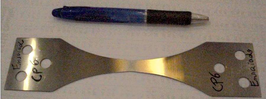
Tensile specimens with continuous radius between ends were prepared with the following dimensions: total length = 50mm; minimum width = 12.5mm; thickness = 0.5mm. Figure 1 shows an example of this geometry. This type of geometry was chosen to facilitate the monitoring of strain along the gage length and to ensure the fracture in the center of the specimen. The specimens had three holes in their heads, for coupling with the grips of the mechanical testing machine.
In order to adjust the tensile specimens for visual monitoring of their deformation during the tests, the surfaces were conveniently prepared by grinding and polishing as the usual metallographic practice. Specimens were sanded in special sandpapers from 400mesh to 1200mesh, and polished with alumina aqueous suspension with particle average size of 1μm and diamond paste with particle average size of 0.25μm.
Tensile tests were conducted on a 10ton MTS-810 servo-hydraulic testing machine interfaced to a computer for machine control and data acquisition. All tests were executed with a 5mm/min displacement rate. Three specimens were submitted to the complete tensile test, until fracture occurrence, to obtain the main mechanical properties of the steel. The remaining specimens were submitted to incomplete tensile tests, been interrupted with different strain levels: 1.2%, 9.7%, 12.2%, 14% and 16%.
After the tensile tests, all the specimens were analyzed with the LEICA optical microscope. The Q-WIN software was used to monitor the deformation process and to measure the "strain roughness" of the tested specimens. An Inspect-S50 scanning electron microscope was also used to characterize the superficial damage evolution and to confirm the ductile mechanism of the steel fracture.
The quantitative parameter proposed to characterize the damage evolution during the deformation process was named Diffuse Reflection Index (DRI). This index is related to the superficial roughness occurrence that increases with the strain level of the tensile specimen. Before the polished specimen strain (very low roughness), in an observation at the optical microscope with magnification of 200X, it is possible to observe that all the points in the field view were in focus, because all of them had a distance from the objective lens inside the field depth distance (Figure 3). However, as the specimens were strained and the roughness has increased, the topographic changes on sample surface create trough and crest areas that go out from the field depth distance, getting out of focus with a strong diffuse reflection profile.
Q-Win Software application to determine the strain roughness of a tensile specimen. Blue regions are the not focused areas.
In this context, the DRI parameter was defined as the area fraction with diffuse reflection in an optical microscope image obtained with a fixed magnification, i.e., the percentage of observed image that is not in focus due the roughness of the surface. Figure 2 exemplifies this procedure. Ten images with 200X magnification were captured at the middle of the strained specimens and the not focused areas were automatically identified and blue painted. Using the Q-WIN software, the blue areas were quantified by image analysis and the DRI index was calculated applying Equation 1.

3. Results and discussion
Table 1 presents the chemical composition of the studied stainless steel. This chemical composition meets the manufacturer's specification (APERAM, 2012). Only the chromium content is slightly below the specified (17.5%-18.5%). It is interesting to note the presence of Mo, which improves the corrosion resistance, and the bi-stabilization by Ti and Nb. The very low content of nickel gives this material a very competitive price.
Figure 3 presents an image (optical microscope) of a sanded and polished surface of the studied steel, without etching. It is possible to see a fine distribution of inclusions (small black points). Cracks and other volumetric defects, which could affect the structural integrity of steel, were not observed. Figure 4 presents the ferritic structure of the studied steel after etching with the modified Villela reactive. It is possible to observe a heterogeneous ferritic grain size distribution.
Figure 5 presents the conventional tensile test curve with average values obtained from three tests. Table 2 presents the main properties obtained from this test for this steel. It is important to comment that the obtained total strain is below the value specified by the manufacturer (APERAM, 2012), because the specimens used in this work do not followed the ASTM E8 standard for tensile test. The sheet was machined with a continuous concordance radius aiming to promote a strong stress concentration in the middle of the specimen. The specimen type was inspired by the ASTM E466 for fatigue test on metallic materials.
UNS S44400 average mechanical properties (YS - Yield Strength, TS - Tensile Strength, SF – Strain to fracture, AR - Area Reduction).
The lateral surface of all tested specimens was analyzed by optical microscope. Figures 6-11 show the corresponding micrographs. It is possible to see that the increase of deformation in the specimen causes a greater roughness on its surface. There is also an increase in the quantity and thickness of slip lines, arising from the slipping of crystallographic planes in the grains of the material.
Figure 12 presents the damage evolution indirectly measured by the Diffusion Reflection Index (DRI) as a function of specimen deformation, using the surface roughness of the specimens. The specimen without deformation (0%) corresponds to the as-received material, so it does not present damages. The 1.2% deformed specimen also did not present significant damages. Specimens with higher deformation presented significant superficial damages, especially for deformations higher than 10%. From this level of strain, the tensile strength of the material is being achieved, the necking process begins to operate in the specimen, and local roughness is evident.
Figure 13 shows an example of the necking development, for 14% of deformation. No significant differences were observed between samples with 15.5% and 16%, due to the evolution stage of necking caused by the advanced degree of microvoids coalescence. It is possible to observe that the higher the deformation, the higher the standard deviation obtained in experimental procedures. This occurs due to the higher deformation, more intense and localized is the deformation effects on surface (necking). As the proposed method for DRI determination consists in scanning different fields of view under an optical microscope; if the deformation signals are more localized, the DRI measured for each filed is not very similar. As a consequence, the standard deviation is higher.
Samples submitted to higher deformations were analyzed in a scanning electron microscope. Figures 14-17 present images obtained with SEM for 9.7%, 12.2%, 14% and 16% strained specimens, respectively.
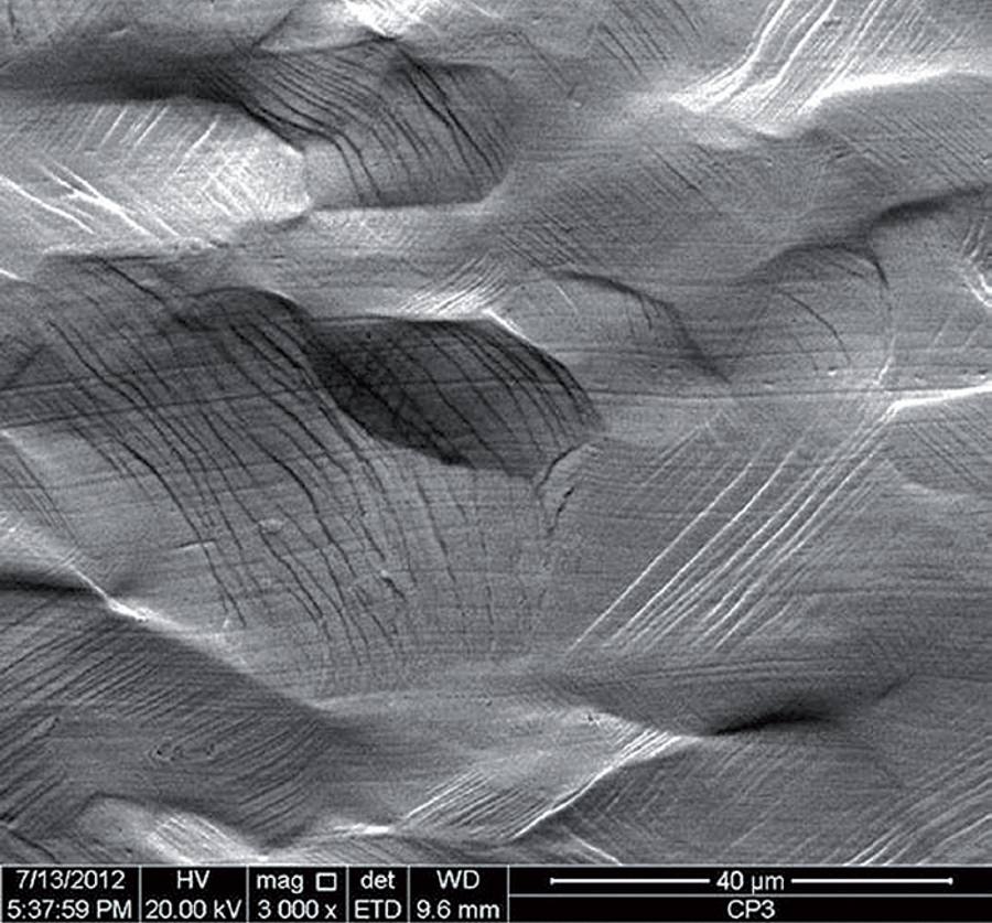
Figure 14 shows sets of deformation lines, each set with a specific orientation. This is due to each material grain presenting a well defined crystalline orientation and a preferential slip plan that may slip according to its position at solid bulk and applied force.
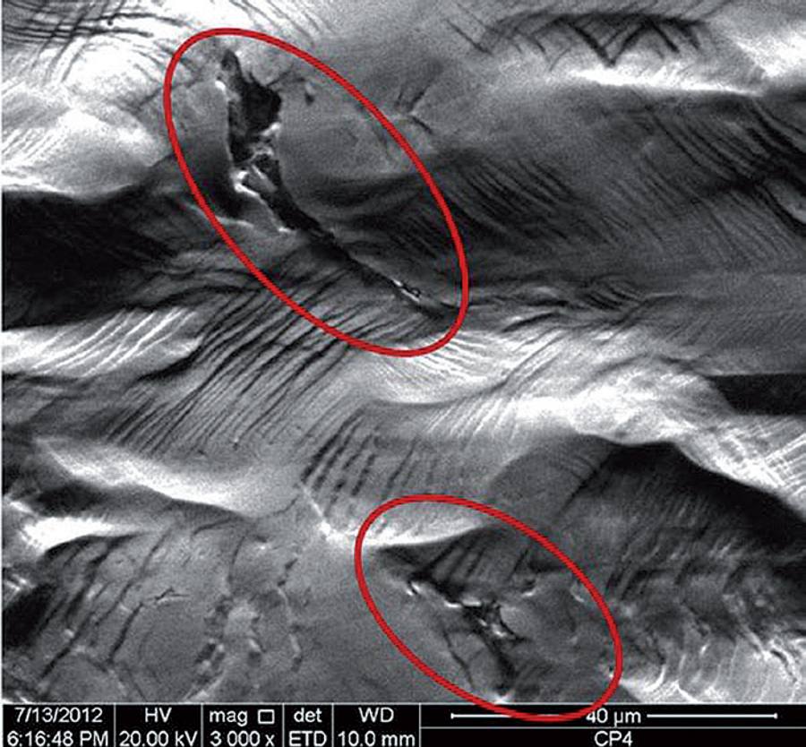
Figure 15 presents deformation lines and microvoid nucleation (red cicles). This Figure corresponds to 12.2% strained specimen, which is already plastic deformed in a non-uniform field. It is possible to note that for the studied stainless steel, the microvoid nucleation starts mainly in the deformation lines. Other researchers as Puttick (1959), Rogers (1960), Chen (1961) and Beevers & Honeycomb (1962) founded similar results for other metallic materials. They pointed out the deformation lines as a potential structural defect where voids can preferentially nuclei.
Figure 16 (14% strained specimen) shows large voids, that are formed by the coalescence between smallers voids, as described in literature.
Figure 17 (16% strained specimen) presents a crack iniciation due to microvoids coalescence. These observations confirm that the ductile fracture mechanism is nucleation, growth and coalescence of microavoids, in accordance to literature.
Aiming to characterize the studied steel fracture and prove the relationship between microstructural damage evolution and ductile fracture mechanism, all tested samples until failure were analyzed in a scanning electron microscope for a fractograph analysis. Figure 18 presents images of fracture surfaces where dimples are present, confirming the mechanism of nucleation, growth and coalescence of microvoids as the main way of the ductile fracture in UNS S44400 steel.
4. Conclusions
The proposed method for damage evaluation by the DRI index was satisfactory because it allowed to quantify and to compare different damage intensities as a function of specimen strain.
The proposed DRI index can be a potential tool, with easy application and low experimental cost, associated to optical and electronic microscopy, to characterize the microstructural damages in different metallic materials as a function of their strains.
The proposed DRI index can be tested as a tool to describe and understand the specimen damages caused by other mechanical damages, like fatigue. This method can be tested to describe de damage evolution as a function of material fatigue life, relating structural aspects with crack nucleation and propagation.
The UNS S44400 stainless steel has a ductile fracture when tested in tensile test at room temperature. The main observed fracture mechanism was nucleation, growth and coalescence of microvoids from deformation lines. Inclusions present in the sample appear to have no significant influence on voids nucleation.
5. Acknowledgements
The authors would like to thank APERAM South America for providing the material for the present research.
6. References
- AHMED, E., TANVIR, M., KANWAR, L.A., AKHTER, J.I. Journal of Materials Engineering and Performance, v.9, p. 306-310, 2000.
- ARGON, A.S., IM, J., SAFOGLU, R. Cavity formation from inclusions in ductile fracture. Metallurgical Transactions, v. 6A, p. 825-837, 1975.
- BLUHM, J.I., MORRISSEY, R.J. Fracture in a tensile specimen. In: INTERNATIO NAL CONFERENCE ON FRACTURE, 1965. Japan. Proceedings of the First International Conference on Fracture v.1, p.1739-1780, 1965.
- BROEK, D. The role of inclusions in ductile fracture and fracture toughness. Engine ering Fracture Mechanics, v. 5, p. 55-66, 1973.
- BROWN, L.M., EMBURY, J.D. The initiation and growth of voids at second phase particles. The Microstructure and Design of Alloys Cambridge: 1973. 5p.
- COX, T. B., LOW, J. R. An investigation of the plastic fracture of AISI 4340 and 18 Nickel-200 grade maraging steels. Metallurgical Transactions, v. 5A, p. 1457-1470, 1974.
- ERDOGAN, M. The effect of new ferrite content on the tensile fracture behaviour of dual phase steels. Journal of Materials Science, v.37, p. 3623-3630, 2002.
- FLOREEN, S., HAYDEN, H.W. Some observations of void growth during the tensile deformation of a high strength steel. Scripta Metallurgica, v. 4, p. 87-94, 1970.
- GLADMAN, T., HOLMES, B., McIVOR, I.D. Effects of second-phase particles on strength, toughness, and ductility The Iron and Steel Institute, 1971. 10p.
- GODEFROID, L. B., BASTIAN F. L. Uma análise crítica sobre modelos que envolvem a influência de inclusões na fratura dúctil. In: CONGRESSO ANUAL DA ABM, 44. 1989, Rio de Janeiro. Anais..., 1989. v. 1, p. 471-493.
- GREENFIELD, M.A., MARGOLIN, A. The mechanism of void formation, void gro wth, and tensile fracture in an alloy consisting of two ductile phases. Metallurgical Transactions, v. 3A, p. 2649-2659, 1972.
- GURLAND, J. Observations on the fracture of cementite particles in a spheroidized 1.05%C steel deformed at room temperature. Acta Metallurgica, v. 20, p. 735-741, 1972.
- HOWARD, WILLOUGHBY, A. A. Developments in Fracture Mechanics. Applied Science v. 2, p.39-99, 1981.
- KADKHODAPOUR, J., BUTZ, A., RAD, S. Z. Mechanisms of void formation du ring tensile testing in a commercial dual phase steel. Acta Materialia, v. 59, p. 2574-2588. 2011.
- KLASSEN, R.J., BASSIN, M.N., BAYONMI, M.R., WILSDORF, H.G.F. Materials Science and Engineering, v. 83, p. 39-44, 1986.
- LASSANCE, D., FABREGUE, F., DELANNAY, F., PARDOEN, T. Micromechanics of room and high temperature fracture in 6XXX Alloys. Progress in Materials Science, v. 52, p. 52-129, 2007.
- LESLIE, W.C. Inclusions and mechanical properties. Transactions of the Iron and Steel Society, v.2, p.1-24, 1983.
- LI, H., FU, M.W., LU, J., YANG, H. Ductile fracture: experiments and computations. International Journal of Plasticity, v. 27, p. 147-180, 2011.
- LOU, Y., HUH, H. Prediction of ductile fracture for advanced high strength steel with a new criterion: experiments and simulation. Journal of Materials Processing and Technology, v. 213, p. 1284-1302, 2013.
- LOW, J. R. Effects of microstructure on fracture toughness of high strength alloys. Engineering Fracture Mechanics, v. 1, p. 47-53, 1968.
- ROSENFIELD, A. R. Criteria for ductile fracture of two-phase alloys. Metallurgical Reviews, v.13, p. 29-40, 1968.
- SCHWALBE, K.H. On the influence of microstructure on crack propagation mecha nisms and fracture toughness of metallic materials. Engineering Fracture Mecha nics, v. 9, p. 795-832, 1977.
- SHEN, H.P., LEI, T.C., LIU, J.Z. Microscopic defonnation behaviour of martensitic -ferritic dua1-phase steels. Materials Science and Technology, v.2, p. 28-33, 1986.
- SUH, D., KWON, D., LEE, S., KIM, N.J. Metallurgical Transactions, v. 28A, p. 504-509, 1997.
- SUH, D., KWON, D., LEE, S., KIM, N. J. Orientation dependence of microfracture behavior in a dual-phase high-strength low-alloy steel. Metallurgical Transactions A v. 28, p. 504-509, 1997.
- THOMASSON, P.F. Acta Metallurgica, v. 33, p. 1087-1095, 1985.
- THOMASON, P. Three-dimensional models for the plastic limit-loads at incipient failure o f the intervoid matrix in ductile porous solids. Acta Metallurgica, v. 33, p. 1079- 1085. 1985 a
- THOMPSON, A.W., WILLIAMS, J.C. Nuclei for ductile fracture in titanium. In: FOURTH INTERNATIONAL CONFERENCE ON FRACTURE, 1977. Canada. Proceedings of the FOURTH INTERNATIONAL CONFERENCE ON FRACTURE, 1977. v.2, p.343-348.
- VAN STONE, R. H., COX, T. B., LOW, J. R., PSIODA, J. A. Microstructural aspects of fracture by Dimple rupture. International Metals Reviews, v. 30, p. 157-179, 1985.
- VAN STONE, R.H., LOW, J.R., SHANNON, J.L. Investigation of the fracture me chanism of Ti-5Al-2.5Sn at cryogenic temperatures. Metallurgical Transactions, v.9A, p.539-552, 1978.
- WECK, A., WILKINSON, D. Experimental investigation of void coalescence in me tallic sheets containing laser drilled holes. Acta Materialia, v. 56, p. 1774-1784, 2008.
- WILSDORF, H. G. F. The ductile fracture of metals: a microstructural viewpoint. Materials Science and Engineering, v. 59, p. 1-39, 1983.
Publication Dates
-
Publication in this collection
Apr-Jun 2016
History
-
Received
25 Nov 2015 -
Accepted
29 Mar 2016