Abstract
Several commercial scale coal gasification combined cycle power plants have been built and successfully operated during the last 5-10 years. Supporting research on materials of construction has been carried out for the last 20 years by EPRI and others. Emphasis was on metallic alloys for heat exchangers and other components in contact with hot corrosive gases at high temperatures. In this paper major high temperature corrosion mechanisms, materials performance in presently operating gasifiers and future research needs will be discussed.
coal gasification; syngas coolers; sulfidation; downtime corrosion; stainless steel
High temperature corrosion in gasifiers
Wate Bakker* * e-mail: wbakker@epri.com
EPRI 3412 Hillview Avenue Palo Alto, CA 94304, USA
ABSTRACT
Several commercial scale coal gasification combined cycle power plants have been built and successfully operated during the last 5-10 years. Supporting research on materials of construction has been carried out for the last 20 years by EPRI and others. Emphasis was on metallic alloys for heat exchangers and other components in contact with hot corrosive gases at high temperatures. In this paper major high temperature corrosion mechanisms, materials performance in presently operating gasifiers and future research needs will be discussed.
Keywords: coal gasification, syngas coolers, sulfidation, downtime corrosion, stainless steel
1. Introduction
Intensive development of gasification technology has been carried out since the early seventies1,2,3. At present several commercial or nearly commercial scale coal gasification combined cycle plants are in operation worldwide. These include plants based on the Texaco and Dow processes in the USA, a plant based on the PRENF10 (Krupp-Koppers) process in Spain and a plant based on the Shell process in the Netherlands. All present plants include entrained slagging gasifiers and cold gas cleanup equipment. In this type of gasifier the fuel, coal, petroleum coke or heavy oil bottoms, are pulverized and fed to the gasifier in dry or slurry form. Gasification is carried out at very high temperatures, above the melting point of the mineral matter in the fuel, usually at 1300-1600 °C. The raw hot gas, consisting mainly of CO and H2, with H2S as the major corrosive impurity, is cooled in syngas coolers and then water quenched to remove particulates and water soluble impurities such as NH3 and chlorides. After quenching, H2S is removed in one of several commercially available gas purification systems. The purified gas is then fed to a gas turbine combined cycle plant for combustion and electricity generation. Figure 1 shows a schematic of such a plant, which is quite complex. Several corrosion and erosion problems have occurred in various plants, mostly at the pilot plant stage. These include coal slurry erosion and corrosion in feed systems, refractory corrosion and erosion in gasifiers, high temperature corrosion in syngas coolers and aqueous corrosion in down stream and gas purification equipment. Most of the problems found are not unique to gasifiers, but have been encountered elsewhere and have been resolved using existing technology. However high temperature corrosion in syngas coolers is unique to gasifiers, especially when coal is used as the fuel, due to interaction between various impurities present in coal.
For the above reasons and the fact that this conference is dedicated to high temperature corrosion, this paper will concentrate on high temperature corrosion in syngas coolers.
Details on operating conditions in syngas coolers are provided in References 1 and 7. The composition of the raw syngas depends on the gasification process used and the fuel composition, especially its sulfur and chlorine content. The syngas composition of processes with water-coal slurry systems is typically (vol %) CO 35-45, CO2 10-15, H2 27-30, H2O 15-25, H2S 0.2 - 1.2. HCl 50-500 ppm; for a dry fed gasifier the CO content of the gas is considerably higher 62-64%, while the CO2 and H2O contents are generally less than 4%. Thus the oxygen partial pressure (PO2) of a syngas from slurry fed gasifier is considerably higher than that from a dry fed gasifier. However the syngas composition reflects the high temperature equilibrium composition at 1300-1500 °C, while the heat exchangers operate at 300-600 °C. This makes it difficult to calculate PO2 and PS2 values, since the gases are not in equilibrium at the metal temperature1. Heat exchanger syngas operating temperatures in present gasifiers are generally less than 450 °C, partly due to high temperature corrosion concerns and partially due to studies indicating that, with the present design, the use of higher heat exchanger temperatures is not cost effective.
2. Corrosion Mechanism/Laboratory Studies
The major corrosion mechanism in syngas coolers is sulfidation. Due to the low PO2 and relatively high PS2 of the raw syngas, the sulfidation rate of carbon and low alloy steels is too high to allow the use of these low cost materials. This is shown in Fig. 2, which contains information from laboratory as well as plant studies, with good agreement between the two. It is further observed that the corrosion rate of low alloy steels appears largely independent of the chlorine content of the coal. The plant data in Fig. 2 were obtained from coals or coal derived fuels with chlorine contents ranging from 0.05 to 0.3%, resulting in 100-600 ppm HCl in the syngas1. Laboratory tests confirm that HCl contents in this range do not increase corrosion rates, at least not under the highly reducing conditions present in gasifiers.
Due to the unacceptably high corrosion rates of low alloy boiler steels, stainless steel heat exchanger tubes, coatings or claddings must be used to provide low corrosion rates. Extensive laboratory corrosion studies on both model and commercial alloys have been reported earlier1,4 and will be summarized here. All experiments were done under isothermal conditions. It was found that the corrosion rate of stainless steels containing 20% or more Cr with or without various minor alloying elements, such as Si, Al and Ti did not simply increase with increasing sulfidation potential, as indicated by the PS2/PO2 ratio of the syngas, but also depended on the HCl content of the syngas, the presence of chlorides in deposits and alloy composition.
In the absence of HCl in the syngas, the corrosion loss indeed increases as a function of the PS2/PO2 ratio as shown in Fig. 3 for alloys 800 (20Cr - 32Ni-Fe, Al, Ti) and 310 (25Cr - 20Ni-Fe). Corrosion rates are relatively low and parabolic reaction kinetics are usually observed5,6. SEM/EDS analysis indicates that at high PS2/PO2 ratios, a somewhat protective Fe Cr2 S4 spinel is formed. At lower PS2/PO2 ratios this layer gradually changes to FeCr2O4. Below the FeCr2S6 layer an inward growing scale/precipitation zone is formed consisting of FeCr2(S,O)4 spinels, Cr2O3 and iron rich alloy remnants. This corrosion mechanism is labeled Type A corrosion and is shown schematically in Fig. 4.
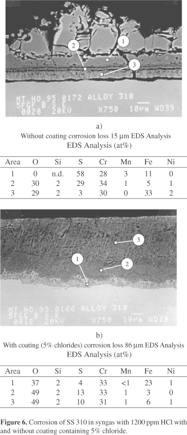
When HCl is present in the syngas the corrosion mechanism changes considerably as is shown in Fig. 5. Alloys with a relatively low chromium content such as alloy 800 now show a maximum corrosion rate at a log PS2/PO2 ratio of about 18, while alloys with a higher chromium content or similar oxide forming alloying elements such as Al or Si are relatively less affected by the addition of HCl to the gas. SEM/EDS analysis of Alloy 800 after exposure to a syngas with a log PS2/PO2 ratio of about 18 and a HCl content of 400 ppm indicated the absence of a protective FeCr2S4 scale. An outward growing FeS rich scale is present on top of an inward growing porous Cr2O3 rich scale containing Fe(Ni)S, which appears non protective. This corrosion mechanism is labeled Type B corrosion and is also shown schematically in Fig. 4. Further studies have shown that the onset of the less desirable Type B corrosion depends on the amount of oxide forming alloying elements in the alloy, the amount of HCl in the syngas and the presence of chlorides in deposits, which probably increases the PCl2 near the metal surface. For instance, the corrosion loss of stainless steel 310 after 164 h exposure to syngas with a log PS2/PO2 ratio of 18.5 and 1200 ppm is about 15 µm. However when a deposit containing 5% chloride is present the corrosion loss increases to 86 mm and the corrosion mechanism changes from Type A to Type B as shown in Fig. 6.
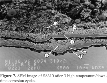
Aqueous corrosion during downtime can further increase overall corrosion rates in the presence of chloride containing deposits. During downtime hygroscopic chlorides can migrate through cracks in the scale to the scale/metal interface and form an FeCl3 rich layer beneath the scale. During heat up the FeCl3 layer causes spalling of the protective Cr2O3 rich scale and a new outward growing FeS rich scale and inward growing Cr2O3 rich scale is formed. This sequence repeats itself during each thermal cycle. Figure 7 shows the scale microstructure after three 200 h high temperature cycles and three 24 h downtime periods in humid air at 400 °C.
From the laboratory experiments described above, it is clear that the high temperature corrosion of stainless steels in syngas environments is complex and not readily predictable from simple gas/solid reaction mechanisms, especially when HCl is present in the gas and/or chlorides in the deposit.
3. Long Term Performance of Materials in Service
Laboratory tests are usually conducted at atmospheric pressure under isothermal conditions for a few hundred to a few thousand hours. Materials and components of electric power plants should last at least 100,000 h. In syngas coolers they are also exposed to elevated pressures, 40-60 atm, with significant thermal gradients. Thus laboratory tests are useful to determine corrosion mechanisms, and guide alloy selection, but are generally not suitable to predict actual corrosion rates. For this reason, EPRI has cooperated with several gasifier operators to obtain long term corrosion rate data in various pilot and commercial size gasification plants. Several materials have been exposed in various gasifiers for over 50,000 h7,8,9,10. Individual tests have ranged from 2000 to 17,000 h, at temperatures ranging from 300-550 °C.
In general, the corrosion mechanisms found in laboratory tests are also found in service, i.e., Type A corrosion under highly sulfidizing conditions at relatively low HCl levels, Type B corrosion under less sulfidizing conditions, at somewhat higher HCl levels and high rates of corrosion due to scale spallation when chlorides are present in the deposits, Fig. 8 shows an example of pitting and scale spallation of 310 stainless steel after 17,000 h exposure in a Texaco process gasification plant.
In the absence of scale spallation stainless steels containing at least 20%Cr generally provide a satisfactory corrosion rate of about 0.1 mm/yr or less in the 300-400 °C temperature range at which most heat exchanger surfaces in syngas coolers operate (Fig. 9). Corrosion mechanisms ranged from Type B corrosion for the lower Cr steels to Type A corrosion for steels with a higher Cr content such as 310.
When scale spallation due to chloride migration to the scale/metal interface occurs, corrosion rates increase considerably even at relatively low temperatures. Figure 10 shows the corrosion loss of the 310 stainless steel of Fig. 8, as a function of time. The rate is linear and is about 0.25 mm/yr. Here a Mo containing alloy such as Sanicro 28 (27Cr, 32Ni, 3.5%, Cu) is a better choice because it has a parabolic corrosion rate, with less than 0.25 mm loss after 17,000 hr exposure. When the fuel gasified has very high Cl levels extremely high corrosion rates are possible. This is illustrated in Fig. 11, which gives the results of a 5500 h exposure tests in a gasifier using a fuel containing 0.2-0.5% Cl. Here stainless steels have completely unacceptable corrosion rates and Mo containing alloys, preferably with a high Ni content such as Alloy 625 are the only acceptable materials. It is interesting to note that Alloy 625 is also the preferred alloy for waste to energy plants, where chlorine is the major corrodent under oxidizing conditions11.
Field corrosion data from various gasifiers indicate that metal wastage rates experienced so far will not lead to catastrophically high corrosion rates. When sulfidation is the only or major corrosion mechanism (Type A corrosion) corrosion rates less than 0.1 mm/yr are generally experienced for steels with >20% Cr at temperatures below 400 °C. Thus Alloy 800 (20Cr, 32Ni, Al, Ti), which is code approved for boiler service would be an economical choice and is indeed frequently used. However when the Cl content of the fuel is somewhat higher and the syngas is less sulfidizing, Type B corrosion can lead to highly increased corrosion rates. Under these conditions Alloy 800 and especially the weld material used for this alloy, INCO 82 (20 Cr, Ni, Nb) are less suitable and alloys with a higher Cr content are needed. 310 stainless steel has an adequate corrosion resistance, but is not approved for boiler service, due to potential waterside corrosion problems. Sanicro 28 is code approved and is also more resistant to Cl induced scale spallation. It is therefore the logical choice for application where Type B corrosion or scale spallation is likely.
In isothermal laboratory corrosion tests, scale spallation under Cl rich deposits is observed only in tests combining exposure at high temperature, with shorter periods of exposure to humid air (downtime corrosion). Similar scale spallation is also frequently found in service, but it also occurs when exposure to aqueous corrosion conditions is infrequent, i.e., when the plant operates continuously with only 1 or 2 shutdown year. Recently corrosion tests were carried out under thermal gradients to study waterwall corrosion in boilers12. It was found that chloride species in deposits can also move to the metal-scale interface and cause scale spallation when a thermal gradient is present, especially when the thermal gradient is steep enough to cause melting of the chloride mixture. Thus, we now believe that aqueous corrosion during downtime is not the only cause of scale spallation, but that thermal gradients in deposits may be a more likely culprit, especially in commercial gasifiers, where downtime is infrequent.
Finally it should be noted that all fuels used for present and future gasification plants can have dangerous Cl levels. Refinery wastes, petroleum coke and heavy oil bottoms have nominally low Cl levels. However "Phantom chlorides" have become a problem in refineries13. In one of our exposure tests using heavy fuel oil, nominally free of Cl, spallation due to chlorine corrosion was also experienced. The chlorine content of most coal is relatively low 0.1% or less. However the resulting HCl levels during gasification are much higher than in boilers and chlorides are frequently found in heat exchanger deposits, when gasifying coals with Cl contents as low as 0.1%.
4. Conclusions
1. Commercial scale gasification power plants have operated trouble free for long periods of time and using commercially available steels.
2. Corrosion losses due to high temperature sulfidation alone are generally low enough to provide acceptable long term service, especially when the Cr content is 20% or higher.
3. The presence of chloride rich deposits can cause scale spallation, resulting in accelerated corrosion. When this occurs common stainless steels have linear corrosion rates and Mo containing steels are preferred. They have more adherent scales and exhibit parabolic corrosion rates.
Received: September 2, 2002
Revised: September 4, 2002
Presented at the International Symposium on High Temperature Corrosion in Energy Related Systems, Angra dos Reis - RJ, September 2002
- 1. Bakker, W.T. Effect of Gasifier Environment on Materials Performance, Materials at High Temperatures 11 (1-4), p. 90, 1993.
- 2. Liere, J. van Present Status of Advanced Power Plants. Materials at High Temperatures 14 (2,3), p. 7, 1997.
- 3. Bakker, W.T. Present Status of Coal Gasification Technology, Proc. Materials for Coal Gasification, V. Hill, S. Dapkunas, W. Bakker, Ed., October 1987, ASM International, 1988.
- 4. Bakker, W.T. The Effect of Chlorine on Mixed Oxidant Corrosion of Stainless Steels, Mat. At High Temperature, v. 14, n. 3, p. 197, 1997.
- 5. Norton, J. et al., Proc. Heat Resistant Materials II, K. Natesan, P. Ganesan and G. Lai, eds., ASM International, p. 111, 1995.
- 6. John, R.C. et al., Materials at High Temperatures, 11(1-4), p. 124, 1993.
- 7. Bakker, W.T.; Stringer, J. Mixed Oxidant High Temperature corrosion in Gasifiers and Power Plants, Materials at High Temperature, v. 14, n. 2, p. 101, 1997.
- 8. Bakker, W.T.; Kip, J.B.M.; Schmitz, H.P. Materials at High Temperatures 11(1-4), p. 133, 1993.
- 9. Schellberg, W. et al., Materials at High Temperatures 14(2), p. 159, 1997.
- 10. Fahrion, M.E. Materials at High Temperatures, 11(1-4), p. 107, 1993.
- 11. Sorell, G. Materials at High Temperatures, 14 (2,3), p. 37, 1997.
- 12. Bakker, W.T.; Blough, J.E.; Seitz, W.; Kung, S.C. "The Effect of Deposits on Waterwall Corrosion" to be published in proc. Materials for Advanced Power Engineering, Liege, 2002.
- 13. Veasey, M.V. "Phantom Chlorides Create Real Problems for Refineries", Materials Performance, May 2002, p. 17-19, NACE International.
Publication Dates
-
Publication in this collection
25 May 2004 -
Date of issue
Mar 2004
History
-
Received
02 Sept 2002 -
Accepted
04 Sept 2002