Abstract
Ni/nano-Al2O3 composite coating by pulse electrodeposition method has been used for coating on cast iron liner material. The hardness has been increased from 308 HV to 1050 HV through conventional Watts bath and by applying Taguchi's optimization technique with optimum parameters of pulse frequency 120 Hz, duty cycle 40% and peak current density 0.7A/cm2. The lubricant's pH (4) and stirring speed (400 rpm) are the foremost parameters for increasing the hardness of the coating. Furthermore, the pulse current (PC) produces homogeneous distribution of Al2O3 particles in the Ni matrices. The chemical composition, surface morphology, crystal structure, adhesion, coating thickness and the corrosion resistance of the optimized liner specimen of deposited Ni/nano-Al2O3 coatings were evaluated by Optical Emission Spectrometer (OES), Scanning Electron Microscopy (SEM), X-ray diffraction (XRD), ASTM D 3359-97, Metallurgical Microscope (ASM standards) and ASTM B117-07 standards.
Keywords:
Pulse-eletrodepositon; Ni-nanoAl2O3 composite coatings; Corrosion; Crystal structure; Microhardness; Microstructure
1. Introduction
Wear is an important parameter for the engine cylinder liner in an automobile. One of the best ways to reduce the wear on the liner is to increase the hardness through some wear-resistant composite coatings. Wear in most cases occurs through surface interaction at asperities and is a complex process influenced by a number of factors including the metallurgy of contacting materials, surface texture, operating conditions of the components, load, speed, temperature, environment, and lubricant formulations11 Karamis MB, Yildizli K, Çakirer H. An evaluation of surface properties and frictional forces generated from Al-Mo-Ni coating on piston ring. Applied Surface Science. 2004;230(1-4):191-200.. An increase in frictional losses causes an increase in the fuel consumption and CO2 emissions. The most important member in the engine responsible for frictional losses is the power cylinder unit, which accounts for roughly half of the mechanical friction losses22 Johansson S, Frennfelt C, Killinger A, Nilsson PH, Ohlsson R, Rosén BG. Frictional evaluation of thermally sprayed coatings applied on the cylinder liner of a heavy duty diesel engine: Pilot tribometer analysis and full scale engine test. Wear. 2011;273(1):82-92.,33 Johansson S, Nilsson PH, Ohlsson R, Rosén BG. Experimental friction evaluation of cylinder liner/piston ring contact. Wear. 2011;271(3-4):625-633.. Reducing friction and wear in engine and drive train components could save a country's economy by a huge sum of money44 Kapsiz M, Durat M, Ficici F. Friction and wear studies between cylinder liner and piston ring pair using Taguchi design method. Advances in Engineering Software. 2011;42(8):595-603.. V.V. Lyubimov et al.55 Lyubimov VV, Voevodin AA, Yerokhin AL, Timofeev YS, Arkhipov IK. Development and testing of multilayer physically vapour deposited coatings for piston rings. Surface and Coatings Technology. 1992;52(2):145-151. stated that the service life of an internal combustion engine is strongly determined by the service life of the piston ring-cylinder pair. Furthermore, the application of antifriction coatings to surfaces of cylinder liner-piston rings is one of the possible ways to decrease the wear of piston pairs. The wear resistance of metals can be improved by the embedding of hard particles like oxides, carbides or diamond particles. The hard particles act as obstacles for the penetration of hard asperities of other materials and thus decrease the wear66 Jung A, Natter H, Hempelmann R, Lach E. Nanocrystalline alumina dispersed in nanocrystalline nickel: enhanced mechanical properties. Journal of Materials Science. 2009;44(11):2725-2735.. Therefore the characteristics of coatings are very essential in order to increase the life of automated components and also to control the environmental damage (CO2, noise, air pollution). Many coating techniques such as PVD, CVD, thermal spray, plasma spray, electrodepostion and magnetron sputter are currently used to improve the surface properties like hardness, friction, wear, etc. Ceramic materials, especially aluminium oxide (Al2O3), are inherently resistant to abrasive and adhesive (scuffing) wear77 Dahm KL, Dearnley PA. Novel plasma-based coatings for piston rings. Tribology Series. 2002;40:243-246.. Nickel based composite coatings produced by pulsed electrodeposition methods are widely applied in different industrial fields due to their significant resistance to wear and corrosion at high temperatures. Moreover Al2O3 particle has many superior properties, such as , good chemical stability, high microhardness and wear resistance at high temperature and low price88 Wu G, Li N, Zhou D, Mitsuo K. Electrodeposited Co-Ni-Al2O3 composite coatings. Surface and Coatings Technology. 2004;176(2):157-164.. The pulse electrodeposition provides a promising method to prepare metal matrix composites (MMCs) such as Ni-Al2O3, Ni-SiC, Ni-P-SiC, Cu-CeO2, Ni-W and Ni-W/CNT and Ni-TiO299 Yang Y, Cheng YF. Fabrication of Ni-Co-SiC composite coatings by pulse electrodeposition - Effects of duty cycle and pulse frequency. Surface and Coatings Technology. 2013;216:282-288.,1010 Alifkhazraei M, Ahangarani S, Rouhaghdam AS. Effect of the duty cycle of pulsed current on nanocomposite layers formed by pulsed electrodeposition. Rare Metals. 2010;29(2):209-213.. Besides, electroplating has typically been used in the surface treatment also to increase hardness of the material via Ni-Al2O3 composite materials1111 Huang ZJ, Xiong DS. MoS2 coated with Al2O3 for Ni-MoS2/al2O3 composite coatings by pulsed electrodepostion. Surface and Coatings Technology. 2008;212(14):3208-3214.. The Taguchi method by developing a set of standard Orthogonal Arrays (OA) is a proven methodology for the analysis of results. It can extract information from experimental results more precisely and more efficiently than other approaches; also fewer number of tests are needed even when the number of parameters being investigated is quite large1212 Kang J, Hadfield M. Parameter optimization by Taguchi Methods for finishing advanced ceramic balls using a novel eccentric lapping machine. Proceedings of the Institution of Mechanical Engineers, Part B: Journal of Engineering Manufacture. 2001;215(1):69-78.. In this paper optimization of the pulse parameters using Taguchi's L27 orthogonal array concept, of the Ni-nano Al2O3 composite coatings over the cast iron liner specimen. The optimized liner specimen microhardness, microstructure, XRD patterns, adhesion, coating thickness and corrosion resistance were investigated using different electrochemical and microscopic techniques.
2. Experimental Procedures
The cast iron rectangular cylinder liner with an area of 5x25 mm2 was initially cut using Electronica (Pune) wire cut EDM machine. The material composition and corresponding weight percentage are given in Table 1. The samples were cut as per required dimensions and were ultrasonically cleaned for 5 minutes in order to remove the rust and other impurities over them. A typical Watts bath with necessary composition and concentration (Table 2) was used for plating Ni-nano Al2O3 composite coatings over the cast iron liner samples. The suspended solution was magnetically stirred initially for more than 7 hours in order to minimize the sedimentation in the electrolyte bath. Pure Nickel was used as the soluble anode whereas cast iron sample was used as cathode in the bath. Conditions such as pH 4, temperature 60 ± 2 °C and stirring speed 400 rpm were kept constant throughout the experiment. The pH of the bath was adjusted with nickel carbonate (25 wt %) and sulphuric acid (25 wt %) solution and a value of 4 was maintained throughout the experiment. Moreover the temperature and stirring speed was maintained by digital thermometer and SPINOT (Mumbai) magnetic stirrer machine. The experiments were conducted by applying Taguchi's L27 orthogonal array technique with different combinations of pulse deposition parameters as shown in Table 3. After the process of deposition the samples microhardness (Vickers) was measured by means of Shimadzu micro Vickers hardness tester-HMV 2T indenter with a load of 50 g for 15 s. Five measurements were recorded for each sample and the average value was taken as final hardness. The optimized microhardness value was found from the Taguchi's optimization tool and the optimized sample was characterized. The coating thickness and microstructure were found by metallurgical microscope-metscope-1. The surface morphology and composition of the coating were evaluated by QUANTA-200 scanning electron microscopy and energy dispersive x-ray spectroscopy. The adhesion test was conducted as per ASTM 5B standard. Furthermore the salt spray corrosion test - ASTM B 117-07 was conducted over the optimized specimen, the specimens were cleaned and kept in a chamber of NaCl (5.2%) solution with other conditions such as pH 6.9,temperature 33.7- 35.2 °C and air pressure 103421 Pa. The solution was collected at the rate of the 1.6 ml/hr. After the tests the samples were cleaned and dried immediately.
2.1 Plan of experiments (Taguchi's techniques)
A designed experiment involves simultaneous evaluation of two or more factors (parameters) for their ability to affect the resultant average or variability of particular product or process characteristics. The factors and their levels that are considered for this study are shown in Table 3. Three factors and three levels have been chosen for conducting the design of experiments. Fifty four experiments (27×2) have been conducted by using Taguchi's L27 orthogonal array (33) concept. For instance, the average S/N ratio for the factor, frequency at levels 1, 2, and 3 can be obtained by calculating the mean of S/N ratios for trials 1-9, 10-18, and 19-27, respectively. The mean S/N ratio for each level of all other factors is computed in similar fashion. Here, the L27 orthogonal array is used for experimental investigations.
2.2 Parameters identification
By changing the pulse parameters a number of experiments were conducted for perfecting the composite coatings over the specimen. Besides pulse parameters, the nature of the material and surface topography of the cast iron specimen influenced the coating's peeling off, (Figure 1 c and d). The experiment was begun by applying frequency 10 Hz, duty cycle 10 % and current density 0.1 A/cm2, and it was observed that coating could not be effects (Figure 1 a). Thin coating was observed on the sample (Figure 1 c). Sometimes the coating could not be achieved satisfactorily on the specimen (Figure 1 b). Figure 1 e shows the uncoated sample and 1 f depicts the strongly adhered, completely coated sample. Rarely the coating process was not successful as the coating got peeled of due to the nature, surface topography and pulse parameters. Hence the level had to be decided with utmost care and the same was finalized using trial and error basis.
2.2 Signal-to-noise ratio (S/N ratio)
The S/N calculations are based on larger the better S/N ratio, which is given by Taguchi1313 Rose PJ. Taguchi Techniques for Quality Engineering. New Delhi: Tata McGraw-Hill; 2005. as represented in equation (1),
Where S/N stands for larger-the-better signal-to-noise ratio, y is the individually measured response value (experimental result), n is the number of measurements taken in one test run.
2.3 Analysis of Mean
Analysis of mean is used for identifying optimum level condition for each factor. Figure 1 shows the analysis of mean graph for microhardness of Ni/nano-Al2O3 composite coatings. From the figure, it is clear that the optimal parameter setting for achieving surface microhardness is at frequency 120 Hz, duty cycle 40 % and current density 0.7 A/cm2.
2.4 Analysis of Variance and S/N graph
ANOVA is a statistically based, objective decision-making tool for detecting any differences in average performance of groups of items tested. The decision, rather than using pure judgment, takes variation into account. From the S/N ratio calculations as shown in Table 4 and S/N graph as shown in Figure 2 the optimum pulse parameters such as frequency 120 Hz, duty cycle 40% and current density 0.7 A/cm2 are identified and the corresponding optimum microhardness value is 1050 HV. Moreover the Analysis of Variation (Table 5) shows the percentage contribution by individual factor such as frequency (Hz) 48.95%, duty cycle 31.17% and current density 10.11% as shown in Table 5. From this data minimum error contribution of 2.657% was achieved by applying Taguchi's error contribution hypothesis. The interaction plot for mean S/N ratio is presented in Figure 3. The graph clearly reveals that the result of interaction between the pulse parameters and mean S/N ratios are almost negligible.
3. Results and Discussion
3.1 Surface morphology and microstructural characterization
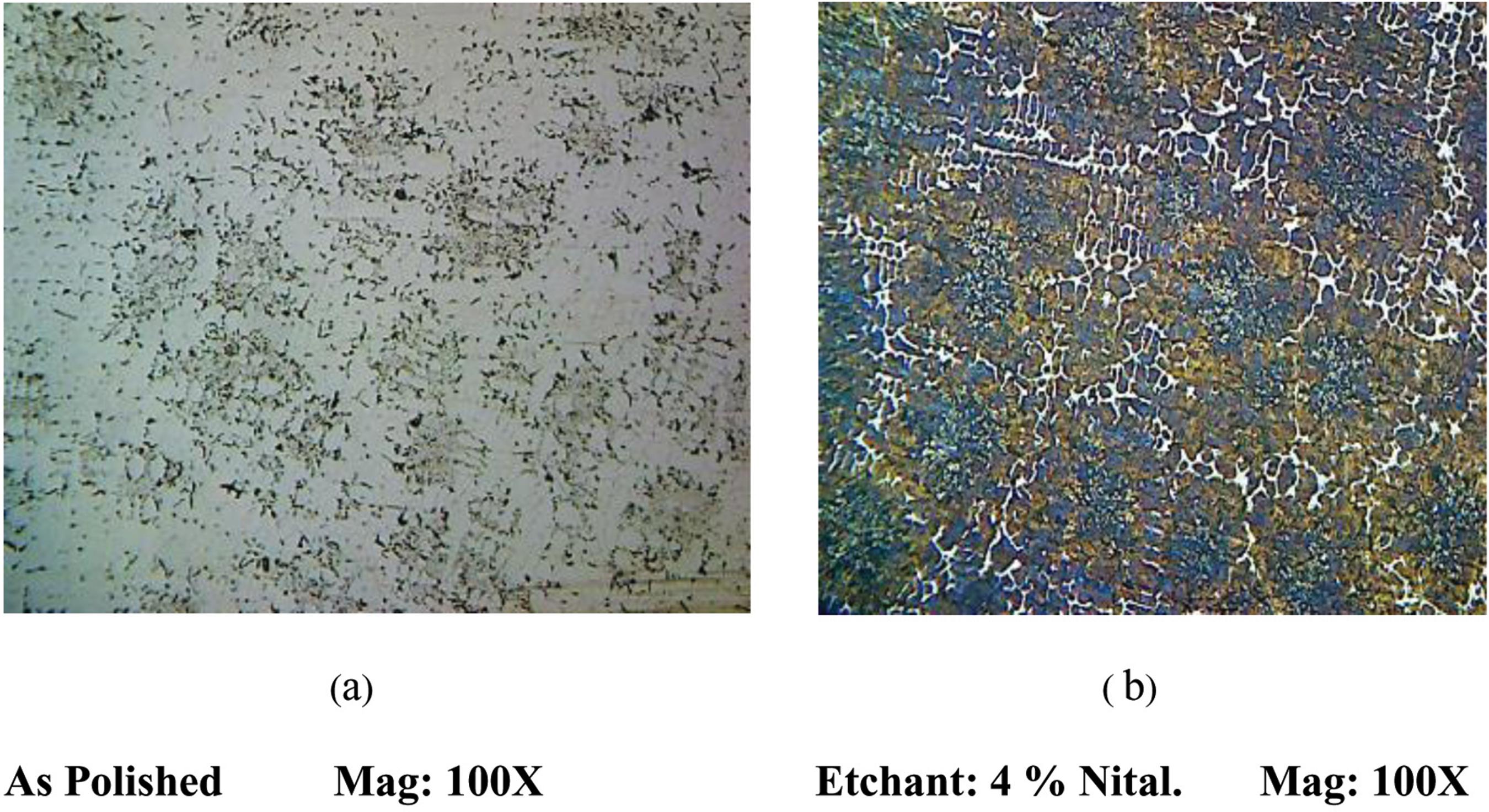
The microstructure of cast iron liner specimen is shown in Figure 4 (a, b).The image was taken by using metallurgical microscope -Metscope-1. In Figure 4 (a) the microstructure of optimized specimen without coating as polished condition and in Figure 4 (b) cleaned specimen are shown. The etchant 4% Nital was used to remove the impurities and rust on the specimen. From figures 4 (a and b) it is clear that the microstructure consist of the graphite flakes of interdentiric segregation orientation of type D. Interdentiric segregation preferred orientation of type E is also observed in a matrix of pearlite. Moreover the phosphorus eutectics are also found in the matrix.
Figure 5 depicts the microstructure of the specimen displayed. The SEM images of the composite coatings reveal that the Al2O3 particles (white) are compactly embedded over the specimen. The rest of the area is occupied by Nickel (Ni). It resembles "regular pyramidal" like structure. Furthermore, Figure 6 shows the EDX analysis of the composites. The analyses were performed on the surface Figure 6 (a). From Figure 6 (b) it is clearly seen that the aluminum (AlK) and oxide (OK) contents are 1.23at% and 5.67at% respectively. The analysis reveals that oxides are the leading elements in the Ni matrix.
Scanning electron microscopy analysis of Ni/nano-Al2O3 composite coatings of optimized cast iron cylinder liner.
3.2 Adhesion strength
If a coating is to fulfill its function of protecting or decorating a substrate, it must serve so its expected service life. The ASTM-D-3359-97 (Method B - Cross-cut Tape Test)1414 ASTM International. ASTM D 3359-97 - Standard Test Methods for Measuring Adhesion by Tape Test. West Conshohocken: ASTM International; 1997. was used to perform the adhesion test over the optimized liner specimen as shown in Figure 7 the classification of 5 result was produced over the specimen. Also the result clearly reveals that the edges of the cuts are completely smooth and none of the squares of the lattice is detached.
3.3 X-Ray Diffraction
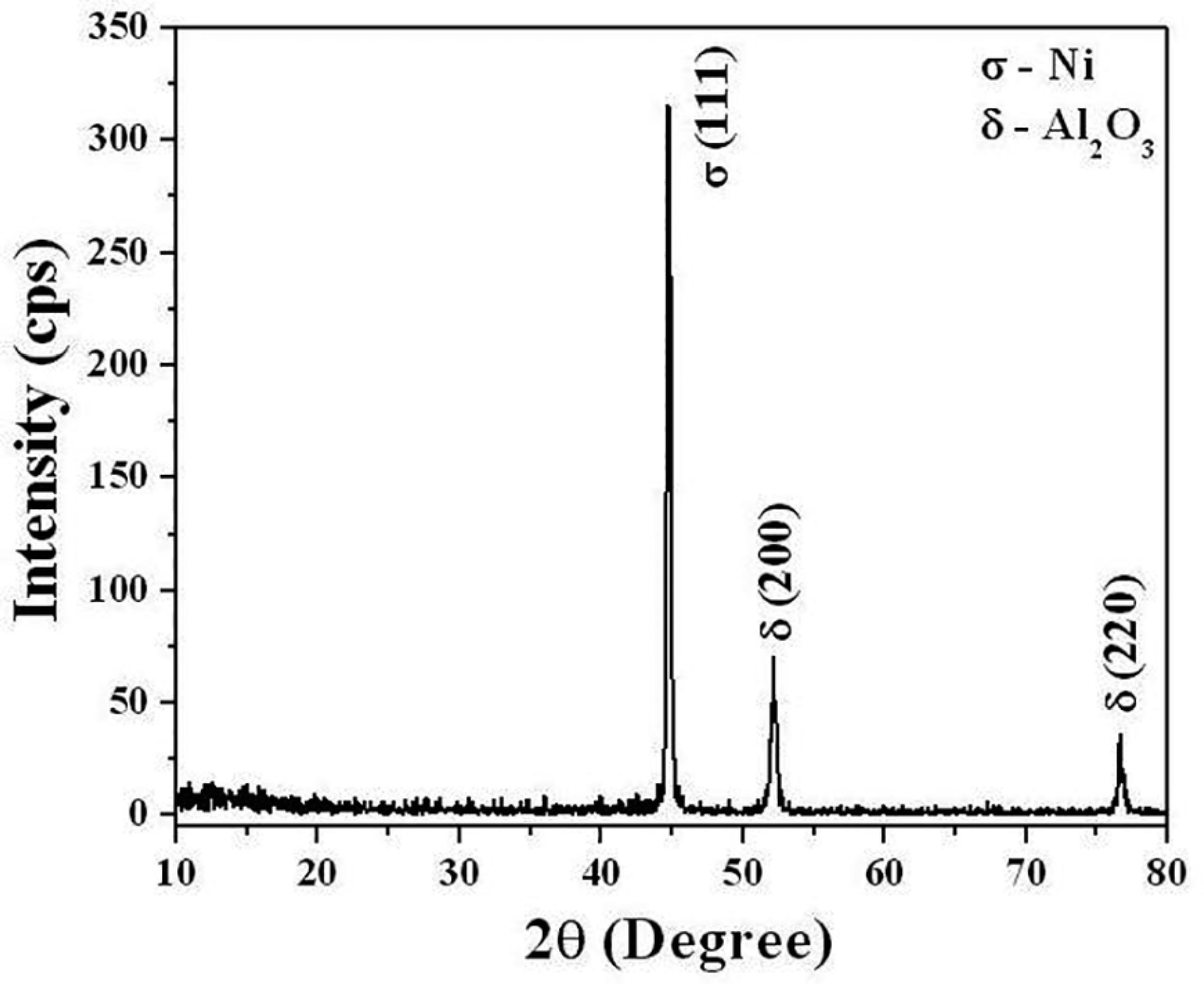
The X-ray diffraction pattern of specimen after subjected to optimized pulse parameter such as frequency 120 Hz, duty cycle 40% and current density 0.7 A/cm2 specimens is shown in Figure 8. The Ni/nano-Al2O3 composites of cast iron liner specimen exhibits face-centered cubic structure (FCC)1515 Chen JS. Characteristic of Ni-Al2O3 Nanocomposition Coatings. Procedia Engineering. 2011;15:4414-4418.
16 Chang LM, An MZ, Shi SY. Microstructure and characterization of Ni-Co/Al2O3 composite coating by pulse reversal electrodeposit. Materials Chemistry and Physics. 2006;100(2-3):395-399.-1717 Chen L, Wang LP, Zeng ZX, Xu T. Influence of pulse frequency on the microstructure and wear resistance of electrodeposited Ni-Al2O3 composite coatings. Surface and Coatings Technology. 2006;201(3-4):599-605.. The Ni-crystal plane is presented in σ (111) peak whereas the Al2O3 are in δ (200) and δ (220). Also Li Chen stated that more crystal growth rate was obtained in pulse electrodeposition and this influenced the preferred orientation. Moreover the Al2O3 (200) plane had more surface energy when compared with Ni (111) plane. Tushar Borkar1818 Borker T, Harimkar SP. Effect of electrodeposition conditions and reinforcement content on microstructure and tribological properties of nickel composite coatings. Surface and Coatings Technology. 2011;205(17-18):4124-4134. has recorded the atomic density of (111) plane is higher than that of (200) plane in FCC crystal structure of nickel and nickel composite coatings. The Ni-Al2O3 composite coatings exhibit strongest peak corresponding to (200) plane at 2Ө = 51.847° indicating development of crystallographic texture. However, as the Al2O3 nanoparticle content in the electrolyte increases up to 20 g/L, the intensity of peak increases. This also corresponds to increasing values of (111) texture coefficient and decreasing values of (200) texture coefficients. The Ni- Al2O3 composite coatings deposited from electrolyte bath with 40 g/L did not follow above trend, and exhibited the intensities of various planes and values of texture coefficients similar to that of pure nickel coatings (oriented through 100] direction). This current Ni/nano-Al2O3 composite coating produced strong preferred orientation with strongest (111) peak at 40 g/L.
3.4 Micro hardness
The Ni/nano-Al2O3 coating does not produce any adverse effect on the base metal of the liner. The optimized microhardness results were calculated from Taguchi's optimization procedure. The specimen attained 1050 HV with the optimized pulse parameters. The hardness was greatly improved by influencing the bath conditions and pulse parameters. The stirring speed is also an important factor to increase the hardness of the specimen1818 Borker T, Harimkar SP. Effect of electrodeposition conditions and reinforcement content on microstructure and tribological properties of nickel composite coatings. Surface and Coatings Technology. 2011;205(17-18):4124-4134.. At 400 rpm stirring speed with different pulse parameters optimum hardness was achieved in this experiment using Taguchi's techniques. The hardness result was significantly identical with plasma sprayed technique which was used to coating over the piston ring/cylinder wall1919 Badarulzaman NA, Purwadaria S, Mohamad AA, Ahamad ZA. The production of nickel-alumina coating via electroplating. Ionics. 2009;15(5):603-607.. Furthermore, microhardness achieved was maximum when compared to low carbon steels and copper1010 Alifkhazraei M, Ahangarani S, Rouhaghdam AS. Effect of the duty cycle of pulsed current on nanocomposite layers formed by pulsed electrodeposition. Rare Metals. 2010;29(2):209-213.,1919 Badarulzaman NA, Purwadaria S, Mohamad AA, Ahamad ZA. The production of nickel-alumina coating via electroplating. Ionics. 2009;15(5):603-607.,2020 Dahm KL, Panagopoulos K, Dearnley PA. The wear response of ceramic matrix nano-composite coatings in simulated piston-ring/cylinder wall test environments. Tribology Series. 2003;41:511-515.
21 Bahroloom ME, Sani R. The influence of pulse parameters on the hardness and wear resistance of nickel-alumina composite coatings. Surface and Coatings Technology. 2005;192(2-3):154-163.
22 Yuan X, Wang T, Sun DB, Yu HY. Influence of pulse parameters on the microstructure and microhardness of nickel electrodeposits. Surface and Coatings Technology. 2008;202(9):1895-1903.
23 Kuo SL. Effect of ion concentration on Ni/Al2O3 composite coatings. Journal of Chinese Institute of Engineers. 2005;28(1):1-8.
24 Chen L, Wang LP, Zeng ZX, Zhang JY. Effect of surfactant on the electrodeposition and wear resistance of Ni-Al2O3 composite coatings. Materials Science Engineering: A. 2006;434(1-2):319-325.
25 Chen JS. Characteristic of Ni-Al2O3 nanocomposition coatings. Procedia Engineering. 2011;15:4414-4418.-2626 Thiemig D, Bund A. Influence of ethanol on the electrocodeposition of Ni/Al2O3 nanocomposite films. Applied Surface Science. 2009;255(7):4164-4170.,3131 ASTM International. ASTM B117-97 - Standard Practice for Operating Salt Spray (Fog) Apparatus. West Conshohocken: ASTM International; 1997..
3.5 Coating Thickness
The coating thickness (8 µm) was measured by ASM standard with magnification 100X2727 Vander Voort GF, ed. ASM Handbook Volume 9: Metallography and Microstructures. Materials Park: ASM International; 2004. on the cross-section of the optimized specimen as shown in Figure 9. The thickness of the coating normally depends on pulse parameters, surface area and amount of nano-Al2O3 particles in the bath2828 Sadiku-Agboola O, Sadiku ER, Ojo OI, Akanji OL, Biotidara OF. Influence of Operation Parameters on Metal Deposition in Bright Nickel-plating Process. Portugaliae Electrochimica Acta. 2011;29(2):91-100.,2929 Feng QY, Li TJ, Zhang ZT, Zhang J, Liu M, Jin JZ. Preparation of nanostructured Ni/Al2O3 composite coatings in high magnetic field. Surface and Coatings Technology. 2007;201(14):6247-6252.. Furthermore Ozkan Sarikaya found that higher hardness, lower porosity and lower surface roughness can be obtained even at lower coating thickness3030 Sarikaya O. Effect of some parameters on microstructure and hardness of alumina coatings prepared by the air plasma spraying process. Surface and Coatings Technology. 2005;190(2-3):388-393.. It is clear that the particular coating thickness was achieved within the given mentioned condition.
Metallurgical Microscope (Metscope-1) image of coating thickness of Ni/nano- Al2O3 composite coatings of cast iron liner specimen.
3.6 Corrosion studies
The corrosion test was conducted over the optimized liner sample. Salt spry test ASTM B 117-07 was used to calculate the corrosion status. The salt spray test has been widely used for process qualification and quality acceptance. It is applicable to metals/alloys and their coatings3131 ASTM International. ASTM B117-97 - Standard Practice for Operating Salt Spray (Fog) Apparatus. West Conshohocken: ASTM International; 1997.. At 70th hr the 'red rust' was appeared over the sample as shown in figure 10. The corrosion status was checked periodically from the beginning At 7th hr, no corrosion appeared over the sample, further at 28, 42, 63, hrs no corrosion for experiment appeared on the sample while at 70th hr the corrosion appeared on the sample. Compared to low carbon steel or mild steel, the cast iron material with less coating thickness takes more time for getting corroded3232 Jegan A, Venkatesan R. Characterization and optimization of pulse electrodeposition of Ni/nano-Al2O3 composite coatings. International Journal of Minerals, Metallurgy and Materials. 2013;20(5):479-485..
3.7 Confirmation test
Confirmation test is final step in the Taguchi's optimization technique. This test was verified the value previously obtained on the experiments show the closer results to that of original values. The optimized pulse parameters such as frequency 120 Hz, duty cycle 40% and current density 0.7 A/cm2 were again used to conduct the confirmation test. The microhardness was 1116.8 HV and the corresponding signal-to-noise ratio (S/N Ratio) was 60.96. From the confirmation test it is observed that the results of hardness and S/N ratios are improved within the confidence level.
4. Conclusions
The electrodeposition of Ni-nano Al2O3 composite coating was effected in a watts bath and applying Taguchi's L27 orthogonal array concept. The following conclusions are made:
-
The electrodeposition of Ni-nano Al2O3 composite coatings produced maximum microhardness (1050HV), uniform microstructure and preferred orientation (111) at the optimum pulse parameters of frequency 120 Hz, duty cycle 40% and current density 0.7 A/cm2. Also the stirring speed 400 rpm and pH 4 were the foremost parameters to increase the hardness of the coatings. Furthermore the specimen exhibited good adhesion strength (5B) and took long time (70h) to get corroded, complying with ASTM standards.
-
Frequency is foremost (48.95%) parameter in increasing the hardness of liner, current density's contribution in increasing the hardness (10.11%) is minimum.
-
The stirring speed 400 rpm is the optimum value for these experiments which is used to increase the hardness of the coatings and achieve more bonding strength between metal and coating.
-
Scanning electron microscope (SEM) clearly depicts, the Ni-nano Al2O3 composites being evenly dispersed over the optimized specimen. The structure of the coating is 'amla seed' like structure. The degree of adhesion of the coatings corresponds to '5B' results of the ASTM D3359-97 standard.
-
Coating thickness (8 µm) was achieved on the optimized specimen. The X-ray diffraction pattern (XRD) shows the orientation of (111) (200) (220) plane which is similar in the available literature.
-
The EDX analysis confirmed that the composites of (AlK) and (OK) were compactly embedded in the Ni matrix. The composites are well adhered on the specimen followed by the ASTM D3359-97 standards.
-
The corrosion status was determined on the optimized specimen. The specimen was withstanding the corrosion resistance up to 70 hrs.
5. References
-
1Karamis MB, Yildizli K, Çakirer H. An evaluation of surface properties and frictional forces generated from Al-Mo-Ni coating on piston ring. Applied Surface Science 2004;230(1-4):191-200.
-
2Johansson S, Frennfelt C, Killinger A, Nilsson PH, Ohlsson R, Rosén BG. Frictional evaluation of thermally sprayed coatings applied on the cylinder liner of a heavy duty diesel engine: Pilot tribometer analysis and full scale engine test. Wear 2011;273(1):82-92.
-
3Johansson S, Nilsson PH, Ohlsson R, Rosén BG. Experimental friction evaluation of cylinder liner/piston ring contact. Wear 2011;271(3-4):625-633.
-
4Kapsiz M, Durat M, Ficici F. Friction and wear studies between cylinder liner and piston ring pair using Taguchi design method. Advances in Engineering Software 2011;42(8):595-603.
-
5Lyubimov VV, Voevodin AA, Yerokhin AL, Timofeev YS, Arkhipov IK. Development and testing of multilayer physically vapour deposited coatings for piston rings. Surface and Coatings Technology 1992;52(2):145-151.
-
6Jung A, Natter H, Hempelmann R, Lach E. Nanocrystalline alumina dispersed in nanocrystalline nickel: enhanced mechanical properties. Journal of Materials Science 2009;44(11):2725-2735.
-
7Dahm KL, Dearnley PA. Novel plasma-based coatings for piston rings. Tribology Series 2002;40:243-246.
-
8Wu G, Li N, Zhou D, Mitsuo K. Electrodeposited Co-Ni-Al2O3 composite coatings. Surface and Coatings Technology 2004;176(2):157-164.
-
9Yang Y, Cheng YF. Fabrication of Ni-Co-SiC composite coatings by pulse electrodeposition - Effects of duty cycle and pulse frequency. Surface and Coatings Technology 2013;216:282-288.
-
10Alifkhazraei M, Ahangarani S, Rouhaghdam AS. Effect of the duty cycle of pulsed current on nanocomposite layers formed by pulsed electrodeposition. Rare Metals 2010;29(2):209-213.
-
11Huang ZJ, Xiong DS. MoS2 coated with Al2O3 for Ni-MoS2/al2O3 composite coatings by pulsed electrodepostion. Surface and Coatings Technology 2008;212(14):3208-3214.
-
12Kang J, Hadfield M. Parameter optimization by Taguchi Methods for finishing advanced ceramic balls using a novel eccentric lapping machine. Proceedings of the Institution of Mechanical Engineers, Part B: Journal of Engineering Manufacture 2001;215(1):69-78.
-
13Rose PJ. Taguchi Techniques for Quality Engineering New Delhi: Tata McGraw-Hill; 2005.
-
14ASTM International. ASTM D 3359-97 - Standard Test Methods for Measuring Adhesion by Tape Test West Conshohocken: ASTM International; 1997.
-
15Chen JS. Characteristic of Ni-Al2O3 Nanocomposition Coatings. Procedia Engineering 2011;15:4414-4418.
-
16Chang LM, An MZ, Shi SY. Microstructure and characterization of Ni-Co/Al2O3 composite coating by pulse reversal electrodeposit. Materials Chemistry and Physics 2006;100(2-3):395-399.
-
17Chen L, Wang LP, Zeng ZX, Xu T. Influence of pulse frequency on the microstructure and wear resistance of electrodeposited Ni-Al2O3 composite coatings. Surface and Coatings Technology 2006;201(3-4):599-605.
-
18Borker T, Harimkar SP. Effect of electrodeposition conditions and reinforcement content on microstructure and tribological properties of nickel composite coatings. Surface and Coatings Technology 2011;205(17-18):4124-4134.
-
19Badarulzaman NA, Purwadaria S, Mohamad AA, Ahamad ZA. The production of nickel-alumina coating via electroplating. Ionics 2009;15(5):603-607.
-
20Dahm KL, Panagopoulos K, Dearnley PA. The wear response of ceramic matrix nano-composite coatings in simulated piston-ring/cylinder wall test environments. Tribology Series 2003;41:511-515.
-
21Bahroloom ME, Sani R. The influence of pulse parameters on the hardness and wear resistance of nickel-alumina composite coatings. Surface and Coatings Technology 2005;192(2-3):154-163.
-
22Yuan X, Wang T, Sun DB, Yu HY. Influence of pulse parameters on the microstructure and microhardness of nickel electrodeposits. Surface and Coatings Technology 2008;202(9):1895-1903.
-
23Kuo SL. Effect of ion concentration on Ni/Al2O3 composite coatings. Journal of Chinese Institute of Engineers 2005;28(1):1-8.
-
24Chen L, Wang LP, Zeng ZX, Zhang JY. Effect of surfactant on the electrodeposition and wear resistance of Ni-Al2O3 composite coatings. Materials Science Engineering: A 2006;434(1-2):319-325.
-
25Chen JS. Characteristic of Ni-Al2O3 nanocomposition coatings. Procedia Engineering 2011;15:4414-4418.
-
26Thiemig D, Bund A. Influence of ethanol on the electrocodeposition of Ni/Al2O3 nanocomposite films. Applied Surface Science 2009;255(7):4164-4170.
-
27Vander Voort GF, ed. ASM Handbook Volume 9: Metallography and Microstructures Materials Park: ASM International; 2004.
-
28Sadiku-Agboola O, Sadiku ER, Ojo OI, Akanji OL, Biotidara OF. Influence of Operation Parameters on Metal Deposition in Bright Nickel-plating Process. Portugaliae Electrochimica Acta 2011;29(2):91-100.
-
29Feng QY, Li TJ, Zhang ZT, Zhang J, Liu M, Jin JZ. Preparation of nanostructured Ni/Al2O3 composite coatings in high magnetic field. Surface and Coatings Technology 2007;201(14):6247-6252.
-
30Sarikaya O. Effect of some parameters on microstructure and hardness of alumina coatings prepared by the air plasma spraying process. Surface and Coatings Technology 2005;190(2-3):388-393.
-
31ASTM International. ASTM B117-97 - Standard Practice for Operating Salt Spray (Fog) Apparatus West Conshohocken: ASTM International; 1997.
-
32Jegan A, Venkatesan R. Characterization and optimization of pulse electrodeposition of Ni/nano-Al2O3 composite coatings. International Journal of Minerals, Metallurgy and Materials 2013;20(5):479-485.
Publication Dates
-
Publication in this collection
26 Mar 2018 -
Date of issue
May-Jun 2018
History
-
Received
24 Jan 2018 -
Accepted
26 Feb 2018