Abstract
Stress corrosion cracking (SCC) of UNS S31603 austenitic stainless steel (ASS), UNS S32205 duplex stainless steel (DSS) and UNS S32750 super duplex stainless steel (SDSS) was investigated. SCC tests were carried out at 110 ºC for 500 h under drops of synthetic seawater (DET, drop evaporation test). Two loading conditions were investigated: 50 % and 100 % of the experimental yield strength of each steel. DSS and SDSS specimens showed no susceptibility to SCC under loading of 50 % of their yield strength, contrary to ASS, but all steels fractured at the highest load. SCC nucleated under the salt deposit formed on the surface of all specimens. SCC propagation was mainly transgranular, but SCC propagation of DSS also featured crack ramification in the austenite phase. In addition, SDSS also presented crack propagation along the ferrite/austenite interfaces. Transgranular cleavage fracture was also observed in all fractured specimens, but DSS also presented ferrite/austenite interfacial brittle fracture, while SDSS also featured intergranular brittle fracture.
Keywords:
Stress Corrosion Cracking; Drop Evaporation Test; Stainless Steels
1. Introduction
In Brazil, ninety-five percent of the petroleum is extracted from offshore wells, requiring a large range of engineering components and materials, which should present high corrosion resistance to marine environments. In this sense, ASS, DSS and SDSS are usually selected for the manufacturing of offshore pressure vessels11 Agência Nacional do Petróleo. Anuário Estatístico Brasileiro do Petróleo, Gás Natural e Biocombustíveis. Rio de Janeiro: Ministério de Minas e Energia; 2016., due to their high corrosion resistance and good mechanical properties. These offshore components are usually submitted to service conditions combining tensile stress and chloride environments, which may induce their premature failure by stress corrosion cracking (SCC), even under tensile values below the yield strength22 Cramer SD, Covino BS Jr., eds. ASM Handbook Volume 13A. Corrosion: Fundamentals, Testing, and Protection. Material Park: ASM International; 2003.
3 Kain V. Stress corrosion cracking (SCC) in stainless steels. In: Raja VS, Shoji T, eds. Stress Corrosion Cracking: Theory and Practice. Sawston: Woodhead Publishing; 2011. p. 199-244. DOI: https://doi.org/10.1533/9780857093769.3.199
https://doi.org/10.1533/9780857093769.3....
-44 Raja VS, Shoji T, eds. Stress Corrosion Cracking - Theory and Practice. Sawston: Woodhead Publishing; 2011.. A comparison of the general properties and characteristics of the ASS and DSS and SDSS is shown in Table 1. Although DSS and SDSS are more expensive than ASS, their values of fracture toughness, yield strength and pitting resistance equivalent number (PREN) are comparatively much higher55 Granta Design. CES Edupack 2017: General information, Database level 3. Oxford: Granta Design; 2017.. Despite their wide and growing usage of DSS and SDSS components, they might be subjected to various types of mechanical and environmentally induced failures during their life cycle, especially when these components are exposed to temperatures in the range of 300 ºC to 900 ºC, which might promote the precipitation of stable and deleterious phases55 Granta Design. CES Edupack 2017: General information, Database level 3. Oxford: Granta Design; 2017.
6 Gunn RN, ed. Duplex Stainless Steels: Microstructure, Properties and Applications. Cambridge: Woodhead Publishing; 1997.
7 Alvarez-Armas I, Degallaix-Moreuil S, eds. Duplex Stainless Steels. 1st ed. London: John Wiley & Sons; 2009.-88 Azevedo CRF, Pereira HB, Wolynec S, Padilha AF. An overview of the recurrent failures of duplex stainless steels. Engineering Failure Analysis. 2019;97:161-188..
General properties of UNS S31603, UNS S32205 and UNS S32760 stainless steels55 Granta Design. CES Edupack 2017: General information, Database level 3. Oxford: Granta Design; 2017..
Stainless steels (SSs) may suffer SCC when three critical conditions occur simultaneously: microstructural susceptibility, corrosive environment and tensile stress. The weight of each one of these critical parameters is different for each class of SS44 Raja VS, Shoji T, eds. Stress Corrosion Cracking - Theory and Practice. Sawston: Woodhead Publishing; 2011.,66 Gunn RN, ed. Duplex Stainless Steels: Microstructure, Properties and Applications. Cambridge: Woodhead Publishing; 1997.
7 Alvarez-Armas I, Degallaix-Moreuil S, eds. Duplex Stainless Steels. 1st ed. London: John Wiley & Sons; 2009.
8 Azevedo CRF, Pereira HB, Wolynec S, Padilha AF. An overview of the recurrent failures of duplex stainless steels. Engineering Failure Analysis. 2019;97:161-188.-99 Shoji T, Lu Z, Peng Q. Factors affecting stress corrosion cracking (SCC) and fundamental mechanistic understanding of stainless steels. In: Raja VS, Shoji T, eds. Stress Corrosion Cracking: Theory and Practice. Sawston: Woodhead Publishing; 2011. p. 245-272. DOI: https://doi.org/10.1533/9780857093769.3.245
https://doi.org/10.1533/9780857093769.3....
. Environments containing chloride ions, however, are especially harmful to the strength of the passive film of SSs, promoting the pitting corrosion and increasing the susceptibility to SCC in these steels11 Agência Nacional do Petróleo. Anuário Estatístico Brasileiro do Petróleo, Gás Natural e Biocombustíveis. Rio de Janeiro: Ministério de Minas e Energia; 2016.
2 Cramer SD, Covino BS Jr., eds. ASM Handbook Volume 13A. Corrosion: Fundamentals, Testing, and Protection. Material Park: ASM International; 2003.-33 Kain V. Stress corrosion cracking (SCC) in stainless steels. In: Raja VS, Shoji T, eds. Stress Corrosion Cracking: Theory and Practice. Sawston: Woodhead Publishing; 2011. p. 199-244. DOI: https://doi.org/10.1533/9780857093769.3.199
https://doi.org/10.1533/9780857093769.3....
,55 Granta Design. CES Edupack 2017: General information, Database level 3. Oxford: Granta Design; 2017.
6 Gunn RN, ed. Duplex Stainless Steels: Microstructure, Properties and Applications. Cambridge: Woodhead Publishing; 1997.-77 Alvarez-Armas I, Degallaix-Moreuil S, eds. Duplex Stainless Steels. 1st ed. London: John Wiley & Sons; 2009.. Additionally, the presence of other cations, such as magnesium and calcium, might further increase the aggressivity of the chloride environments and the susceptibility of SSs to SCC1010 Cottis RA, Newman RC. Stress Corrosion Cracking Resistance of Duplex Stainless Steels. London: Offshore Safety Division; 1993.. Actually, the SCC of SSs might occur even in caustic solutions, when the surfaces of the component present regions of pitting or crevice corrosion1111 Panossian Z, Pecequilo CV, Brunelli RA, Flor JP, Pimenta G de S. Avaliação da susceptibilidade à corrosão em frestas de ligas de alta resistência à corrosão por meio de ensaios eletroquímicos. Corrosão e Proteção. 2012;43:26-32.-1212 Wolynec S. Técnicas eletroquímicas em Corrosão. São Paulo: EDUSP; 2003.. SCC might also happen when the anodic reaction takes place underneath an occluded region of the surface, causing a significant decrease of the solution’s pH1111 Panossian Z, Pecequilo CV, Brunelli RA, Flor JP, Pimenta G de S. Avaliação da susceptibilidade à corrosão em frestas de ligas de alta resistência à corrosão por meio de ensaios eletroquímicos. Corrosão e Proteção. 2012;43:26-32.-1212 Wolynec S. Técnicas eletroquímicas em Corrosão. São Paulo: EDUSP; 2003.. Although pitting and crevice corrosions are not prerequisites for the nucleation of SCC in SSs, they can act as stress raisers and solution acidifiers, promoting, therefore, the nucleation of SCC22 Cramer SD, Covino BS Jr., eds. ASM Handbook Volume 13A. Corrosion: Fundamentals, Testing, and Protection. Material Park: ASM International; 2003.,55 Granta Design. CES Edupack 2017: General information, Database level 3. Oxford: Granta Design; 2017.
6 Gunn RN, ed. Duplex Stainless Steels: Microstructure, Properties and Applications. Cambridge: Woodhead Publishing; 1997.-77 Alvarez-Armas I, Degallaix-Moreuil S, eds. Duplex Stainless Steels. 1st ed. London: John Wiley & Sons; 2009.,1010 Cottis RA, Newman RC. Stress Corrosion Cracking Resistance of Duplex Stainless Steels. London: Offshore Safety Division; 1993.
11 Panossian Z, Pecequilo CV, Brunelli RA, Flor JP, Pimenta G de S. Avaliação da susceptibilidade à corrosão em frestas de ligas de alta resistência à corrosão por meio de ensaios eletroquímicos. Corrosão e Proteção. 2012;43:26-32.
12 Wolynec S. Técnicas eletroquímicas em Corrosão. São Paulo: EDUSP; 2003.
13 Gulbrandsen S. Overview of Stress Corrosion Cracking in Stainless Steel: Electronic Enclosures in Extreme Environmental Conditions. College Park: DfR Solutions; 2005.-1414 Wolynec S. Corrosão sob tensão: Análise de Fraturas. São Paulo: Associação Brasileira de Metais; 2000..
The stable crack propagation of ASS, DSS and SDSS usually presents a ductile behavior under non aggressive environments, but the action of SCC promotes a brittle behaviour in these steels, leading to the formation of intergranular or cleavage-like transgranular brittle fractures1515 Magnin T, Chambreuil A, Chateau JR. Stress corrosion cracking mechanisms in ductile FCC materials. International Journal of Fracture. 1996;79(2):147-63.. It is interesting to observe that the exposure to a corrosive environment might decrease the fracture toughness of ASS from KIC equals to 72 MPa.m(1/2) to KISCC (acidic solution) equals to 53 MPa.m(1/2)55 Granta Design. CES Edupack 2017: General information, Database level 3. Oxford: Granta Design; 2017.
6 Gunn RN, ed. Duplex Stainless Steels: Microstructure, Properties and Applications. Cambridge: Woodhead Publishing; 1997.
7 Alvarez-Armas I, Degallaix-Moreuil S, eds. Duplex Stainless Steels. 1st ed. London: John Wiley & Sons; 2009.-88 Azevedo CRF, Pereira HB, Wolynec S, Padilha AF. An overview of the recurrent failures of duplex stainless steels. Engineering Failure Analysis. 2019;97:161-188.. There are at least four atomic-level mechanisms to explain the stable brittle crack propagation of metals and alloys caused by SCC44 Raja VS, Shoji T, eds. Stress Corrosion Cracking - Theory and Practice. Sawston: Woodhead Publishing; 2011.,55 Granta Design. CES Edupack 2017: General information, Database level 3. Oxford: Granta Design; 2017.
6 Gunn RN, ed. Duplex Stainless Steels: Microstructure, Properties and Applications. Cambridge: Woodhead Publishing; 1997.
7 Alvarez-Armas I, Degallaix-Moreuil S, eds. Duplex Stainless Steels. 1st ed. London: John Wiley & Sons; 2009.
8 Azevedo CRF, Pereira HB, Wolynec S, Padilha AF. An overview of the recurrent failures of duplex stainless steels. Engineering Failure Analysis. 2019;97:161-188.
9 Shoji T, Lu Z, Peng Q. Factors affecting stress corrosion cracking (SCC) and fundamental mechanistic understanding of stainless steels. In: Raja VS, Shoji T, eds. Stress Corrosion Cracking: Theory and Practice. Sawston: Woodhead Publishing; 2011. p. 245-272. DOI: https://doi.org/10.1533/9780857093769.3.245
https://doi.org/10.1533/9780857093769.3....
-1010 Cottis RA, Newman RC. Stress Corrosion Cracking Resistance of Duplex Stainless Steels. London: Offshore Safety Division; 1993.,1515 Magnin T, Chambreuil A, Chateau JR. Stress corrosion cracking mechanisms in ductile FCC materials. International Journal of Fracture. 1996;79(2):147-63.
16 Ferreira PJ, Robertson IM, Birnbaum HK. Hydrogen effects on the interaction between dislocations. Acta Materialia. 1998;46(5):1749-1757.
17 Lépinoux J, Magnin T. Stress corrosion microcleavage in a ductile f.c.c. alloy. Materials Science and Engineering: A. 1993;164(1-2):266-269.
18 Magnin T, Chieragatti R, Oltra R. Mechanism of brittle fracture in a ductile 316 alloy during stress corrosion. Acta Metallurgica et Materialia. 1990;38(7):1313-1319.
19 Flanagan WF, Bastias P, Lichter BD. Theory of transgranular stress-corrosion cracking. Acta Metallurgica et Materialia. 1991;39(4):695-705.
20 Qiao L, Mao X. Thermodynamic analysis on the role of hydrogen in anodic stress-corrosion cracking. Acta Metallurgica et Materialia. 1995;43(11):4001-4006.
21 Sieradzki K, Newman RC. Brittle behavior of ductile metals during stress-corrosion cracking. Philosophical Magazine A. 1985;51(1):95-132.-2222 Bhattacharya A, Singh PM. Electrochemical behaviour of duplex stainless steels in caustic environment. Corrosion Science. 2011;53(1):71-81.:
-
The tensile decohesion of the atomic bounds of the metallic material ahead of the crack tip (cleavage) is promoted by the adsorption of ions of the corrosive solution on the metallic surfaces near the crack tip. This adsorption is followed by surface diffusion of these ions into the region ahead of the crack tip, causing local embrittlement due to the decohesion of the atomic bounds (see Figure 1)44 Raja VS, Shoji T, eds. Stress Corrosion Cracking - Theory and Practice. Sawston: Woodhead Publishing; 2011.,55 Granta Design. CES Edupack 2017: General information, Database level 3. Oxford: Granta Design; 2017.
6 Gunn RN, ed. Duplex Stainless Steels: Microstructure, Properties and Applications. Cambridge: Woodhead Publishing; 1997.-77 Alvarez-Armas I, Degallaix-Moreuil S, eds. Duplex Stainless Steels. 1st ed. London: John Wiley & Sons; 2009.,2323 Rehbinder PA, Shchukin ED. Surface phenomena in solids during deformation and fracture processes. Progress in Surface Science. 1972;3(Pt 2): 97-104, IN1-IN2, 105-124, IN3-IN4, 125-142, IN5-IN6, 143-146, IN7-IN8, 147-188.-2424 Coleman EG, Weinstein D, Rostoker W. On a surface energy mechanism for stress-corrosion cracking. Acta Metallurgica. 1961;9(5):491-496.; -
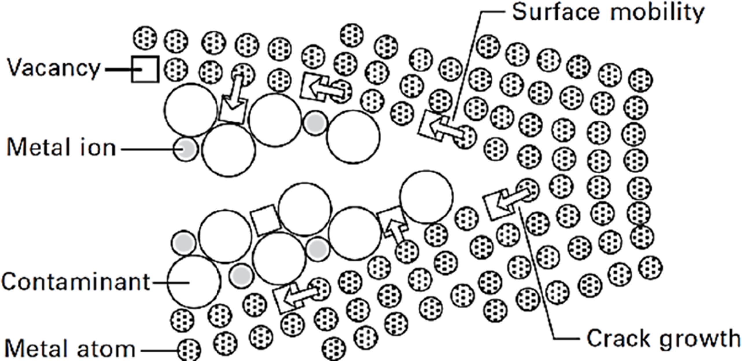
The creation of vacancies on the metallic surfaces near the crack tip is caused by the removal of the elements of the crystal lattice by the corrosive solution. These vacancies preferentially diffuse towards the region ahead of the crack tip due to the presence of a stress gradient. The metallic ion surface mobility is promoted by the presence of contaminants in the corrosive solution. The stable step-like brittle propagation of the crack takes place when these vacancies reach the crack tip (see Figure 2)55 Granta Design. CES Edupack 2017: General information, Database level 3. Oxford: Granta Design; 2017.
6 Gunn RN, ed. Duplex Stainless Steels: Microstructure, Properties and Applications. Cambridge: Woodhead Publishing; 1997.-77 Alvarez-Armas I, Degallaix-Moreuil S, eds. Duplex Stainless Steels. 1st ed. London: John Wiley & Sons; 2009.,2525 Galvele JR. Surface mobility mechanism of stress-corrosion cracking. Corrosion Science. 1993;35(1-4):419-434.-2626 Galvele JR. Application of the surface-mobility stress corrosion cracking mechanism to nuclear materials. Journal of Nuclear Materials. 1996;229:139-148.;Figure 2
SCC mechanism: cracking propagation of the crack tip due to the surface mobility induced by corrosive environment44 Raja VS, Shoji T, eds. Stress Corrosion Cracking - Theory and Practice. Sawston: Woodhead Publishing; 2011.,2525 Galvele JR. Surface mobility mechanism of stress-corrosion cracking. Corrosion Science. 1993;35(1-4):419-434..
-
The formation of a brittle surface film on the metallic surfaces near the crack tip locally reduces the fracture toughness, promoting the stable step-like brittle propagation of the crack. According to this model, the formation of the brittle film is induced by the environment, which controls the kinetics of the stable crack propagation. In this sense, the next step of the stable brittle propagation of the crack will proceed when another layer of brittle film is formed ahead of the crack tip (see Figure 3)44 Raja VS, Shoji T, eds. Stress Corrosion Cracking - Theory and Practice. Sawston: Woodhead Publishing; 2011.,55 Granta Design. CES Edupack 2017: General information, Database level 3. Oxford: Granta Design; 2017.
6 Gunn RN, ed. Duplex Stainless Steels: Microstructure, Properties and Applications. Cambridge: Woodhead Publishing; 1997.-77 Alvarez-Armas I, Degallaix-Moreuil S, eds. Duplex Stainless Steels. 1st ed. London: John Wiley & Sons; 2009.,2727 Saito M, Smith GS, Newman RC. Testing the film-induced cleavage model of stress-corrosion cracking. Corrosion Science. 1993;35(1-4): 411-413, 415-417.-2828 Ricker RE, Fink JL, Escalante E. Evidence of film-induced cleavage by electrodeposited rhodium. Corrosion Deformations Interactions. In: Magnin T, Gras JM, eds. Corrosion Deformations Interactions. Les Ulis: Editions de Physique (EDP Sciences); 1993.;Figure 3
SCC mechanism: formation of a brittle surface film at the crack tip2828 Ricker RE, Fink JL, Escalante E. Evidence of film-induced cleavage by electrodeposited rhodium. Corrosion Deformations Interactions. In: Magnin T, Gras JM, eds. Corrosion Deformations Interactions. Les Ulis: Editions de Physique (EDP Sciences); 1993..
-
The shear strain in the region located ahead of the crack tip is promoted by the adsorption of atomic hydrogen on the surfaces of the crack (see Figure 4). These hydrogen atoms diffuse into the FCC lattice, preferentially into the region located ahead of the crack-tip. The presence of interstitial hydrogen atoms in this region locally increase the plasticity of the metal. In the case of FCC iron, the hydrogen atom (atomic radius equals to 0.48 Å) preferentially occupies its octahedral interstitial sites (size of approximately 0.52 Å) without introducing any lattice elastic strain. The presence of interstitial hydrogen in this lattice decreases its shear modulus and the repulsion forces between edge dislocations, consequently reducing the distance between these dislocations and increasing both the density of the dislocation pile-up and the stress field ahead of the leading dislocation. This stress field will promote the nucleation of a secondary crack at the dislocation slip obstacle (such as a grain-boundary) and this crack will propagate towards the crack tip by a brittle mechanism due to the high dislocation density between the obstacle and the tip. Additionally, this same stress field will activate the slip systems of the adjacent grains, repeating the process of nucleation and brittle propagation of secondary cracks (see Figure 4)55 Granta Design. CES Edupack 2017: General information, Database level 3. Oxford: Granta Design; 2017.
6 Gunn RN, ed. Duplex Stainless Steels: Microstructure, Properties and Applications. Cambridge: Woodhead Publishing; 1997.-77 Alvarez-Armas I, Degallaix-Moreuil S, eds. Duplex Stainless Steels. 1st ed. London: John Wiley & Sons; 2009.,1515 Magnin T, Chambreuil A, Chateau JR. Stress corrosion cracking mechanisms in ductile FCC materials. International Journal of Fracture. 1996;79(2):147-63.
16 Ferreira PJ, Robertson IM, Birnbaum HK. Hydrogen effects on the interaction between dislocations. Acta Materialia. 1998;46(5):1749-1757.
17 Lépinoux J, Magnin T. Stress corrosion microcleavage in a ductile f.c.c. alloy. Materials Science and Engineering: A. 1993;164(1-2):266-269.
18 Magnin T, Chieragatti R, Oltra R. Mechanism of brittle fracture in a ductile 316 alloy during stress corrosion. Acta Metallurgica et Materialia. 1990;38(7):1313-1319.
19 Flanagan WF, Bastias P, Lichter BD. Theory of transgranular stress-corrosion cracking. Acta Metallurgica et Materialia. 1991;39(4):695-705.-2020 Qiao L, Mao X. Thermodynamic analysis on the role of hydrogen in anodic stress-corrosion cracking. Acta Metallurgica et Materialia. 1995;43(11):4001-4006..Figure 4
SCC mechanism in FCC metals: hydrogen induced plasticity, promoting denser dislocation pile-up and higher stress field, causing the nucleation and brittle propagation of secondary cracks from the obstacle towards the tip of the primary crack. The stress field will also activate the slip system of the adjacent grain, repeating the process of nucleation and brittle propagation of secondary cracks44 Raja VS, Shoji T, eds. Stress Corrosion Cracking - Theory and Practice. Sawston: Woodhead Publishing; 2011..
Although, there are several mechanisms to explain the brittle crack propagation during SCC, none of them allows a straightforward approach for the microstructural design of SCC resistant SSs. Therefore, the experimental determination of the critical stress for the activation of the SCC during service conditions is an important technique to investigate the SCC susceptibility of metals and alloys. SCC tests usually use smooth or pre-cracked specimens under static or dynamic mechanical load exposed to a particular environment (corrosive solution and temperature). In some cases, a pre-loaded specimen is immersed in a standard solution with controlled temperature, while in other SCC tests a standard solution drips on pre-loaded specimens with controlled temperature55 Granta Design. CES Edupack 2017: General information, Database level 3. Oxford: Granta Design; 2017.
6 Gunn RN, ed. Duplex Stainless Steels: Microstructure, Properties and Applications. Cambridge: Woodhead Publishing; 1997.-77 Alvarez-Armas I, Degallaix-Moreuil S, eds. Duplex Stainless Steels. 1st ed. London: John Wiley & Sons; 2009.,2929 Andersen H, Arnvig P, Wasielewska W, Wegrelius L, Wolfe C. SCC of Stainless Steel under Evaporative Conditions. In: Corrosion 98; 1998 Mar 22-27; San Diego, CA, USA.
30 Hinds G, Turnbull A. Stress Corrosion Cracking of Duplex Stainless Steel under Simulated Evaporation Conditions. In: Corrosion 2007; 2007 Mar 11-15; Nashville, TN, USA.
31 Turnbull A, Zhou S, Nicholson P, Hinds G. Chemistry of concentrated salts formed by evaporation of seawater on duplex stainless steel. Corrosion. 2008;64(4):325-333.-3232 Steinsmo U, Drugli JM. Assessment of susceptibility to chloride stress corrosion cracking of highly alloyed stainless steels. Part 1: Drop evaporation test method. In: Corrosion 1997; 1997 Mar 9-14; New Orleans, LA USA.. The drop evaporation test (DET), for instance, simulates the external environment of offshore components by dripping synthetic seawater on pre-loaded specimens with controlled temperature. This method is performed using different combinations of tensile stress, temperature and standard solutions to determine the critical parameters for the onset of SCC3030 Hinds G, Turnbull A. Stress Corrosion Cracking of Duplex Stainless Steel under Simulated Evaporation Conditions. In: Corrosion 2007; 2007 Mar 11-15; Nashville, TN, USA.. Seawater DET at temperatures above 105 ºC forms a saline deposit on the surface of the specimen, which act as a barrier to the diffusion of oxygen, locally promoting the crevice corrosion and SCC nucleation and growth underneath the deposit3131 Turnbull A, Zhou S, Nicholson P, Hinds G. Chemistry of concentrated salts formed by evaporation of seawater on duplex stainless steel. Corrosion. 2008;64(4):325-333.-3232 Steinsmo U, Drugli JM. Assessment of susceptibility to chloride stress corrosion cracking of highly alloyed stainless steels. Part 1: Drop evaporation test method. In: Corrosion 1997; 1997 Mar 9-14; New Orleans, LA USA..
This paper will investigate and compare the SCC susceptibility of UNS S31603 ASS, UNS S32205 DSS and UNS S32750 SDSS at 110 ºC for 500 h under drops of synthetic see water. These conditions are similar to those used in offshore pressure vessels and one of the objective of this paper is to verify which of these materials presented lower SCC susceptibility in accordance with DET.
2. Materials and Methods
The specimens used for the drop evaporation tests were machined from 12.7 mm thickness plates and their microstructures are shown in Figure 5-a to 5-c. Figure 5-a features the microstructure of the UNS S31603 ASS specimen, showing equiaxial austenitic grains with small amount of ferrite strips, following the rolling direction of the plate. The center of this Figure shows an unetched region, due to the work hardening of the ASS plate. Figures 5-b and 5-c feature the microstructures of UNS S32205 DSS and UNS S32750 SDSS, respectively, revealing a lamellar microstructure composed of ferrite (dark region) and austenite (white region) phases with elongated grains, indicating the rolling direction of the plate (KOH electrolytic attack was used to identify the ferrite phase).
Microstructure of the investigated SSs: (a) UNS S31603 ASS; (b) UNS S32205 DSS; (c) UNS S32750 SDSS. Optical microscope. Electrolytic etching: oxalic acid for ASS and KOH for DSS and ASS.
The chemical compositions of the SS used in the present investigation are shown in Table 2. Carbon and sulfur contents were measured by the combustion method using a LECO analyzer (model CS844)3333 ASTM International. ASTM E1019 - Standard Test Methods for Determination of Carbon, Sulfur, Nitrogen, and Oxygen in Steel, Iron, Nickel, and Cobalt Alloys by Various Combustion and Fusion Techniques. West Conshohocken: ASTM International; 2011. and the remaining elements were measured by wavelength dispersive X-ray fluorescence spectrometry (Rigaku WDXRF, model RIX 3000)3434 ASTM International. ASTM E572 - Standard Test Method for Analysis of Stainless and Alloy Steels by Wavelength Dispersive X-Ray Fluorescence Title Spectrometry. West Conshohocken: ASTM International; 2013.. The chemical compositions of the SSs are in accordance with the requirements of ASTM A240 standard3535 ASTM International. ASTM A240-04 - Standard Specification for Chromium and Chromium-Nickel Stainless Steel Plate, Sheet, and Strip for Pressure Vessels and for General Applications. West Conshohocken: ASTM International; 2004..
Chemical composition of UNS S31603 ASS, UNS S32205 DSS and UNS S32750 DSS * * Sulphur contents are not show in the table, but they were in accordance with the requirements of ASTM A24035. .
Tensile mechanical tests were performed using a 10 t MM-004 tensile testing machine, according to the ABNT NBR ISO 6892 standard3636 Associação Brasileira de Normas Técnicas (ABNT). ABNT NBR ISO 6892: Ensaio de Tração - Método de ensaio à temperatura ambiente (Parte 1). Rio de Janeiro: ABNT; 2009. and using cylindrical specimens with diameter of 5 mm. The results are shown in Table 3, indicating that the tensile properties of the SSs are in accordance with the requirements of the ASTM A240 standard3535 ASTM International. ASTM A240-04 - Standard Specification for Chromium and Chromium-Nickel Stainless Steel Plate, Sheet, and Strip for Pressure Vessels and for General Applications. West Conshohocken: ASTM International; 2004.. Table 3 also features the investigated tensile stresses during DET for each SS.
Mechanical properties of UNS S31603 ASS, UNS S32205 DSS and UNS S32750 SDSS at room temperature and the values of maximum tensile stress used for DET for conditions (a) and (b).
DET specimens (10 mm x 25 mm x 178 mm) were machined along the perpendicular plane of the rolling direction. A schematic representation of the mechanical loading assembly using “four point bending” is shown in Figure 6 along with the identification of its geometrical parameters3737 ASTM International. ASTM G39-99 - Standard Practice for Preparation and Use of Bent-Beam Stress-Corrosion Test. West Conshohocken: ASTM International; 2011.. The roughness of the top surface of the specimens (exposed to the dripping during the DET) was measured by a KOSAKA rugosimeter to guarantee that the roughness values (Ra) of the specimens were lower than 0.7 µm3737 ASTM International. ASTM G39-99 - Standard Practice for Preparation and Use of Bent-Beam Stress-Corrosion Test. West Conshohocken: ASTM International; 2011.. The maximum tensile stress on the surface of the specimens after bending was calculated by Equation I3737 ASTM International. ASTM G39-99 - Standard Practice for Preparation and Use of Bent-Beam Stress-Corrosion Test. West Conshohocken: ASTM International; 2011.. Two mechanical loading conditions were investigated: a) maximum tensile stress equal to 50 % of the experimental yield strength at room temperature (see Table 3); b) maximum tensile stress equal to 100 % of the experimental yield strength at room temperature (see Table 3).
Where σ is the tensile stress upon the maximum bending strain (MPa); E is the elastic modulus (MPa); t is the thickness of the specimen (mm); y is the bending height between the superior loading point and the center of the specimen (mm); H is the distance between the upper loading points (mm); and is the distance between the upper and A lower loading points (mm).
Schematic representation of the apparatus for mechanical loading (four-point bending) of the specimen and their geometrical parameters3737 ASTM International. ASTM G39-99 - Standard Practice for Preparation and Use of Bent-Beam Stress-Corrosion Test. West Conshohocken: ASTM International; 2011..
Pre-loaded specimens were placed in chambers with heating resistances controlled by a proportional-integral-derivative controller (PID, NOVUS® model N1030). Synthetic seawater used was prepared according to the ASTM D1141 and ASTM D1193 standards, featuring a pH equals to 8.2 and chemical composition described in Table 4 3838 ASTM International. ASTM D1193-06 - Standard Specification for Reagent Water. West Conshohocken: ASTM International; 2006.-3939 ASTM International. ASTM D1141-98e1 - Standard Practice for the Preparation of Substitute Ocean Water. West Conshohocken: ASTM International; 1999..
Saline concentration of synthetic sea water according to ASTM D11413838 ASTM International. ASTM D1193-06 - Standard Specification for Reagent Water. West Conshohocken: ASTM International; 2006.-3939 ASTM International. ASTM D1141-98e1 - Standard Practice for the Preparation of Substitute Ocean Water. West Conshohocken: ASTM International; 1999..
DET was carried at 110 ºC for 500 h and the dripping rate of synthetic sea water was kept equal to (10 ± 1) drops per minute. After DET4040 International Organization for Standardization (ISO). ISO 15324 - Corrosion of metals and alloys - Evaluation of stress corrosion cracking by the drop evaporation test. Geneva: ISO; 2000., the microstructures of the DETed SSs were analyzed using the same etching procedures as described previously. Optical microscopy using an Olympus® microscope model BX51M and a Leica® stereomicroscope model M205 C were used during the metallographic and macrofractographic examination. Microfractographic examination of the cracked/ fractured specimens used a scanning electron microscope (SEM FEI Quanta 400) with acceleration voltage of 20 kV and current of 1 nA. FEI Quanta 3D FEG dual beam microscope was also used as focused ion beam (FIB) microscopy in order to characterize the microstructure under the surface of SCC (cross-sectional examination).
3. Results
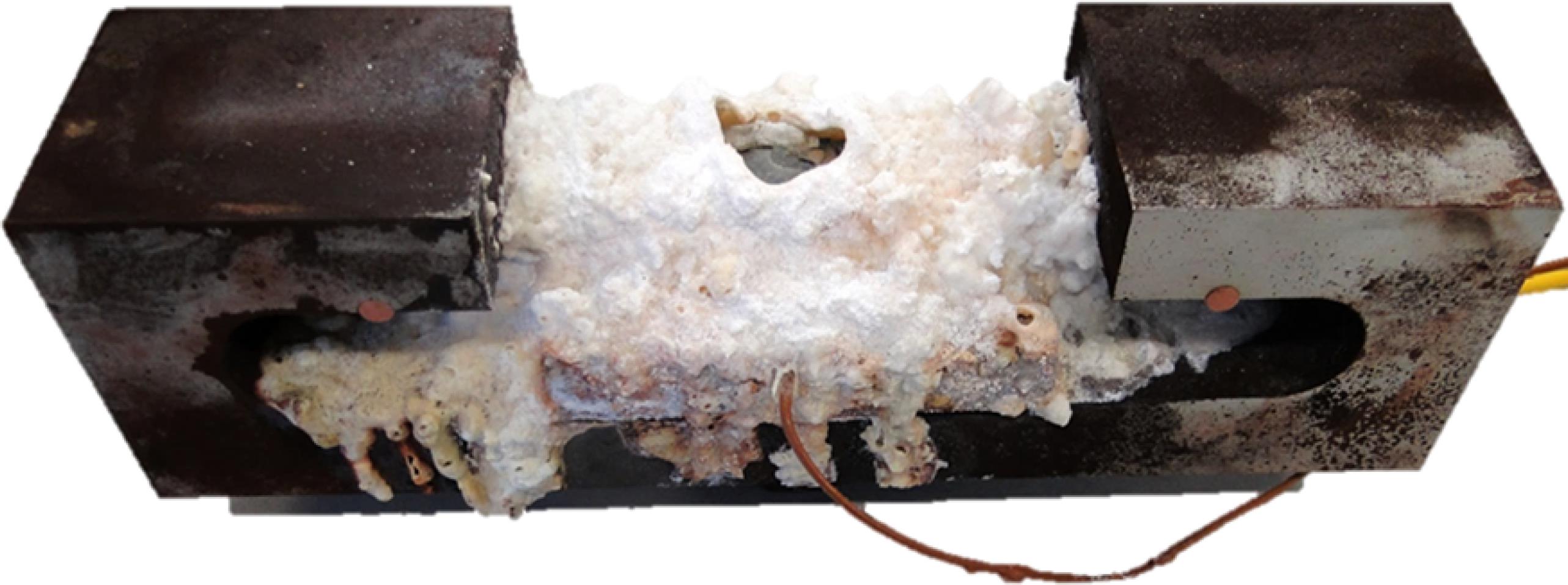
A salt deposit in the form of a “volcano” was formed on the surfaces of all DETed specimens. The surfaces on the dripping region, however, did not feature the presence of any deposit (see Figure 7).
General aspect of the salt deposit formed on the surface of all specimens after DET at 110 ºC for 500 h.
Figures 8-a to 8-c show the general aspects of the DETed specimens after rinsing with water. Figure 8-a shows an ASS specimen tested at 50 % of its yield stress (139 MPa) which exhibits some dark oxidized regions on the surface of the specimen without any evidence of cracking during the visual examination. Additionally, its dripping zone does not show any signs of oxidation. DSS specimen tested at 50 % of its yield stress (236 MPa) and SDSS specimen tested at 50 % of its yield stress (295 MPa) did not show evidences of cracking during the visual examination. However, all specimens tested under tensile loading of 100 % of their yield strength presented cracking or fracture during visual inspection. The general view of a DSS specimen after testing at 100 % of its yield stress (473 MPa) is shown in Figure 8-b, where a 45° crack is observed (see yellow arrow). A SDSS specimen after testing at 100 % of its yield stress (589 MPa) is observed in Figure 8-c, where multiple cracks can be observed (see yellow arrow). Both crack nucleation sites coincide with the position of the salt layer. Additionally, the dripping zones located in the center of the specimens do not show any signs oxidation. A closer examination of the dark oxidized regions of all the tested specimens, located away from the salt layer, showed corrosion products, such as pitting and localized-corrosion, indicating that temperature of 110 ºC is above the critical limit for the pitting corrosion.
Visual inspections of specimens tested at 110 ºC for 500 hours after the cleaning. (a) UNS S31603 ASS tested at 50 % of the yield stress (139 MPa); (b) UNS S32205 DSS tested at 100 % of the yield stress (473 MPa); and (c) UNS S32750 SDSS tested at 100 % of the yield stress (589 MPa). Visual inspection.
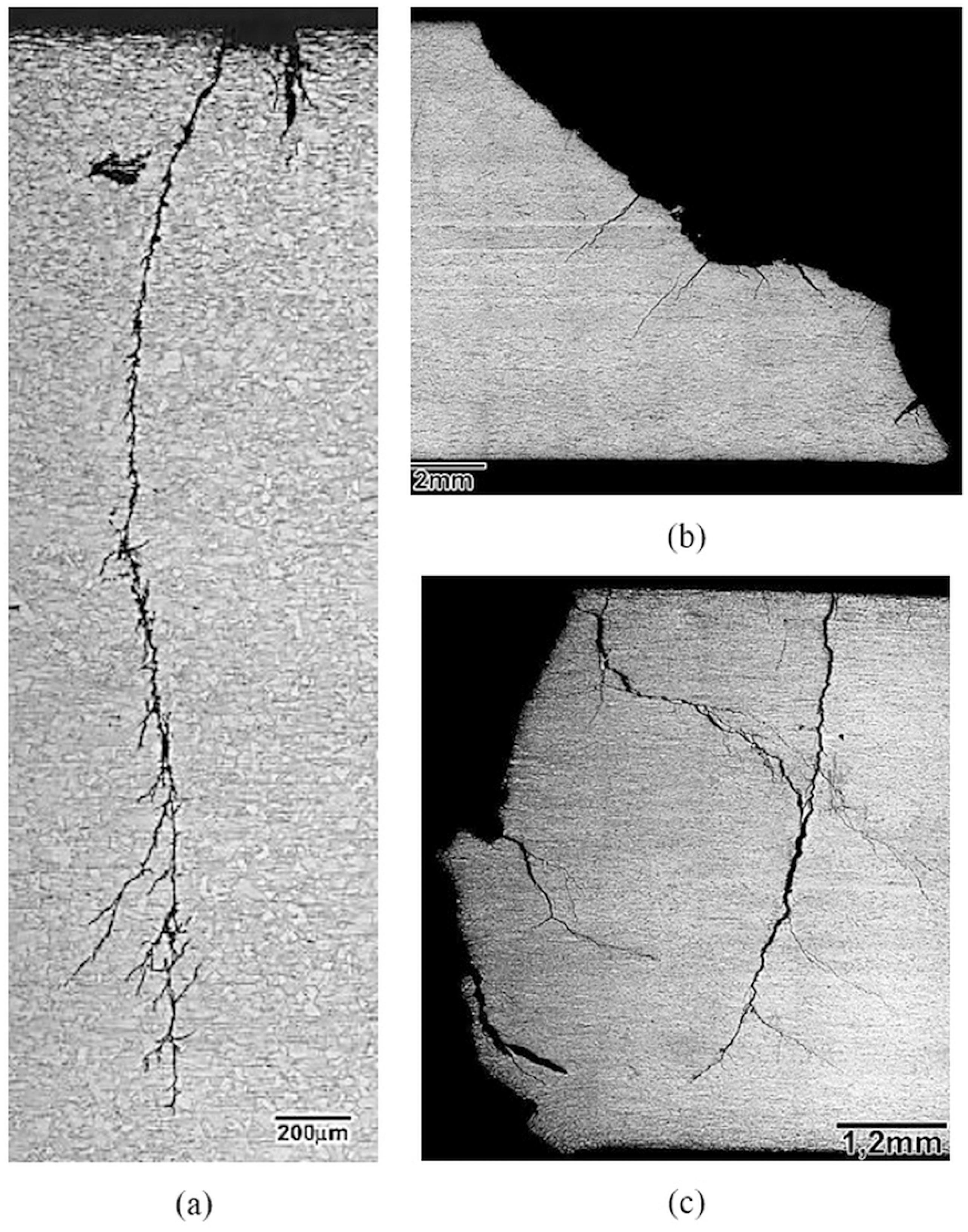
Contrary to the visual examination, the metallographic examination of an ASS specimen tested at 50 % of its yield strength (139 MPa) showed ramified cracking, which was nucleated in a corrosion pit under the salt deposit (see Figure 9-a). Furthermore, the metallographic examination of this sample indicated multiple cracks and the longest one showed a depth of approximately of 3 mm. The cracks were transgranular and featured intense ramification after a crack depth of 600 µm and the primary crack preferentially propagated normal to the surface of the specimen. Metallographic examination of a DSS specimen tested at 100 % of its yield strength (473 MPa) presented a 45º crack propagation followed by a horizontal crack deflection near the plate’s center, where the alloy exhibited a more prominent work-hardened microstructure (see Figure 9-b). The crack propagation of the DSS was comparatively less ramified than the ASS (see Figure 9-a), but their secondary cracks were comparatively much deeper (maximum depth of 2500 µm). Metallographic examination of a SDSS specimen tested at 100 % of its yield strength (589 MPa), see Figure 9-c, exhibited multiple nucleation sites and, comparatively, more intense crack ramification. The secondary cracks were comparatively deeper than the DSS (maximum depth of approximately 4000 µm).
Metallographic examination of the crack propagation, cross section after DET at 110 °C. (a) UNS S31603 ASS tested at 50 % of the yield stress (139 MPa); (b) UNS S32205 DSS tested at 100 % of the yield stress (473 MPa); (c) UNS S32750 SDSS tested at 100 % of the yield stress (589 MPa). Optical microscope.
Figure 10-a presents the crack propagation of an ASS specimen tested at 100 % of its yield stress (278 MPa), presenting transgranular propagation and crack deflection at grain boundaries. Figure 10-b presents the crack propagation of a DSS specimen tested at 100 % of its yield stress (473 MPa), showing transgranular propagation and preferential crack ramification inside the austenite phase. Figure 10-c presents the crack propagation of a SDSS specimen tested at 100 % of its yield stress (589 MPa), showing transgranular and interfacial propagation and preferential crack ramification inside the austenite phase. The cracks of the DSS and SDSS propagated preferentially at 45º of the rolling direction and parallel to the maximum shear stress of the bended specimens, while the crack of ASS propagated normal to the rolling direction.
Propagation of the SCC along the microstructure after DET at 110 °C. (a) UNS S31603 ASS tested at 100 % of the yield stress (278 MPa); (b) UNS S32205 DSS tested at 100 % of the yield stress (473 MPa); (c) UNS S32750 SDSS tested at 100 % of the yield stress (589 MPa). Optical microscope.
Figures 11-a to 11-c show the microfractographic examination of the exposed crack surfaces. The fracture of an ASS specimen tested at 100 % of its yield stress, 278 MPa, is shown in Figure 11-a, which exhibits a brittle fracture with stretch marks and few secondary cracks, typical of transgranular cleavage. The fracture of a DSS specimen tested at 100 % of its yield stress (473 MPa) is shown Figure 11-b, which features cleavage fracture and intense presence of secondary cracks and interfacial brittle fracture (see flat facets), resulting in transgranular and intergranular brittle fracture. The fracture of a SDSS specimen tested at 100 % of its yield stress (589 MPa) is shown Figure 11-c, which features transgranular cleavage with more intense secondary cracking. Additionally, the presence of interfacial and grain boundary brittle fractures (see comparatively smaller flat facets) can also be observed.
Microfractographic examination of the exposed surface of the cracks after DET at 110 °C. (a) UNS S31603 ASS tested at 100 % of the yield stress (278 MPa); (b) UNS S32205 DSS tested at 100 % of the yield stress (473 MPa); (c) UNS S32750 SDSS tested at 100 % of the yield stress (589 MPa). SEM.
Figures 12-a to 12-c display the images obtained by the FIB cross section examination near the SCC surfaces. Figure 12-a shows the microstructure under a SCC surface (ASS specimen tested at 100 % of its yield stress - 278 MPa), presenting angular deflection of the SCC at a grain boundary (see solid arrow) and a small area of intense plastic deformation near the SCC surface (see dotted arrow). Figure 12-b shows the microstructure under the SCC surface (DSS specimen tested at 100 % of its yield stress - 473 MPa), exhibiting various secondary cracks with transgranular and interfacial propagation and crack ramification (see solid arrows). Additionally, a small area of intense plastic deformation is also observed near the SCC surface (see dotted arrow). Figure 12-c presents the microstructure under the SCC surface (SDSS specimen tested at 100 % of its yield stress - 589 MPa), showing that interfaces and grain boundaries promote a step-like SCC propagation. Additionally, few transgranular secondary cracks are observed.
Microestrutural characterization below the exposed SCC surface after DET at 110 °C. (a) UNS S31603 ASS tested at 100 % of the yield stress (278 MPa); (b) UNS S32205 DSS tested at 100 % of the yield stress (473 MPa); (c) UNS S32750 SDSS tested at 100 % of the yield stress (589 MPa). FIB.
4. Discussion
The formation of a thick salt deposit associated with the SCC in all DSS and SDSS specimens tested at 110 ºC (see Figure 7) is in accordance with previous results of Turnbull and Hinds3030 Hinds G, Turnbull A. Stress Corrosion Cracking of Duplex Stainless Steel under Simulated Evaporation Conditions. In: Corrosion 2007; 2007 Mar 11-15; Nashville, TN, USA.-3131 Turnbull A, Zhou S, Nicholson P, Hinds G. Chemistry of concentrated salts formed by evaporation of seawater on duplex stainless steel. Corrosion. 2008;64(4):325-333. and Steinsmo and Drugli 3232 Steinsmo U, Drugli JM. Assessment of susceptibility to chloride stress corrosion cracking of highly alloyed stainless steels. Part 1: Drop evaporation test method. In: Corrosion 1997; 1997 Mar 9-14; New Orleans, LA USA.. Turnbull and Hinds3131 Turnbull A, Zhou S, Nicholson P, Hinds G. Chemistry of concentrated salts formed by evaporation of seawater on duplex stainless steel. Corrosion. 2008;64(4):325-333., for instance, investigated the susceptibility of 22 Cr and 25 Cr DSSs to SCC under evaporative seawater conditions using a modified DET. The use of flat specimens allowed the seawater to accumulate on the dripping zone, producing a hollow-damp salt deposit, whose edges advance along the gauge length during the test (see Figure 13).
Scheme of the salt deposit formed on all the DETed specimens tested at 110 ºC for 500 h. The SCCs were nucleated under the salt deposit, approximately 22 mm away from the center of the dripping region, by crevice corrosion4141 Pereira HB, Azevedo CRF. Can the drop evaporation test evaluate the stress corrosion cracking susceptibility of the welded joints of duplex and super duplex stainless steels? Engineering Failure Analysis. 2019. In Press..
In another investigation, the authors4141 Pereira HB, Azevedo CRF. Can the drop evaporation test evaluate the stress corrosion cracking susceptibility of the welded joints of duplex and super duplex stainless steels? Engineering Failure Analysis. 2019. In Press. showed that during DET at 110 ºC, the solution found at the center of the specimens (dripping zone) presented a pH value of around 11, much higher than the original pH of the synthetic seawater solution (pH equal to 8.2), indicating the occurrence of a cathodic reaction in this region (see Figure 14-a). Additionally, the temperature of the DET specimens in the vicinities of the dripping zone was at least 10 ºC lower than the remaining regions, due to the cooling action of the synthetic solution drops (see Figure 14-b). The anodic reaction took place under the salt deposit, locally promoting the crevice and pitting corrosion, followed by SCC nucleation and growth. Steinsmo and Drugli3232 Steinsmo U, Drugli JM. Assessment of susceptibility to chloride stress corrosion cracking of highly alloyed stainless steels. Part 1: Drop evaporation test method. In: Corrosion 1997; 1997 Mar 9-14; New Orleans, LA USA. also observed the formation of massive salt deposits and steep temperature gradients (sometimes up to 15 ºC) along DET specimens. According to these authors3232 Steinsmo U, Drugli JM. Assessment of susceptibility to chloride stress corrosion cracking of highly alloyed stainless steels. Part 1: Drop evaporation test method. In: Corrosion 1997; 1997 Mar 9-14; New Orleans, LA USA., SCC preferentially nucleated in areas showing the highest temperatures, which were located far from center of the dripping zone.
(a) Scheme showing the relative position of the cathodic (dripping zone) and the anodic reactions (under the salt deposit); (b) Temperature distribution along the upper surface of the specimen at 110 ºC. The temperature in the center of the dripping region is roughly 10 ºC lower than the testing temperature. Points located at -25 mm and + 25 mm represent the usual SCC nucleation sites4141 Pereira HB, Azevedo CRF. Can the drop evaporation test evaluate the stress corrosion cracking susceptibility of the welded joints of duplex and super duplex stainless steels? Engineering Failure Analysis. 2019. In Press..
The formation of salt deposit on the samples tested at 110 ºC promoted the crevice corrosion of the plate under the deposit (see Figure 7), followed by the preferential attack (ferrite phase and austenite/ferrite interfaces), the formation of a corrosion pit and, finally, the nucleation and growth of SCC, confirming previous results4141 Pereira HB, Azevedo CRF. Can the drop evaporation test evaluate the stress corrosion cracking susceptibility of the welded joints of duplex and super duplex stainless steels? Engineering Failure Analysis. 2019. In Press.,4242 Pereira HB. Corrosão sob tensão de junta soldada de aço inoxidável duplex: Ensaio de flexão em quatro pontos sob gotejamento de solução de água do mar sintética. [Dissertation]. São Paulo: Universidade de São Paulo; 2018.. The salt deposit was identified by Pereira4242 Pereira HB. Corrosão sob tensão de junta soldada de aço inoxidável duplex: Ensaio de flexão em quatro pontos sob gotejamento de solução de água do mar sintética. [Dissertation]. São Paulo: Universidade de São Paulo; 2018. as a mixture of CaSO4; NaCl, Mg(OH)2 MgCl2, which is hygroscopic, creating a corrosive wet interface between the salt deposit and the surface of the specimen. The observation of occasional corrosion and pitting beneath the salt deposit is in accordance with the observation of previous work3131 Turnbull A, Zhou S, Nicholson P, Hinds G. Chemistry of concentrated salts formed by evaporation of seawater on duplex stainless steel. Corrosion. 2008;64(4):325-333., indicating that the combination of aggressive solution under the salt deposit (with pH values between zero and one) and microplastic deformation was responsible for SCC of the SSs tested above 105 ºC3131 Turnbull A, Zhou S, Nicholson P, Hinds G. Chemistry of concentrated salts formed by evaporation of seawater on duplex stainless steel. Corrosion. 2008;64(4):325-333. (this temperature coincides with the evaporation temperature of the seawater3131 Turnbull A, Zhou S, Nicholson P, Hinds G. Chemistry of concentrated salts formed by evaporation of seawater on duplex stainless steel. Corrosion. 2008;64(4):325-333.). FIB results (see Figures 12-a and 12-b) indicated the presence of small regions of plastic deformation below the SCC surfaces of ASS and DSS specimens, as suggested by previous investigation on SCC of DSSs3131 Turnbull A, Zhou S, Nicholson P, Hinds G. Chemistry of concentrated salts formed by evaporation of seawater on duplex stainless steel. Corrosion. 2008;64(4):325-333..
ASS samples showed multiple nucleation sites even for DET at 110 ºC and loading of 50 % of its yield stress (139 MPa), see Figure 9-a, indicating that its SCC threshold stress at 110 ºC is above 139 MPa. DSS and SDSS samples presented fractured DET specimens at 110 ºC and loading of 100 % of the yield strength (473 MPa and 589 MPa, respectively), see Figures 9-b and 9-c, showing that their threshold stress for SCC is between 50 % and 100 % of their yield strength (see Table 3).
Additionally, ASS specimens tested at 100 % of the yield stress (278 MPa) showed transgranular crack propagation and crack deflection at grain boundaries, while the crack propagation of UNS S32205 DSS specimens tested at 100 % of yield stress (473 MPa) also revealed the preferential crack ramification inside the austenite phase. SDSS specimens tested at 100 % of the yield stress (589 MPa) featured additional ferrite/austenite interfacial crack propagation (see Figures 10-a to 10-c). The cracks of the DSS and SDSS preferentially propagated at 45º of the rolling direction (parallel to the maximum shear stress of the bended specimens), while ASS cracking was perpendicular to the tensile stress. Microfractographic examination of ASS specimens tested at 110 ºC with 100 % of the yield stress (278 MPa) exhibited transgranular brittle fracture, while DSS specimens tested at 110 ºC with 100 % of the yield stress (473 MPa) also featured austenite/ferrite interfacial brittle fracture. SDSS specimens tested at 100 % of the yield stress (589 MPa) also featured intergranular brittle fracture (see Figures 11-a to 11-c).
DETed ASS specimen tested at 100 % of its yield stress (279 MPa) presented SCC deflection at the grain boundaries and plastic deformation of the austenite grains near the SCC surface (see Figure 12-a). DETed DSS specimen tested at 100 % of its yield stress (473 MPa) additionally exhibited ramified secondary cracks with transgranular and interfacial propagation (see Figure 12-b). SDSS specimen tested at 100 % of its yield stress (589 MPa) showed the influence of interfaces and grain boundaries on the crack deflection, promoting a step-like crack propagation (see Figure 12-c). These observations are in agreement with previous results3131 Turnbull A, Zhou S, Nicholson P, Hinds G. Chemistry of concentrated salts formed by evaporation of seawater on duplex stainless steel. Corrosion. 2008;64(4):325-333.. Finally, the SDSS showed the lowest SCC susceptibly at 110 °C in seawater, followed by DSS and finally by ASS specimens.
5. Conclusions
The results of SCC sweater DET of ASS (UNS S31603), DSS (UNS S32205) and SDSS (UNS S32750) performed at 50 % and 100 % of the yield stress at 110 ºC for 500 hours indicated that:
-
SCC presented preferential nucleation sites under the salt deposit. The formation of the salt deposit at 110 ºC promoted the anodic reaction, resulting in the formation of an aggressive wet interface between the deposit and the surface of the specimens, leading to crevice corrosion, preferential attack of the ferrite phase, pit formation and SCC nucleation and growth.
-
The tensile stress of 139 MPa was above the SCC threshold stress for the ASS at 110 °C. The tensile stress values of 473 MPa (DSS) and 589 MPa (SDSS) were above the SCC threshold stresses at 110 °C;
-
SCC of DSS and SDSS specimens preferentially propagated at 45º of the rolling direction (parallel to the maximum shear stress), while the SCC of ASS propagated normal to the rolling direction.
-
SCC propagation of ASS and DSS was mainly transgranularly. DSS specimen also showed preferential crack ramification inside the austenite phase, while SDSS specimen additionally presented crack propagation along the ferrite/austenite interfaces.
-
Transgranular cleavage microfractography was observed for all SSs tested at 110 ºC. DSS additionally presented areas of flat facets, indicating ferrite/austenite interfacial brittle fracture, while SDSS also featured intergranular brittle fracture.
-
SDSS speciments showed the lowest SCC susceptibly during DET at 110 °C in seawater, followed by DSS and finally by ASS specimens.
6. Acknowledgments
The authors would like to thank Petrobras for financing the Project nº1260/14: “Corrosão sob tensão de aços inoxidáveis austenítico, dúplex e super dúplex: Estudo dos limites de temperatura para ocorrência de corrosão sob tensão (CST) em juntas soldadas em atmosfera marinha sob evaporação” and the kind collaboration and the support of Dr. T. Y. Fukuhara, Dr. H. L. Ito and Eng. M. F. Moreira from Instituto de Pesquisas Tecnológicas do Estado de São Paulo (IPT) and Dr. A.C.P. Rodrigues from Escola Politécnica da Universidade de São Paulo. Finally, Prof. C. R. F. Azevedo would like to thank the support of the Brazilian National Council for Scientific and Technological Development (CNPq) for the research grant (Process n° 302077/2016-2).
7. References
-
1Agência Nacional do Petróleo. Anuário Estatístico Brasileiro do Petróleo, Gás Natural e Biocombustíveis Rio de Janeiro: Ministério de Minas e Energia; 2016.
-
2Cramer SD, Covino BS Jr., eds. ASM Handbook Volume 13A. Corrosion: Fundamentals, Testing, and Protection Material Park: ASM International; 2003.
-
3Kain V. Stress corrosion cracking (SCC) in stainless steels In: Raja VS, Shoji T, eds. Stress Corrosion Cracking: Theory and Practice. Sawston: Woodhead Publishing; 2011. p. 199-244. DOI: https://doi.org/10.1533/9780857093769.3.199
» https://doi.org/10.1533/9780857093769.3.199 -
4Raja VS, Shoji T, eds. Stress Corrosion Cracking - Theory and Practice Sawston: Woodhead Publishing; 2011.
-
5Granta Design. CES Edupack 2017: General information, Database level 3 Oxford: Granta Design; 2017.
-
6Gunn RN, ed. Duplex Stainless Steels: Microstructure, Properties and Applications Cambridge: Woodhead Publishing; 1997.
-
7Alvarez-Armas I, Degallaix-Moreuil S, eds. Duplex Stainless Steels 1st ed. London: John Wiley & Sons; 2009.
-
8Azevedo CRF, Pereira HB, Wolynec S, Padilha AF. An overview of the recurrent failures of duplex stainless steels. Engineering Failure Analysis 2019;97:161-188.
-
9Shoji T, Lu Z, Peng Q. Factors affecting stress corrosion cracking (SCC) and fundamental mechanistic understanding of stainless steels. In: Raja VS, Shoji T, eds. Stress Corrosion Cracking: Theory and Practice Sawston: Woodhead Publishing; 2011. p. 245-272. DOI: https://doi.org/10.1533/9780857093769.3.245
» https://doi.org/10.1533/9780857093769.3.245 -
10Cottis RA, Newman RC. Stress Corrosion Cracking Resistance of Duplex Stainless Steels London: Offshore Safety Division; 1993.
-
11Panossian Z, Pecequilo CV, Brunelli RA, Flor JP, Pimenta G de S. Avaliação da susceptibilidade à corrosão em frestas de ligas de alta resistência à corrosão por meio de ensaios eletroquímicos. Corrosão e Proteção 2012;43:26-32.
-
12Wolynec S. Técnicas eletroquímicas em Corrosão São Paulo: EDUSP; 2003.
-
13Gulbrandsen S. Overview of Stress Corrosion Cracking in Stainless Steel: Electronic Enclosures in Extreme Environmental Conditions College Park: DfR Solutions; 2005.
-
14Wolynec S. Corrosão sob tensão: Análise de Fraturas São Paulo: Associação Brasileira de Metais; 2000.
-
15Magnin T, Chambreuil A, Chateau JR. Stress corrosion cracking mechanisms in ductile FCC materials. International Journal of Fracture 1996;79(2):147-63.
-
16Ferreira PJ, Robertson IM, Birnbaum HK. Hydrogen effects on the interaction between dislocations. Acta Materialia 1998;46(5):1749-1757.
-
17Lépinoux J, Magnin T. Stress corrosion microcleavage in a ductile f.c.c. alloy. Materials Science and Engineering: A 1993;164(1-2):266-269.
-
18Magnin T, Chieragatti R, Oltra R. Mechanism of brittle fracture in a ductile 316 alloy during stress corrosion. Acta Metallurgica et Materialia 1990;38(7):1313-1319.
-
19Flanagan WF, Bastias P, Lichter BD. Theory of transgranular stress-corrosion cracking. Acta Metallurgica et Materialia 1991;39(4):695-705.
-
20Qiao L, Mao X. Thermodynamic analysis on the role of hydrogen in anodic stress-corrosion cracking. Acta Metallurgica et Materialia 1995;43(11):4001-4006.
-
21Sieradzki K, Newman RC. Brittle behavior of ductile metals during stress-corrosion cracking. Philosophical Magazine A 1985;51(1):95-132.
-
22Bhattacharya A, Singh PM. Electrochemical behaviour of duplex stainless steels in caustic environment. Corrosion Science 2011;53(1):71-81.
-
23Rehbinder PA, Shchukin ED. Surface phenomena in solids during deformation and fracture processes. Progress in Surface Science 1972;3(Pt 2): 97-104, IN1-IN2, 105-124, IN3-IN4, 125-142, IN5-IN6, 143-146, IN7-IN8, 147-188.
-
24Coleman EG, Weinstein D, Rostoker W. On a surface energy mechanism for stress-corrosion cracking. Acta Metallurgica 1961;9(5):491-496.
-
25Galvele JR. Surface mobility mechanism of stress-corrosion cracking. Corrosion Science 1993;35(1-4):419-434.
-
26Galvele JR. Application of the surface-mobility stress corrosion cracking mechanism to nuclear materials. Journal of Nuclear Materials 1996;229:139-148.
-
27Saito M, Smith GS, Newman RC. Testing the film-induced cleavage model of stress-corrosion cracking. Corrosion Science 1993;35(1-4): 411-413, 415-417.
-
28Ricker RE, Fink JL, Escalante E. Evidence of film-induced cleavage by electrodeposited rhodium. Corrosion Deformations Interactions. In: Magnin T, Gras JM, eds. Corrosion Deformations Interactions Les Ulis: Editions de Physique (EDP Sciences); 1993.
-
29Andersen H, Arnvig P, Wasielewska W, Wegrelius L, Wolfe C. SCC of Stainless Steel under Evaporative Conditions In: Corrosion 98; 1998 Mar 22-27; San Diego, CA, USA.
-
30Hinds G, Turnbull A. Stress Corrosion Cracking of Duplex Stainless Steel under Simulated Evaporation Conditions In: Corrosion 2007; 2007 Mar 11-15; Nashville, TN, USA.
-
31Turnbull A, Zhou S, Nicholson P, Hinds G. Chemistry of concentrated salts formed by evaporation of seawater on duplex stainless steel. Corrosion 2008;64(4):325-333.
-
32Steinsmo U, Drugli JM. Assessment of susceptibility to chloride stress corrosion cracking of highly alloyed stainless steels Part 1: Drop evaporation test method. In: Corrosion 1997; 1997 Mar 9-14; New Orleans, LA USA.
-
33ASTM International. ASTM E1019 - Standard Test Methods for Determination of Carbon, Sulfur, Nitrogen, and Oxygen in Steel, Iron, Nickel, and Cobalt Alloys by Various Combustion and Fusion Techniques West Conshohocken: ASTM International; 2011.
-
34ASTM International. ASTM E572 - Standard Test Method for Analysis of Stainless and Alloy Steels by Wavelength Dispersive X-Ray Fluorescence Title Spectrometry West Conshohocken: ASTM International; 2013.
-
35ASTM International. ASTM A240-04 - Standard Specification for Chromium and Chromium-Nickel Stainless Steel Plate, Sheet, and Strip for Pressure Vessels and for General Applications West Conshohocken: ASTM International; 2004.
-
36Associação Brasileira de Normas Técnicas (ABNT). ABNT NBR ISO 6892: Ensaio de Tração - Método de ensaio à temperatura ambiente (Parte 1) Rio de Janeiro: ABNT; 2009.
-
37ASTM International. ASTM G39-99 - Standard Practice for Preparation and Use of Bent-Beam Stress-Corrosion Test West Conshohocken: ASTM International; 2011.
-
38ASTM International. ASTM D1193-06 - Standard Specification for Reagent Water West Conshohocken: ASTM International; 2006.
-
39ASTM International. ASTM D1141-98e1 - Standard Practice for the Preparation of Substitute Ocean Water West Conshohocken: ASTM International; 1999.
-
40International Organization for Standardization (ISO). ISO 15324 - Corrosion of metals and alloys - Evaluation of stress corrosion cracking by the drop evaporation test Geneva: ISO; 2000.
-
41Pereira HB, Azevedo CRF. Can the drop evaporation test evaluate the stress corrosion cracking susceptibility of the welded joints of duplex and super duplex stainless steels? Engineering Failure Analysis 2019. In Press.
-
42Pereira HB. Corrosão sob tensão de junta soldada de aço inoxidável duplex: Ensaio de flexão em quatro pontos sob gotejamento de solução de água do mar sintética [Dissertation]. São Paulo: Universidade de São Paulo; 2018.
Publication Dates
-
Publication in this collection
31 Jan 2019 -
Date of issue
2019
History
-
Received
21 Mar 2018 -
Reviewed
05 Dec 2018 -
Accepted
08 Jan 2019