Abstract
Implant-supported screw-retained fixed dental prostheses (FDPs) produced by CAD/ CAM have been introduced in recent years for the rehabilitation of partial or total endentulous jaws. However, there is a lack of data about the long-term mechanical characteristics.
OBJECTIVE:
The aim of this study was to investigate the failure mode and the influence of extended cyclic mechanical loading on the load-bearing capacity of these frameworks.
MATERIAL AND METHODS:
Ten five-unit FDP frameworks simulating a free-end situation in the mandibular jaw were manufactured according to the I-Bridge®2-concept (I-Bridge®2, Biomain AB, Helsingborg, Sweden) and each was screw-retained on three differently angulated Astra Tech implants (30º buccal angulation/0º angulation/30º lingual angulation). One half of the specimens was tested for static load-bearing capacity without any further treatment (control), whereas the other half underwent five million cycles of mechanical loading with 100 N as the upper load limit (test). All specimens were loaded until failure in a universal testing machine with an occlusal force applied at the pontics. Load-displacement curves were recorded and the failure mode was macro- and microscopically analyzed. The statistical analysis was performed using a t-test (p=0.05).
RESULTS:
All the specimens survived cyclic mechanical loading and no obvious failure could be observed. Due to the cyclic mechanical loading, the load-bearing capacity decreased from 8,496 N±196 N (control) to 7,592 N±901 N (test). The cyclic mechanical loading did not significantly influence the load-bearing capacity (p=0.060). The failure mode was almost identical in all specimens: large deformations of the framework at the implant connection area were obvious.
CONCLUSION:
The load-bearing capacity of the I-Bridge®2 frameworks is much higher than the clinically relevant occlusal forces, even with considerably angulated implants. However, the performance under functional loading in vivo depends on additional aspects. Further studies are needed to address these aspects.
Dental implants.; Implant-supported dental prosthesis.; Dental implant-abutment connection.
INTRODUCTION
Since the long-term success rates of osseointegrated dental implants may be as high as 99%2020- Shimizu H, Kawaguchi T, Yoshida K, Tsue F, Takahashi Y. Effect of surface preparation on the failure load of a highly filled composite resin bonded to a denture base resin. J Prosthodont. 2009;18:684-7., this treatment option has become increasingly important in the field of oral rehabilitation. Besides single tooth replacement88- Katsumata Y, Hojo S, Hamano N, Watanabe T, Yamaguchi H, Okada S, et al. Bonding strength of autopolymerizing resin to nylon denture base polymer. Dent Mater J. 2009;28:409-18., oral implants offer the possibility of rehabilitating partial and total edentulous jaws with fixed (FDPs) or removable dental prostheses (RDPs)1616- Peutzfeldt A, Asmussen E. Silicoating: evaluation of a new method of bonding composite resin to metal. Scand J Dent Res. 1988;96:171-6.. However, meta-analyses have shown that there is insufficient evidence to establish clinical guidelines for either FDPs or RDPs in partially edentulous jaws22- Atsü SS, Gelgör IE, Sahin V. Effects of silica coating and silane surface conditioning on the bond strength of metal and ceramic brackets to enamel. Angle Orthod. 2006;76:857-62. , 3030- Weber HP, Sukotjo C. Does the type of implant prosthesis affect outcomes in the partially edentulous patient? Int J Oral Maxillofac Implants. 2007;22(Suppl):140-72.. Notwithstanding, most patients prefer implant-supported FDPs, since this kind of prosthesis replaces the tooth under as natural conditions as possible.
Implant-supported FDPs can be connected to the implant fixture in two ways. The first option is to place a screw-retained abutment onto the endosseal implant and to fix the FDP by conventional cementation; with the second option, the superstructure is directly connected with the implant by a screw. There have been no consistent conclusions about the long-term success of the two connection types: Nissan, et al.2121- Wong WK, Varrall DC. Role of molecular structure on the silane cross-linking of polyethylene: the importance of resin molecular structure change during silane grafting. Polymer. 1994;35:5447-52. (2011) reported that the long-term outcome of cemented implant-supported FDPs was superior to that of screw-retained FDPs2121- Wong WK, Varrall DC. Role of molecular structure on the silane cross-linking of polyethylene: the importance of resin molecular structure change during silane grafting. Polymer. 1994;35:5447-52.. In contrast, the results of Sherif, et al.2929- Sherif S, Susarla SM, Hwang JW, Weber HP, Wright RF. Clinician- and patient-reported long-term evaluation of screw- and cement-retained implant restorations: a 5-year prospective study. Clin Oral Investig. 2011;15(6):993-9. (2011) indicate that screw and cement-retained restorations are equivalent with respect to most success parameters as assessed by the clinician or patient2929- Sherif S, Susarla SM, Hwang JW, Weber HP, Wright RF. Clinician- and patient-reported long-term evaluation of screw- and cement-retained implant restorations: a 5-year prospective study. Clin Oral Investig. 2011;15(6):993-9.. A major problem with all implant-supported FDPs was identified in a systematic review: technical complications related to implant components and suprastructures were reported in 60-80% of the studies included, whereas the fixture failed in less than 1% of the cases in vivo 55- Dogan OM, Keskin S, Dogan A, Ataman H, Usanmaz A. Structureproperty relation of a soft liner material used in denture applications. Dent Mater J. 2007;26:329-34.. Implant overload was thought to be responsible for cracks developing in the material, leading to catastrophic failure even after short periods of function2222- Yilmaz K, Ozkan P. Profilometer evaluation of the effect of various polishing methods on the surface roughness in dental ceramics of different structures subjected to repeated firings. Quintessence Int. 2010;41:125-31..
Cemented FDPs are aesthetically superior, since they have no screw channel and angulations of the implant can be compensated by the abutment. Furthermore, fabrication tolerances are adjusted by the cement layer and bacterial microleakage is less, especially in combination with a conical implant-abutment connection44- Demir H, Dogan A, Dogan OM, Keskin S, Bolayir G, Soygun K. Peel bond strength of two silicone soft liners to a heat-cured denture base resin. J Adhes Dent. 2011;13(6):579-84.. However, removal of the superstructure for maintenance or hygienic reasons is very demanding or even impossible. In contrast, with screw-retained FDPs, these procedures can be handled easily, for example if a fixation screw has become loose or has failed, or another technical or biological maintenance is needed. A further advantage of these FDPs is that they are less expensive due to minor complexity of the manufacturing process if CAD/CAM technology is applied. Nevertheless, screw-retained FDPs require a passive fit and some studies have reported that CAD/CAM produced frameworks may exhibit misfits and deformation stresses1111- Kulak-Ozkan Y, Sertgoz A, Gedik H. Effect of thermocycling on tensile bond strength of six silicone-based, resilient denture liners. J Prosthet Dent. 2003;89:303-10. , 1818- Pinto JR, Mesquita MF, Nóbilo MA, Henriques GE. Evaluation of varying amounts of thermal cycling on bond strength and permanent deformation of two resilient denture liners. J Prosthet Dent. 2004;92:288-93..
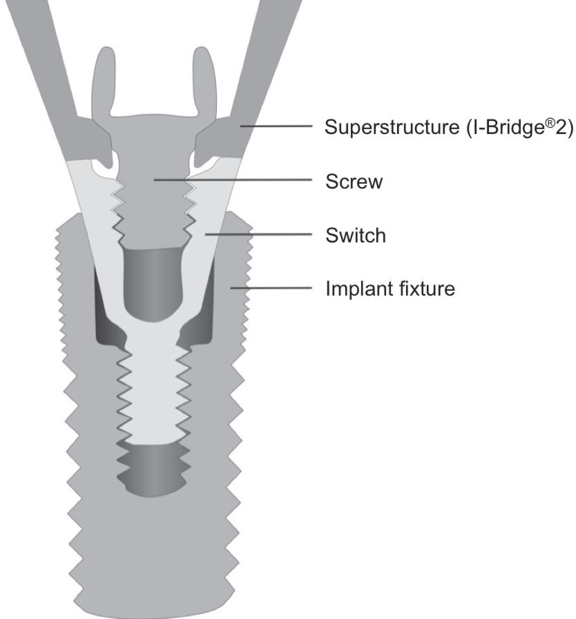
One example of a screw-retained FDP is the I-Bridge®2, introduced in 2005 by Biomain (Biomain AB, Helsingborg, Sweden). This kind of restoration is a CAD/CAM-milled implant bridge of either titanium or cobalt chromium alloy with the possibility of angling the screw channels by up to 20º. Due to this angulation, the screw channels can be placed at the oral side of the FDP, especially in the anterior region, thus making it possible to build FDPs with larger spans with satisfactory aesthetics. Furthermore, this system is compatible with most established implant systems, since the FDP can be directly connected to the fixture or with a special abutment between the implant and framework, e.g. with Astra Tech (see Figure 1).
There is a lack of information about the mechanical characteristics of screw-retained FDPs, especially when these are connected directly with the implant fixture. The authors expect major stresses and distortions within the connection area and the screw which may affect the mechanical characteristics of these restorations. The aim of the present study was therefore to evaluate the load-bearing capacity of a five-unit milled titanium implant framework (I-Bridge®2, Biomain AB, Helsingborg, Sweden) supported by three implants and to test the influence of artificial aging from cyclic mechanical loading on the load-bearing capacity. Additionally, failed specimens were micro- and macroscopically analyzed to identify the failure modes.
The hypotheses to be tested within the present study were: 1) Load-bearing capacity of screw-retained, five-unit milled titanium implant frameworks supported by considerably angulated implants is higher than static functional forces occurring in the posterior region. 2) Even after extended cyclic mechanical loading specimens show a stable implant-framework connection and a sufficient load-bearing capacity for use in the posterior area.
MATERIAL AND METHODS
Fabrication of the master model and framework pattern
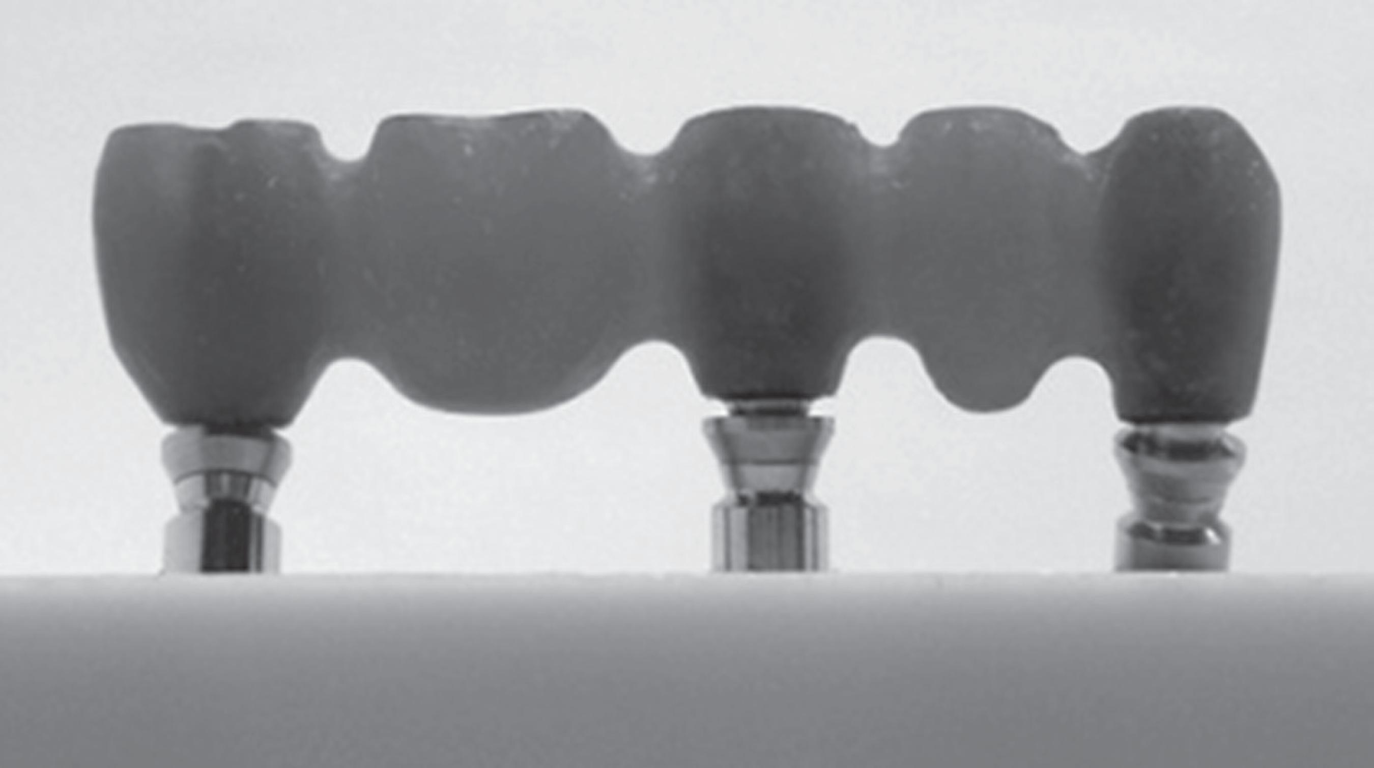
For each test specimen, three implants had to be reproducibly placed into a bone-simulating socket. A master model was prepared for this purpose: a silicone negative (Optosil®, Heraeus Kulzer, Hanau, Germany) of a block - 55 mm in length, 25 mm in height and 25 mm in depth - served as the parent for all sockets. The silicone form was cast once with polyurethane (AlphaDie Top®, Schütz Dental GmbH, Rosbach, Germany) to generate a master socket for the implants in order to simulate placement in the right mandibular canine (43), the right mandibular second premolar (45) and the right mandibular second molar (47) region. To mimic a realistic clinical worst-case scenario with respect to the shape of the mandibular jaw, the implants were angulated as follows: 43: 30º buccal angulation, 45: no angulation, 47: 30º lingual angulation. Drilling holes for implant analogues were prepared with a device for the manufacturing of surgical templates (gonyX®, Straumann GmbH, Freiburg, Germany), thus guaranteeing the predefined angulation and drilling hole depth. Implant analogues were placed into the drilling holes and fixed with acrylic resin (Palavit® G, Heraeus Kulzer, Hanau, Germany) in such a manner that a simulated bone loss of 3 mm from the implant shoulder was considered in accordance with ISO 148011515- Mutluay MM, Ruyter IE. Evaluation of bond strength of soft relining materials to denture base polymers. Dent Mater. 2007;23:1373-81.. The distances between the center points of the implants were 14 mm (43-45) and 19 mm (45-47). In the next step, the implant analogues were prepared for modelling an I-Bridge®2 master framework by adding viscous acrylic resin (Pattern Resin LS, GC International Corp., Tokyo, Japan) (see Figure 2). For this purpose, special components of the I-Bridge®2 system, called the I-FlexTM (see Figure 3), were fixed at the implant analogues. The I-FlexTM is a screw with a spherical head that serves as a substructure for the modelling and is used to define the angling of the screws connecting the implant and the framework. Modelling caps were then placed onto the substructure and the FDP was modelled in such a manner that the occlusal surfaces were planar, except for both pontics, where small cavities were included for the exact load application. The distance between the shoulder of the middle implant and the occlusal surface was 12 mm (Figure 2). Finally, the whole model was sent to the manufacturer (Biomain®), for scanning of the implant situation and the master framework and for milling 10 identical titanium frameworks according to the I-Bridge®2 system.
Special components of the I-Bridge®2 system, called the I-Flex™, placed on the implants prior to master framework modelling
Fabrication of specimens
Using the special abutment (Biomain®) as interconnecting components (see also Figure 1), original implants (OsseoSpeedTM 4.0 S, 13 mm length, Astra Tech, Mölndal, Sweden) were fixed to the frameworks with the corresponding screws. The framework-implant assemblies were then consecutively placed in the above mentioned silicone negative which was afterwards poured out with polyurethane (AlphaDie Top®, Schütz Dental GmbH, Rosbach, Germany). After the curing process was finished, all implant-framework connections were removed. To assure reproducible assemblies, the abutment and the frameworks were reconnected to the implants with the corresponding screws and the torque given by the manufacturer (implant-abutment 15 Ncm, abutment-framework 20 Ncm). Five specimens were randomly selected for cyclic mechanical loading and prepared with a resilient silicone bearing at the socket (Mollosil Plus, DETAX, Ettlingen, Germany), in order to prevent socket fracture due to non-planar contact during cyclic loading.
Cyclic mechanical loading
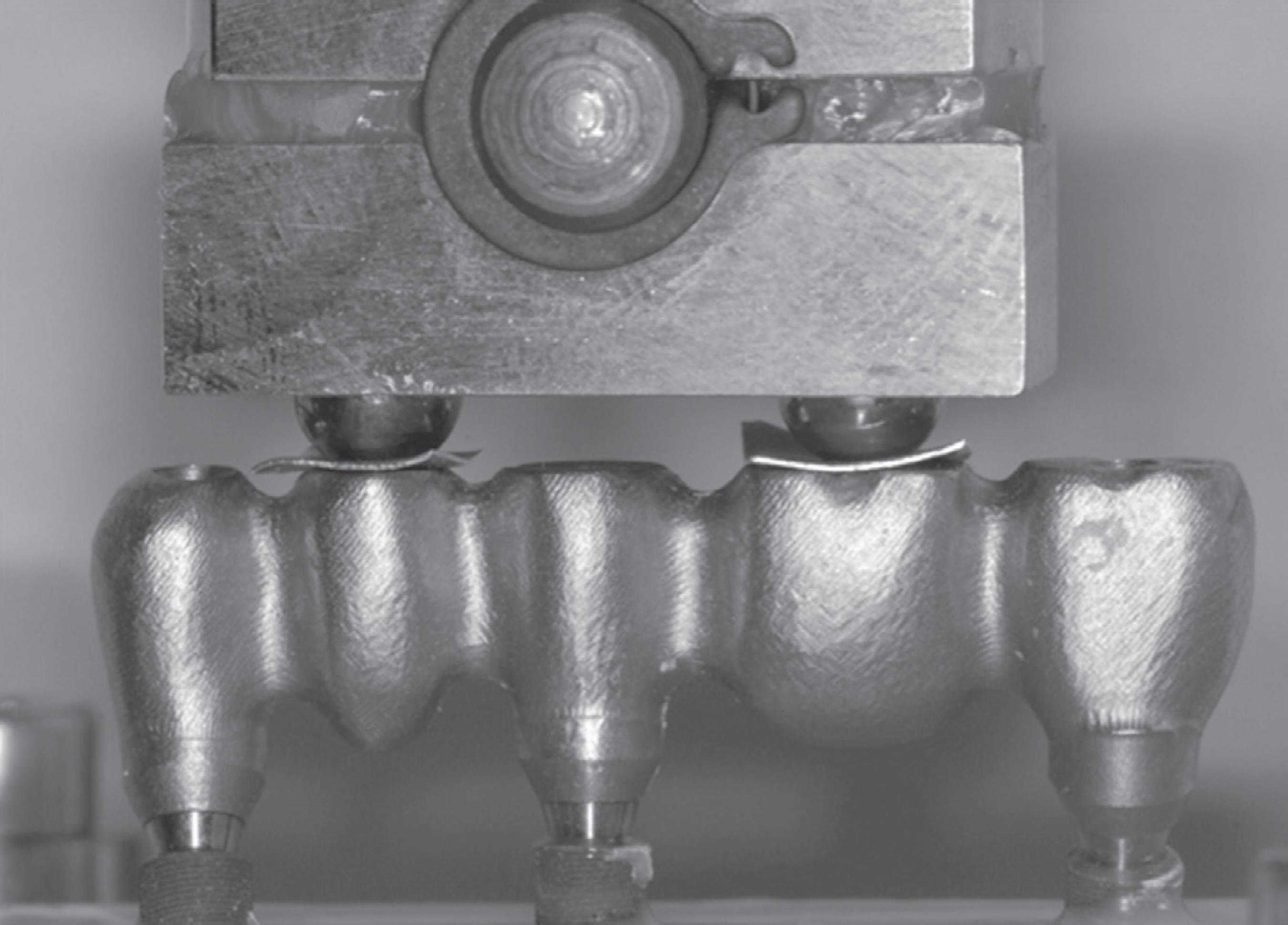
Specimens of the test group underwent five million cycles of mechanical loading in a chewing simulator (machine shop, Hannover Medical School, Hannover, Germany), with 100 N as the upper load limit at a frequency of 2.5 Hz prior to final testing. After every 250,000 load cycles, the specimens were macroscopically checked to see whether the screws had loosened or failed. For this purpose, the mechanical loading was stopped and the specimens were macroscopically evaluated by visual inspection regarding the potential changes in the construction. Furthermore, the stiffness of the screw connection was tested by use of the recommended screw driver without applying an additional force to the complex. As Figure 4 shows, the load was applied onto the pontics at two points 16.5 mm apart via two tungsten carbide balls (diameter 6.0 mm) on interposed tin foils (thickness 0.2 mm) to ensure an equally distributed load application. The loading piston was mounted using an intermediate silicone layer (Mollosil Plus, DETAX, Ettlingen, Germany) to prevent point-wise overload and to guarantee a homogeneous load application (see Figure 4). Since a survey has revealed that the average number of chewing cycles is about 800,000 per year2525- Rosentritt M, Behr M, Gebhard R, Handel G. Influence of stress simulation parameters on the fracture strength of all-ceramic fixed-partial dentures. Dent Mater. 2006;22(2):176-82., the five million cycles applied in this study corresponded to an in-vivo service period of approximately 75 months (6 years, 3 months).
I-Bridge®2 in the universal test instrument prior to cyclic mechanical loading. The force was transferred to the pontics via two tungsten carbide balls
Load until failure testing
After cyclic mechanical loading, the resilient silicone socket bearing and the tin foils were removed and the test and control specimens were loaded in a universal testing machine (Type 20K, UTS Testsysteme, Ulm-Einsingen, Germany). Load-displacement curves were recorded until failure (defined as a drop in load of more than 500 N, see Figure 5). The load piston was the same as that used for the cyclic mechanical loading; the crosshead speed was 1 mm/min. The statistical analysis was performed using the t-test for independent groups, with the level of significance set at p=0.05.
Failure analysis
Before and after testing, all specimens were macro- and microscopically analyzed at the interface of the implant and superstructure, using a reflected light microscope (M3Z, Wild, Heerbrugg, Switzerland). Failure modes were documented via a digital camera (ProgRes C12 plus, Jenoptik, Jena, Germany) with all pictures including a scale bar. Changes in the frameworks' geometry due to load testing were evaluated by comparing pictures of the specimens before and after the testing procedure.
Additionally, one specimen from each test group was selected for cross-sectional analysis. For this purpose, the specimens were embedded in clear methylmethacrylate (Acryfix, Struers GmbH, Willich, Germany) and mid-sectioned along the longitudinal axis of each implant in the bucco-lingual direction using a diamond saw (IsoMet 4000, Buehler, Illinois, USA). After polishing the cross-sectional surface to a roughness depth of less than 9 µm, the internal configuration was visually inspected and photographed under a reflected-light microscope (M3Z, Wild, Heerbrugg, Switzerland) at tenfold magnification to evaluate the failure mode.
RESULTS
All specimens survived cyclic mechanical loading and no obvious failure or screw loosening could be observed. Load-displacement curves showed a more or less steep increase until a maximum force was reached, followed by a gradually decreasing force and, finally, failure.
Table 1 and Figure 6 show the results of the load-bearing capacity testing. In comparison to the control group with a load-bearing capacity of 8,496 N±196 N, the aged specimens exhibited a broad decrease in load-bearing capacity to 7,592 N±901 N. However, the cyclic mechanical loading did not significantly influence the load-bearing capacity (p=0.060).
Mean values (MV), standard deviations (SD), medians (MD), maximum (Max) and minimum (Min) are given
Box chart representing load-bearing capacity for both test groups. Medians and quartiles are given
External inspection of the specimens revealed an identical failure mode for all specimens. Large deformations of the titanium framework in the abutment area accompanied by a loss of vertical dimension were obvious. Nevertheless, all FDPs were still fixed on the implants and no screw fracture could be detected.
Analyses of cross-sections showed framework fractures near the abutment in both the control and test group (see Figure 7A-C). Furthermore, the screw threads of the abutment and the implant were deformed. In one case, the implant head even fractured in the middle of the thread.
Polished cross-sections of embedded failed specimens of the differently angulated implants (a: +30°, b: 0°, c: -30°). Large deformations of the framework at the implant connection area are obvious
DISCUSSION
Dental implants are subjected to functional loading during their period of wear in vivo. Hence, it is of crucial importance to consider cyclic mechanical loading when evaluating the long-term behaviour of implant-supported restorations in vitro. Fatigue testing until failure is accepted as a method to generate data on the fracture strength and implant longevity2323- Quek HC, Tan KB, Nicholls JI. Load fatigue performance of four implant-abutment interface designs: effect of torque level and implant system. Int J Oral Maxillofac Implants. 2008;23(2):253- 62. , 2626- Sailer I, Sailer T, Stawarczyk B, Jung RE, Hammerle CH. In vitro study of the influence of the type of connection on the fracture load of zirconia abutments with internal and external implant-abutment connections. Int J Oral Maxillofac Implants. 2009;24(5):850-8.. A standardized guideline (ISO 14801) for the dynamic fatigue testing of single implants has been established by the International Organization for Standardization1515- Mutluay MM, Ruyter IE. Evaluation of bond strength of soft relining materials to denture base polymers. Dent Mater. 2007;23:1373-81.. In contrast to single implant testing, testing of multi-implant supported FDPs is not yet standardized, but the experimental setup of the present study was carefully chosen to be in accordance with ISO 14801. Furthermore, an unfavourable clinical situation was imitated as best as possible: the distance between the implant shoulder and crestal bone level was adjusted to 3 mm in order to represent a typical reduction in the bone support, as recommended in ISO 148011515- Mutluay MM, Ruyter IE. Evaluation of bond strength of soft relining materials to denture base polymers. Dent Mater. 2007;23:1373-81.. To mimic natural bone, the implants were embedded in reinforced polyurethane with an elastic modulus similar to that of bone2727- Scherrer SS, de Rijk WG. The fracture resistance of all-ceramic crowns on supporting structures with different elastic moduli. Int J Prosthodont. 1993;6(5):462-7.. Moreover, since in numerous clinical situations implants are angulated to the restoration's axis, in particular in the vestibulo-oral direction33- Atsü SS, Kilicarslan MA, Kucukesmen HC, Aka PS. Effect of zirconium-oxide ceramic surface treatments on the bond strength to adhesive resin. J Prosthet Dent. 2006;95:430-6., in the current test scenario the anterior (43 region) and the posterior implant (47 region) were angulated 30º off-axis in the buccal and lingual directions, respectively. Cyclic mechanical loading was performed with a chewing simulator and an upper load limit of 100 N, which is in accordance with the average bite forces of between 20 N and 120 N, depending on the nutrition's hardness2828- Schindler HJ, Stengel E, Spiess WE. Feedback control during mastication of solid food textures - a clinical-experimental study. J Prosthet Dent. 1998;80(3):330-6.. However, a fixed number of mechanical cycles (five million) was applied, representing an in vivo service period of approximately 75 months (6 years, 3 months)2525- Rosentritt M, Behr M, Gebhard R, Handel G. Influence of stress simulation parameters on the fracture strength of all-ceramic fixed-partial dentures. Dent Mater. 2006;22(2):176-82.. This period of wear makes it possible to draw conclusions on the long-term behaviour of the implant components77- Jiao C, Wang Z, Gui Z, Hu Y. Silane grafting and crosslinking of ethylene-octene copolymer. Eur Polym J. 2005;41:1204-11.. Even though tests were performed under highly realistic conditions, the significance of the present study may be limited due to the sample size of only five specimens per group. Notwithstanding this, the number of test samples seems to be adequate, since several other authors have conducted studies on implant connection stability with the same sample size99- Kawano F, Dootz ER, Koran A 3rd, Craig RG. Comparison of bond strength of six soft denture liners to denture base resin. J Prosthet Dent. 1992;68:368-71. , 1010- Khan Z, Martin J, Collard S. Adhesion characteristics of visible light-cured denture base material bonded to resilient lining materials. J Prosthet Dent. 1989;62:196-200. , 2323- Quek HC, Tan KB, Nicholls JI. Load fatigue performance of four implant-abutment interface designs: effect of torque level and implant system. Int J Oral Maxillofac Implants. 2008;23(2):253- 62..
In a systematic review, Berglundh, et al.55- Dogan OM, Keskin S, Dogan A, Ataman H, Usanmaz A. Structureproperty relation of a soft liner material used in denture applications. Dent Mater J. 2007;26:329-34. (2002) showed that technical complications related to implant components and superstructures were reported in 60-80% of the studies included, in contrast to biological complications in only 40-60% of the studies55- Dogan OM, Keskin S, Dogan A, Ataman H, Usanmaz A. Structureproperty relation of a soft liner material used in denture applications. Dent Mater J. 2007;26:329-34.. Screw loosening and joint failure are major problems66- Jacobsen NL, Mitchell DL, Johnson DL, Holt RA. Lased and sandblasted denture base surface preparations affecting resilient liner bonding. J Prosthet Dent. 1997;78:153-8. , 1919- Polyzois GL, Frangou MJ. Influence of curing method, sealer, and water storage on the hardness of a soft lining material over time. J Prosthodont. 2001;10:42-5.. In the present study, no screw loosened or failed during the cyclic mechanical loading. The locking of multiple implants seems to stabilize the whole implant-framework assembly1111- Kulak-Ozkan Y, Sertgoz A, Gedik H. Effect of thermocycling on tensile bond strength of six silicone-based, resilient denture liners. J Prosthet Dent. 2003;89:303-10.. Furthermore, this may be due to the passive fit of the CAD/CAM-milled I-Bridge®2. Abduo, et al.11- Amin WM, Fletcher AM, Ritchie GM. The nature of the interface between polymethyl methacrylate denture base materials and soft lining materials. J Dent. 1981;9:336-46. (2011) considered that the CAD/CAM is the most consistent method for screw-retained implant frameworks, potentially giving an excellent fit11- Amin WM, Fletcher AM, Ritchie GM. The nature of the interface between polymethyl methacrylate denture base materials and soft lining materials. J Dent. 1981;9:336-46.. In contrast, Eliasson, et al.1111- Kulak-Ozkan Y, Sertgoz A, Gedik H. Effect of thermocycling on tensile bond strength of six silicone-based, resilient denture liners. J Prosthet Dent. 2003;89:303-10. (2010) reported clinically acceptable I-Bridges® without passive fitting1111- Kulak-Ozkan Y, Sertgoz A, Gedik H. Effect of thermocycling on tensile bond strength of six silicone-based, resilient denture liners. J Prosthet Dent. 2003;89:303-10..
The load-bearing capacity of the I-Bridge®2 even after cyclic mechanical loading was 7,592 N, which is much higher than maximum bite forces. These range approximately between 150 N and 880 N in the posterior region, depending on experimental conditions and the individual1212- León BL, Del Bel Cury AA, Rodrigues Garcia RC Water sorption, solubility, and tensile bond strength of resilient denture lining materials polymerized by different methods after thermal cycling. J Prosthet Dent. 2005;93:282-7. , 1313- Morshedian J, Hoseinpour PM, Azizi H, Parvizzad R. Effect of polymer structure and additives on silane grafting of polyethylene. Express Polym Lett. 2009;3:105-15. , 1717- Pinto JR, Mesquita MF, Henriques GE, Arruda Nóbilo MA. Effect of thermocycling on bond strength and elasticity of 4 long-term soft denture liners. J Prosthet Dent. 2002;88:516-21.. Nevertheless, large deformations of the framework were obvious in the connection area of the implant. The onset of plastic deformation typically appears earlier than the load drop which defined failure. Hence, it is possible that some of the veneering layer may delaminate in clinical practice before failure sets in. As the load-bearing capacity of the I-Bridge®2 achieves approximately tenfold the maximum bite forces, it can be assumed that this phenomenon may be quite rare. As a limitation of the present study, it has to be mentioned that the frameworks fabricated were a little bulkier than many actual clinical frameworks, thus resulting in a higher load-bearing capacity.
The present results suggest that screw-retained implant bridges are sufficient to rehabilitate partial and total edentulous jaws. A recently published long-term evaluation of full-arch implant bridges is in accordance with these findings2424- Ravald N, Dahlgren S, Teiwik A, Gröndahl K. Long-term evaluation of Astra Tech and Brånemark implants in patients treated with full-arch bridges. Results after 12-15 years. Clin Oral Implants Res. 2012 Jul 4. [Epub ahead of print]. However, it has to be emphasized that just one specific implant system was included in this study, so that conclusions for other systems are hard to draw. Furthermore, long-term success depends on additional aspects, e. g. peri-implant soft tissue complications1414- Mulik S, Sotiriou-Leventis C, Leventis N. Adhesion enhancement of polymeric films on glass surfaces by a silane derivative of azobisisobutyroni trile (AIBN). Polymer Preprints. 2008;49:498-9..
CONCLUSION
The load-bearing capacity of the I-Bridge®2 frameworks is much higher than the clinical relevant occlusal forces, even with non-optimally placed implants, so that there is a huge safety margin. The cyclic mechanical loading did not significantly influence the load-bearing capacity, but in vivo long-term stability depends on additional aspects, e. g. bacterial microleakage.
This study was supported by Biomain, Sweden, whose support is gratefully acknowledged.
REFERENCES
-
1- Amin WM, Fletcher AM, Ritchie GM. The nature of the interface between polymethyl methacrylate denture base materials and soft lining materials. J Dent. 1981;9:336-46.
-
2- Atsü SS, Gelgör IE, Sahin V. Effects of silica coating and silane surface conditioning on the bond strength of metal and ceramic brackets to enamel. Angle Orthod. 2006;76:857-62.
-
3- Atsü SS, Kilicarslan MA, Kucukesmen HC, Aka PS. Effect of zirconium-oxide ceramic surface treatments on the bond strength to adhesive resin. J Prosthet Dent. 2006;95:430-6.
-
4- Demir H, Dogan A, Dogan OM, Keskin S, Bolayir G, Soygun K. Peel bond strength of two silicone soft liners to a heat-cured denture base resin. J Adhes Dent. 2011;13(6):579-84.
-
5- Dogan OM, Keskin S, Dogan A, Ataman H, Usanmaz A. Structureproperty relation of a soft liner material used in denture applications. Dent Mater J. 2007;26:329-34.
-
6- Jacobsen NL, Mitchell DL, Johnson DL, Holt RA. Lased and sandblasted denture base surface preparations affecting resilient liner bonding. J Prosthet Dent. 1997;78:153-8.
-
7- Jiao C, Wang Z, Gui Z, Hu Y. Silane grafting and crosslinking of ethylene-octene copolymer. Eur Polym J. 2005;41:1204-11.
-
8- Katsumata Y, Hojo S, Hamano N, Watanabe T, Yamaguchi H, Okada S, et al. Bonding strength of autopolymerizing resin to nylon denture base polymer. Dent Mater J. 2009;28:409-18.
-
9- Kawano F, Dootz ER, Koran A 3rd, Craig RG. Comparison of bond strength of six soft denture liners to denture base resin. J Prosthet Dent. 1992;68:368-71.
-
10- Khan Z, Martin J, Collard S. Adhesion characteristics of visible light-cured denture base material bonded to resilient lining materials. J Prosthet Dent. 1989;62:196-200.
-
11- Kulak-Ozkan Y, Sertgoz A, Gedik H. Effect of thermocycling on tensile bond strength of six silicone-based, resilient denture liners. J Prosthet Dent. 2003;89:303-10.
-
12- León BL, Del Bel Cury AA, Rodrigues Garcia RC Water sorption, solubility, and tensile bond strength of resilient denture lining materials polymerized by different methods after thermal cycling. J Prosthet Dent. 2005;93:282-7.
-
13- Morshedian J, Hoseinpour PM, Azizi H, Parvizzad R. Effect of polymer structure and additives on silane grafting of polyethylene. Express Polym Lett. 2009;3:105-15.
-
14- Mulik S, Sotiriou-Leventis C, Leventis N. Adhesion enhancement of polymeric films on glass surfaces by a silane derivative of azobisisobutyroni trile (AIBN). Polymer Preprints. 2008;49:498-9.
-
15- Mutluay MM, Ruyter IE. Evaluation of bond strength of soft relining materials to denture base polymers. Dent Mater. 2007;23:1373-81.
-
16- Peutzfeldt A, Asmussen E. Silicoating: evaluation of a new method of bonding composite resin to metal. Scand J Dent Res. 1988;96:171-6.
-
17- Pinto JR, Mesquita MF, Henriques GE, Arruda Nóbilo MA. Effect of thermocycling on bond strength and elasticity of 4 long-term soft denture liners. J Prosthet Dent. 2002;88:516-21.
-
18- Pinto JR, Mesquita MF, Nóbilo MA, Henriques GE. Evaluation of varying amounts of thermal cycling on bond strength and permanent deformation of two resilient denture liners. J Prosthet Dent. 2004;92:288-93.
-
19- Polyzois GL, Frangou MJ. Influence of curing method, sealer, and water storage on the hardness of a soft lining material over time. J Prosthodont. 2001;10:42-5.
-
20- Shimizu H, Kawaguchi T, Yoshida K, Tsue F, Takahashi Y. Effect of surface preparation on the failure load of a highly filled composite resin bonded to a denture base resin. J Prosthodont. 2009;18:684-7.
-
21- Wong WK, Varrall DC. Role of molecular structure on the silane cross-linking of polyethylene: the importance of resin molecular structure change during silane grafting. Polymer. 1994;35:5447-52.
-
22- Yilmaz K, Ozkan P. Profilometer evaluation of the effect of various polishing methods on the surface roughness in dental ceramics of different structures subjected to repeated firings. Quintessence Int. 2010;41:125-31.
-
23- Quek HC, Tan KB, Nicholls JI. Load fatigue performance of four implant-abutment interface designs: effect of torque level and implant system. Int J Oral Maxillofac Implants. 2008;23(2):253- 62.
-
24- Ravald N, Dahlgren S, Teiwik A, Gröndahl K. Long-term evaluation of Astra Tech and Brånemark implants in patients treated with full-arch bridges. Results after 12-15 years. Clin Oral Implants Res. 2012 Jul 4. [Epub ahead of print]
-
25- Rosentritt M, Behr M, Gebhard R, Handel G. Influence of stress simulation parameters on the fracture strength of all-ceramic fixed-partial dentures. Dent Mater. 2006;22(2):176-82.
-
26- Sailer I, Sailer T, Stawarczyk B, Jung RE, Hammerle CH. In vitro study of the influence of the type of connection on the fracture load of zirconia abutments with internal and external implant-abutment connections. Int J Oral Maxillofac Implants. 2009;24(5):850-8.
-
27- Scherrer SS, de Rijk WG. The fracture resistance of all-ceramic crowns on supporting structures with different elastic moduli. Int J Prosthodont. 1993;6(5):462-7.
-
28- Schindler HJ, Stengel E, Spiess WE. Feedback control during mastication of solid food textures - a clinical-experimental study. J Prosthet Dent. 1998;80(3):330-6.
-
29- Sherif S, Susarla SM, Hwang JW, Weber HP, Wright RF. Clinician- and patient-reported long-term evaluation of screw- and cement-retained implant restorations: a 5-year prospective study. Clin Oral Investig. 2011;15(6):993-9.
-
30- Weber HP, Sukotjo C. Does the type of implant prosthesis affect outcomes in the partially edentulous patient? Int J Oral Maxillofac Implants. 2007;22(Suppl):140-72.
Publication Dates
-
Publication in this collection
Jul-Aug 2013
History
-
Received
16 Jan 2013 -
Reviewed
26 Mar 2013 -
Accepted
10 May 2013