
ABSTRACT
We describe the circuit design, construction, and operation of a field-portable electric fish finder (an AC-coupled wide-band differential bio-amplifier with loudspeaker output). This device permits detection and monitoring of the electric organ discharges generated by neotropical gymnotiform fishes (as well as the mormyroid fishes of tropical Africa). Our design is modified from earlier versions to optimize detection performance and stability over a wider range of ambient water conductivity, including under conditions of extremely low conductivity (< ca. 10 μScm-1). Our new electric fish finder design also incorporates complete waterproofing and longer battery autonomy. We provide Gerber and Eagle files made with the electronic design automation software ‘Autodesk Eagle’ to allow researchers to order printed circuit boards directly from commercial manufacturers.
Keywords:
Bio-amplifier; Electric organ discharge; Electroreception; Gymnotiformes; Mormyridae
RESUMO
Nós descrevemos o projeto de circuitos eletrônicos e as instrucões para a construção e uso de um detector de peixes elétricos portátil (bio-amplificador diferencial de banda-larga com acoplamento AC). Este aparelho permite a detecção e o monitoramento das descargas de órgãos elétricos gerados por peixes neotropicais da ordem Gymnotiformes (assim como dos peixes mormirídeos da África Tropical). Nosso projeto é modificado a partir de versões anteriores para otimizar o desempenho e a estabilidade sob uma faixa de condutividades ambientais mais ampla, incluindo condições de condutividade extremamente baixa (< ca. 10 μScm-1). Nosso detector de peixes elétricos novo também foi otimizado a fim de proporcionar impermeabilização completa e vida longa para as baterias. Nós fornecemos arquivos ‘Gerber’ e ‘Eagle’ preparados com o software de automação de projeto eletrônico ‘Autodesk Eagle’ para permitir aos pesquisadores a possibilidade de efetuar encomendas de nossa placa de circuito impresso direitamente das empresas de fabricação.
Palavras-chave:
Bio-amplificador; Descarga de órgão elétrico; Eletrorecepção; Gymnotiformes; Mormyridae
Introduction
The Neotropical gymnotiform and tropical African mormyroid fishes are unique among teleosts in possessing a specialized electrogenic and electrosensory system, which serves for both the detection of objects in the dark (electrolocation) and for social communication and recognition (electrocommunication) (Bullock et al., 2005Bullock TH, Hopkins CD, Popper AN, Fay RR, editors. Electroreception. New York: Springer; 2005.). All gymnotiforms and all Mormyroidea generate electric organ discharges (EODs) that can be readily detected with submerged electrodes connected to a wide-band differential bio-amplifier. Such a device, which has been variably termed an ‘electric fish finder’ (henceforth ‘EFF’), or ‘electric fish detector’, greatly increases the rate at which electric fish can be sampled in their natural habitats.
A properly designed EFF permits the rapid location of electric fish of all sizes (including larval and post-larval individuals) from waters of variable electrical conductivity. Weakly electric gymnotiforms and mormyroids range in peak-to-peak voltage from only a few millivolts as larval individuals to up to ca. 1-2V in large Gymnotus (Crampton, 2019Crampton WGR. Electroreception, electrogenesis and signal evolution in freshwater fish. J Fish Biol . 2019; 95(1):92-134. https://doi.org/10.1111/jfb.13922
https://doi.org/10.1111/jfb.13922...
). However, the voltage detected by the EFF depends also on the conductivity of the water and the posture of the fish relative to the electrode pair. The voltage at a given distance from a dipole source declines with increasing conductivity (i.e., decreasing resistance) (Knudsen, 1975Knudsen EI. Spatial aspects of the electric fields generated by weakly electric fish. J Comp Physiol A Neuroethol Sens Neural Behav Physiol. 1975; 99(2):103-18. https://doi.org/10.1007/BF00618178
https://doi.org/10.1007/BF00618178...
), such that the range at which a given electric fish can be detected is greater in low conductivity water than in high conductivity water. Tropical freshwaters often exhibit exceptionally low electrical conductivity, including most upland Shield drainages, as well as river systems draining lowland tropical forests and savannas (ca. 3-30 μScm-1) (Roberts, 1972Roberts TR. Ecology of fishes in the Amazon and Congo basins. Bull Mus Comp Zool. 1972; 143(2):117-47.; Albert, Crampton, 2010Albert JS, Crampton WGR. The geography and ecology of diversification in Neotropical freshwaters. Nature Education Knowledge. 2010; 1:13-19.; Crampton, 2019Crampton WGR. Electroreception, electrogenesis and signal evolution in freshwater fish. J Fish Biol . 2019; 95(1):92-134. https://doi.org/10.1111/jfb.13922
https://doi.org/10.1111/jfb.13922...
). Some of these tropical waters are among the most electrolyte-free natural systems on earth, and yet they host abundant communities of electric fish (Crampton, 1996Crampton WGR. Gymnotiform fish: An important component of Amazonian floodplain fish communities. J Fish Biol. 1996; 48(2):298-301. https://doi.org/10.1111/j.1095-8649.1996.tb01122.x
https://doi.org/10.1111/j.1095-8649.1996...
, 2019Crampton WGR. Electroreception, electrogenesis and signal evolution in freshwater fish. J Fish Biol . 2019; 95(1):92-134. https://doi.org/10.1111/jfb.13922
https://doi.org/10.1111/jfb.13922...
). Some tropical river systems nonetheless reach much higher conductivity, including Neotropical whitewater rivers of Andean origin and their associated floodplain systems (ca. 90-200 μScm-1), as well as rivers draining karst limestone formations (Crampton, 2011Crampton WGR. An ecological perspective on diversity and distributions. In: Albert JS, Reis RE, editors. Historical biogeography of neotropical freshwater fishes. Berkeley (CA): University of California Press; 2011. p.165-89., 2019Crampton WGR. Electroreception, electrogenesis and signal evolution in freshwater fish. J Fish Biol . 2019; 95(1):92-134. https://doi.org/10.1111/jfb.13922
https://doi.org/10.1111/jfb.13922...
).
In addition to providing adequate (but not excessive) gain over a wide range of water conductivity, an EFF must also be robust enough to tolerate rough treatment, provide several hours of battery autonomy, and be sufficiently waterproofed to protect the electronic components during heavy rainstorms and occasional accidental submergences.
Here we describe a substantially modified version of an EFF design published previously by Crampton et al. (2007Crampton WGR, Wells JK, Smyth C, Walz SA. Design and construction of an electric fish finder. Neotrop Ichthyol. 2007; 5(3):425-28. http://dx.doi.org/10.1590/S1679-62252007000300022
http://dx.doi.org/10.1590/S1679-62252007...
). Our new design is optimized for use across a wider range of electrical conductivity - including under conditions of extremely low conductivity (< ca. 10 μScm-1), making it suitable for use in all water bodies of the Neotropics and tropical Africa. Our revised design also provides enhanced durability, waterproofing, and battery autonomy.
Material and Methods
We used the electronic design automation software Eagle version 8.22 (Autodesk, San Rafael, CA) to prepare the circuit diagrams and printed circuit board (PCB) designs presented herein. We also ensured that our circuit design met our requirements using the SPICE (Simulation Program with Integrated Circuit Emphasis) simulation software LTspice version 17 (Linear Technology, Norwood, MA). We used the commercial PCB fabrication company PCBWay.com (Shenzhen, China) to manufacture our prototype PCBs. All electronic components assembled were then onto the PCBs in the Crampton Lab using basic soldering tools. The metal enclosure was drilled using a drill press and standard metal drill bits, and all parts assembled in the enclosure using basic metal workshop/electronics tools. Our new EFF circuit and enclosure designs were tested in low-conductivity streams (3-30 μScm-1) and high-conductivity whitewater floodplain floating meadow systems (60-200 μScm-1) of the lower Amazon basin of Brazil.
Results
GitHub repository. At a permanent GitHub repository (link below) we provide a full suite of Autodesk ‘Gerber’ and ‘Eagle’ files for our new circuit schematic (Fig. 1) and PCB layout (Fig. 2). https://github.com/Crampton-Lab/Electric-Fish-Finder-V1.0/
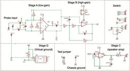
Electric fish finder circuit schematic in Autodesk Eagle format. BATT = battery, C = capacitor, CHGRND = chassis ground, GND = ground, JP = connector socket, R = resistor, SPK = speaker, VCC = voltage common collector. Integrated circuits are: INA = instrumentation amplifier INA128PA; NEB = operational amplifier NE5532; LM386 = audio amplifier LM386N-1; TLE = virtual ground TLE2425IP. This schematic matches the printed circuit board layout in Fig. 2.
These Gerber and Eagle files are required by commercial PCB manufacturing companies, which will fabricate and send small numbers of PCBs rapidly and at low cost. The electronic components listed in Tab. 1 can then be soldered to the PCBs with basic tools. Our Gerber and Eagle files can also be edited in Autodesk Eagle, should the user wish to alter our circuit design. At the same GitHub repository, we also include a copy of the component lists provided in Tab. 1, with unit prices in US dollars. This will be updated regularly to replace components that become obsolete, and to include price changes.
At the time of online ordering, a PCB fabrication company will require the upload of a single .zip compressed file containing the eight Gerber files for the desired PCB. For instance, the .zip file eFish_Finder_V1.0_Gerber-files.zip at our GitHub site should be provided to order version A of our EFF circuit (see below for notes on Version A and B). The company’s website will also request the board dimensions (enter 64 x 47 mm) and the number of boards desired. All default options should otherwise be selected.
Circuit design. Our EFF is an AC-coupled differential bio-amplifier designed to amplify electric fish EODs from a submerged electrode pair. The circuit amplifies electric fish signals and passes them to a loudspeaker where they are transduced into sound. The primary function of our EFF is to determine the exact position of electric fish in their natural habitats such that they can then be captured with a dipnet or small seine net (without the need to see them). Our EFF is effective at amplifying and converting to sound signals with spectral energy in the range 70 Hz to 12.6 kHz (see Discussion for further details). To accommodate differences in body size and signal strength between different individuals and species of electric fish, and to facilitate use under a wide range of ambient conductivity, our device can be switched between low-gain (x 82 where the R1 resistor is 620Ω), high-gain (x 410 [calculated as low-gain x 5]), and off, via a three-position (3-pole double-throw) toggle switch. The main (low-gain) stage of our circuit (stage A in Fig. 1) amplifies the signal directly from the electrode pair via a Texas Instruments INA128PA low-noise differential instrumentation amplifier integrated circuit (IC). The high-gain stage of our EFF (Stage B in Fig. 1), when selected, boosts the low-gain stage by approximately x 5 with a Texas Instruments NE5532P inverting operational amplifier (op-amp) IC. The NE5532 is a low-noise high-speed op-amp designed primarily for audio applications. The final amplification stage of our EFF circuit (Stage C in Fig. 1) drives the loudspeaker output by boosting x 20 the output from stage A (at low-gain) or stages A x B (at high-gain) with a Texas Instruments LM386N-1 low-noise audio amplifier IC.
Circuit design improvements. The circuit design presented here (Figs. 1-2) is substantially modified from an earlier version (Crampton et al., 2007Crampton WGR, Wells JK, Smyth C, Walz SA. Design and construction of an electric fish finder. Neotrop Ichthyol. 2007; 5(3):425-28. http://dx.doi.org/10.1590/S1679-62252007000300022
http://dx.doi.org/10.1590/S1679-62252007...
), and contains several additional or substituted components. Below we summarize the main changes.

Virtual ground. Our new circuit design includes an active virtual ground. Because power is supplied from a DC battery pack, we now utilize a Texas Instruments TLE2426 virtual ground IC as a precision voltage reference (see Stage D in Fig. 1). This active virtual ground provides a voltage output of exactly half that provided between the input and the common terminal, thereby minimizing voltage imbalance between the V+ and V- rails (provided that the ability of the TLE2426 IC to sink and source current is not exceeded). The active virtual ground allows us to use a single 9V battery pack (instead of two separate 9V batteries in the design of Crampton et al., 2007Crampton WGR, Wells JK, Smyth C, Walz SA. Design and construction of an electric fish finder. Neotrop Ichthyol. 2007; 5(3):425-28. http://dx.doi.org/10.1590/S1679-62252007000300022
http://dx.doi.org/10.1590/S1679-62252007...
), and reduces the tendency for the INA128PA instrumentation amplifier, NE5532 op-amp, or LM386N-1 audio ICs (or a combination of these three ICs) to distort or oscillate (causing noise), especially when battery power declines. Imbalanced voltages also reduce runtime before the batteries are low. Consequently, the addition of this active virtual ground provided a substantial increase in battery life relative to the passive virtual ground of the Crampton et al. (2007Crampton WGR, Wells JK, Smyth C, Walz SA. Design and construction of an electric fish finder. Neotrop Ichthyol. 2007; 5(3):425-28. http://dx.doi.org/10.1590/S1679-62252007000300022
http://dx.doi.org/10.1590/S1679-62252007...
) design.
Instrumentation amplifier gain resistance. We increased the resistance gain (Rg) to the main gain stage of new EFF circuit (stage A, Fig. 1), which is determined by the resistance of R1 positioned between pin 1 and 8 of INA128PA. Our new circuit design specifies an R1 resistance of 620Ω, versus 400Ω in our earlier design. This modification limits overloading of strong input signals at very low conductivities (< 10 μScm-1) and helps to suppress internal oscillations of INA128PA that can lead to high-frequency screeching. The gain of INA128PA is calculated by the formula 1 + (50kΩ / Rg) (+/- 1% for manufacturer tolerance of R1) for a differential amplifier (Ulaby, Maharbiz, 2010Ulaby FT, Maharbiz MM. Circuits. Austin (TX): National Technology and Science Press; 2010.); here the 50 kΩ constant is from the IC specifications. To further suppress noise, we also included a simple termination of the INA128PA input terminals with a 2.2 nF capacitor (C4 in Figs. 1-2). Following Ulaby and Maharbiz (2010Ulaby FT, Maharbiz MM. Circuits. Austin (TX): National Technology and Science Press; 2010.), we calculated the gain of the NE5332 as 4.8 x, by dividing the R6 resistance (270kΩ) by the R4 resistance (56kΩ). The presence of capacitor C6 at NE5332 (which acts as a filter) reduces gain for higher signal frequencies, but LTspice simulation confirmed that over the range of most electric fish EOD peak-power-frequencies, the gain approximates x 5. Therefore, the gain of our device at high gain approximates x 82 (low gain from INA128PA where Rg = 620Ω) multiplied by x 5 (NE5332) = x 410.
At the GitHub repository we provide two alternative schematics for our circuit. Version A has solder pads for the permanent installation of a 620Ω (or other) resistor at R1. Version B instead features a 2-position connector socket at the same location (JP6 in Figs. 1-2) at which an R1 resistor can be added manually and switched out at any time. For instance, if the user intends to use the device to detect large weakly electric fish at low conductivity water, a higher-resistance R1 can used to reduce the gain (e.g., 2kΩ yields a stage A gain of x 26 following the formula described above). An even higher resistance may be used if the EFF will be used primarily to locate strongly electric eels (Electrophorus spp.) (e.g., 25kΩ yields a stage A gain of x2) (see Discussion). Conversely, if the user intends to locate weakly electric fish in high-conductivity systems, especially small individuals, a lower-resistance R1 can be installed to increase gain (e.g., 180Ω yields a stage A gain of x 278). A 620Ω resistor at R1 will nonetheless provide good performance for locating weakly electric fish across a wide range of conductivities and fish sizes. We recommend using resistors with 0.6 wattage rating and 1% tolerance throughout our circuit.
Power supply buffering. We added an electrolytic 470 μF decoupling capacitor between the 9V DC power supply and ground (GND) (C8 in Fig. 1). This provides buffering in the case of random spikes of DC voltage from the battery, which would otherwise be picked up, amplified, and outputted through the loudspeaker as noise.
Grounding of the LM-386 audio amplifier IC. In both versions A and B of our circuit plan we provide a 2-position connector socket (see JP1 in Figs. 1-2), which is currently unused. By adding a connector header to short the two poles of this connector socket (or by bridging with wire), pin 7 of the LM386N-1 IC can be connected to ground (at both the high-gain and low-gain positions). We provide this option in case of noise problems in water of exceptionally low conductivity. Nonetheless, with this connector socket left unused, we observed satisfactory performance in water as low as 3 μScm-1, which is at the extreme low end of naturally occurring conductivity ranges.
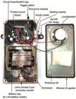
Grounding the PCB to the chassis: We added a solder pad to ground the PCB to the chassis (see CHGND in Figs. 1-2). A short length of 22-awg wire connects this solder pad to the internal surface of the aluminum enclosure (Figs. 3, 5). This design modification assists with noise suppression.
Battery pack and loudspeaker disconnection. Our revised EFF design provides two-pin connectors for rapid disconnection of the battery pack and loudspeaker (see BATT and SPK in Figs. 1-2, respectively). 9V DC power is provided by six 1.5V AA batteries (alkaline or rechargeable lithium). Our new circuit design provides ca. 24 h of continuous operation at high gain and 36 h at low gain (tested with Panasonic Eneloop rechargeable batteries).
Enclosure and waterproofing. The enclosure of our EFF (Figs. 3-5) utilizes the same Hammond aluminum box (153 x 82 x 50 mm maximum external dimensions) utilized in the version described by Crampton et al. (2007Crampton WGR, Wells JK, Smyth C, Walz SA. Design and construction of an electric fish finder. Neotrop Ichthyol. 2007; 5(3):425-28. http://dx.doi.org/10.1590/S1679-62252007000300022
http://dx.doi.org/10.1590/S1679-62252007...
). This enclosure is durable, can be easily drilled, an is waterproofed to IP67 standard by a silicone lid gasket (Fig. 3), and by rubber O-rings for all six lid screws. In our revised EFF design we incorporated a panel-mounted female socket and accompanying cable-mounted male connector from the Lemo waterproof connector family (Tab. 1, Figs. 3-4). These are complete watertight when mated. The Lemo female connector hole can optionally be keyed to prevent rotation in the enclosure. This can be accomplished by drilling an 18 mm hole (rather than the 20 mm hole show in Fig. 5) and then using a Dremel tool with metal grinding bit to bore the hole out to 20 mm while leaving a horizontal key lip at the top (following the manufacturer hole/key template for the EGG.2K.303.CLL panel mount).
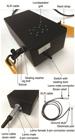
External view of electric fish finder (above, bottom left) and electrode cable/connector assembly (bottom right).

Design schematic for electric fish finder enclosure. Grey arrows show distances from edges to the center of drill holes/objects. Grey dotted circles represent drill holes. The sealing washer marked with an asterisk has no waterproofing function and is used instead to trap the exposed terminal of a wire from the channel ground against the internal metal surface of the enclosure (see CHGND in Fig. 2).
We sealed all other potential water ingress-points by using: (1) galvanized steel/bonded rubber sealing washers at the holes drilled to secure the jig bolt and swivels (to which we attached a carrying strap) (Figs. 3-5); (2) a toggle switch with a rubber O-ring that presses against the inside wall of the enclosure, and an external rubberized sealing boot that prevents ingress of water around the switch pillar (Tab. 1, Figs. 3-5); (3) a loudspeaker with a polymer cone, which we affixed to the interior enclosure lid surface by electronics grade silicone (this prevents entry of water via the holes drilled in the lid for the loudspeaker output) (Tab. 1, Figs. 3-5).
We tested the waterproofing of our EFF by immersion to 1m depth for 20 minutes. Nonetheless, we recommend that the unit is not routinely submerged. It is also essential to ensure that all seals and O-rings are in good condition and replaced every 2-5 years, depending on use. Should any water enter the enclosure, the device should be switched off immediately and the battery pack disconnected. The enclosure should then be opened and dried in strong sunlight and placed afterwards in an airtight box with silica gel desiccant for several hours. We recommend carrying a spare set of screws and rubber O-rings for the enclosure lid, and a spare switch sealing boot.
The schematic in Fig. 5 illustrates the hole pattern for the loudspeaker output, and the positions and sizes of the drilled holes that accommodate the switch, Lemo 3-pin cable connector, and jig bolts. We used two steel L-brackets to partition the enclosure into a PCB/switch bay, a battery bay, and a probe bay (Figs. 3, 5). These brackets were glued into place with silicone sealant. To secure the battery pack we also used silicone sealant to affix strips of packing foam onto the sides of the battery bay, and to the lid above the battery bay. We also used silicone sealant to attach a small rectangle of thin acrylic sheeting to the base of the PCB bay (see Fig. 3). This prevents the solder contacts on the underside of the assembled PCB from touching the metal enclosure surface. The PCB board itself is held in place by the wires connecting it to the switch and probe input, and therefore does not need to be tethered to the enclosure.
Electrode assembly. The electrode assembly for our EFF comprises a ca. 1.8 m length of XLR microphone cable (2-pin cable with metal ground shield) attached to a male 3-pin Lemo probe connector and strain relief (Tab. 1, Fig. 4). The cable probe is intended to be field-mounted with cable ties or duct tape to a simple wooden stick or cane of approximately 1.3 m length and 20 mm width. This arrangement is optimal for detecting electric fish in shallow streams and swamps, or (from a canoe) in the floating meadows of floodplain systems. The two channels of the cable should be separated by about 10 cm, and their copper wire exposed with a wire-stripper at the terminal 2-3 mm (with approximately equal exposure on each wire). The grounded shield should be cut back to a short stub. We recommend wrapping the ground shield with tape or heat shrink to prevent it from touching the wet stick (this can cause screeching when the electrodes are removed from the water). For most applications the two exposed wires should jut out about 2-4 cm from the stick, one near the end, and the other about 10 cm further up the stick. If one wire is in the water, and the other above the water surface, screeching can occur in the high-gain position. Therefore, for EFF operation in shallow water we recommend making a T- or shallow Y-shaped stick to ensure that both wires and the ground are all simultaneously submerged. Our EFF can be adapted for detecting electric fish in deep water by utilizing a long, shielded microphone cable attached to a weighted cable. Electric fish can be detected to 20 m or more depth using a 50 m cable. However, the signals become weaker and noisier with increasing cable length.
Carrying and transport. Our EFF is designed to be hung from a neck strap attached to the device by swivels (Fig. 4). Limiting the neck strap length so that the device hangs high on the user’s chest reduces accidental immersion of the unit when wading in deeper water. Care should be taken to avoid sharp impacts to the toggle switch during use and transportation. We recommend carrying the EFF in a small plastic case, such as the Pelican model 1120 (Pelican Products, Inc., Torrance CA), which is rugged, waterproof, and has a customizable foam insert.
Discussion
Optimal EFF design. The underwater dipole-like electrostatic fields of electric fish are attenuated at the cube root of distance from the source (Knudsen, 1975Knudsen EI. Spatial aspects of the electric fields generated by weakly electric fish. J Comp Physiol A Neuroethol Sens Neural Behav Physiol. 1975; 99(2):103-18. https://doi.org/10.1007/BF00618178
https://doi.org/10.1007/BF00618178...
). Voltage therefore declines very rapidly with distance from a fish. As the electrode pair is brought towards a fish, the loudspeaker volume of an EFF should ideally increase to a maximum (but without overloading) when the electrodes are positioned immediately in front of and behind the approximate center of the fish’s dipole-like field, with the fish positioned parallel to the axis of the electrode pair (the center of the dipole field is often approximately centered on the tail-portion of the fish, but moves in position during the EOD cycle, see Stoddard et al., 1999Stoddard PK, Rasnow B, Assad C. Electric organ discharges of the gymnotiform fishes: III. Brachyhypopomus. J Comp Physiol A Neuroethol Sens Neural Behav Physiol. 1999; 184(6):609-30. https://doi.org/10.1007/s003590050359
https://doi.org/10.1007/s003590050359...
). In other words, the loudspeaker volume of the EFF should reach maximum when the electrode pair are very close to and parallel to the fish. With the EFF configured in this way, a fish’s exact position can be rapidly determined via sweeping motions of the electrode pair. However, if a fish’s EOD overloads the amplifier when the electrodes are positioned further away (especially if more than 2-3 body lengths away from the fish), it becomes much harder to pinpoint the exact location of the fish. This is because once the point of overload has been reached, the speaker volume will no longer increase as the electrodes are brought closer to the fish. Our new EFF circuit design is optimized to not distort at low gain, even for relatively large weakly electric fish (to ca. 2V peak-to-peak voltage) positioned next to the electrodes in very low-conductivity water (< ca. 10 μScm-1). The high-gain, which amplifies the signal at the electrodes 410 times, is intended to provide first detection of a fish at a much greater range than the low-gain position (typically most large electric weakly electric fish can be detected at a range of 1-4 m in low-conductivity streams) but will overload as the electrode pair is brought closer. At the point of overload, which is detectable by a noticeable distortion of the loudspeaker output, the EFF must then be switched to low-gain.
EFFs and electric eels. Our EFF also allows detection of electric gymnotiform eels (Electrophorus spp.). Electric eels generate higher voltage EODs in the form of relatively weak electrolocation pulses generated from the Sach’s organ and posterior one-third of the Hunter’s organ (ca. 10V) and very strong predatory/defensive EODs (to 860V) generated from the main organ and anterior two-thirds of the Hunter’s organ (Crampton, 2019Crampton WGR. Electroreception, electrogenesis and signal evolution in freshwater fish. J Fish Biol . 2019; 95(1):92-134. https://doi.org/10.1111/jfb.13922
https://doi.org/10.1111/jfb.13922...
; de Santana et al., 2019de Santana CD, Crampton WGR, Dillman CB, Frederico RG, Sabaj MH, Covain R, Ready J, Zuanon J, de Oliveira RR, Mendes-Júnior RN, Bastos DA, Teixeira TF, Mol J, Ohara W, Castro e Castro N, Peixoto LA, Nagamachi C, Sousa L, Montag LFA, Ribeiro F, Waddell JC, Piorsky NM, Vari RP, Wosiacki WB. Unexpected species diversity in electric eels with a description of the strongest living bioelectricity generator. Nat Commun. 2019; 10:4000. https://doi.org/10.1038/s41467-019-11690-z
https://doi.org/10.1038/s41467-019-11690...
). In streams of ca. 10 μScm-1, the low-voltage Sach’s organ EODs of an electric eel of ca. 1 m length can be detected at 6 m distance or more with our EFF (depending upon its posture relative to the electrodes). At distances of < ca. 2-4 m these EODs will overload the amplifier, making it hard to make an accurate determination of the eels’ exact position. As described above (see Instrumentation amplifier gain resistance in Results), if the primary use of the EFF is to locate electric eels we recommend increasing the Rg for the INA128PA IC by insertion of a higher resistor value (e.g., 25 kΩ) at the R1 connector socket (JP1) of our Version B PCB.
Electric eels will sometimes approach and inspect the electrodes of our EFF and emit a volley of high-voltage EODs. These shocks overload the EFF circuit and for a few moments the device becomes insensitive while the capacitors slowly dissipate the accumulated charge. However, electric eel shocks cause no permanent damage to our circuit, despite exceeding the specified tolerance ranges for many of its components. The reason for this is twofold. First, each high-voltage pulse is very short (ca. 1-2 ms), allowing power to dissipate rapidly before damage occurs. For instance, although we utilize resistors rated to only 0.25 W, these will not heat up to beyond their tolerance during a brief high-voltage EOD, even though this may reach 860 volts in field strength, or more, at a current of around 1-2 amperes (Crampton, 2019Crampton WGR. Electroreception, electrogenesis and signal evolution in freshwater fish. J Fish Biol . 2019; 95(1):92-134. https://doi.org/10.1111/jfb.13922
https://doi.org/10.1111/jfb.13922...
). Second, over the short duration of an electric eel EOD, the signal at the electrode pair acts as a common mode voltage - i.e., where there is a similar voltage at each electrode, but where the circuitry amplifies only the differential between the electrodes. During a high-voltage EOD the amplifier goes briefly into distortion, but then slowly drains out of distortion as the capacitors release their charge and the common mode dissipates.
Frequency sensitivity. Our EFF yields a clear loudspeaker output for frequencies in the range ca. 70 Hz to 12.6 kHz. The loudspeaker we utilize is unable to reproduce frequencies at all below 35 Hz, reproduces frequencies only partially in the 35-90 Hz range (at the lower frequencies in this range only very strong signals are audible), and thereafter exhibits good frequency reproduction from 90 Hz to 21 kHz; its upper limit is designed to approximate the limit of human hearing. The INA 228PA IC has no filters and therefore amplifies from 0 Hz to well over 21 kHz. The NE5532P IC also amplifies frequencies down to 0 Hz but is configured in our circuit to have an upper cut-off frequency of ca. 12.6 kHz, following the formula (1/(2·pi·R·C)), where R = R5 resistance and C = C7 capacitance in our circuit schematic. All known pulse-type gymnotiform species have substantial signal energy in their EOD pulses within the ranges of detection of our EFF (35 Hz - 12.6 kHz), making our device suitable for detecting all pulse-type gymnotiforms. Many pulse-type gymnotiforms generate EODs at rates of less than 35 Hz but these are readily detectable to our EFF (even though the lower frequency limit for our loudspeaker is 35 Hz). This is because each pulse contains frequencies well above 35 Hz (see Crampton, 2019Crampton WGR. Electroreception, electrogenesis and signal evolution in freshwater fish. J Fish Biol . 2019; 95(1):92-134. https://doi.org/10.1111/jfb.13922
https://doi.org/10.1111/jfb.13922...
for details).
Our device should also be suitable for detecting all mormyrid species. Even those with peak power frequencies (PPFs) exceeding 13 kHz (some species reach 18 kHz, Crampton, 2019Crampton WGR. Electroreception, electrogenesis and signal evolution in freshwater fish. J Fish Biol . 2019; 95(1):92-134. https://doi.org/10.1111/jfb.13922
https://doi.org/10.1111/jfb.13922...
) likely still contain substantial EOD energy below 13 kHz and should therefore be detectable. Our device could nonetheless be optimized for mormyrids by using a 30pF capacitor at C7 (instead of 47 pF). This would increase the upper-cutoff of the NE5532P IC to 19.6 kHz.
For the sinusoidal EODs of wave-type electric fish, the fundamental frequency of the EOD, which is equivalent to the repetition rate of the EOD, is usually the same frequency as the PPF (rarely, in some species of apteronotids, the PPF corresponds to a higher harmonic of the fundamental); see Crampton (2019Crampton WGR. Electroreception, electrogenesis and signal evolution in freshwater fish. J Fish Biol . 2019; 95(1):92-134. https://doi.org/10.1111/jfb.13922
https://doi.org/10.1111/jfb.13922...
) for further details. One deep river gymnotiform species, Sternopygus branco Crampton, Hulen & Albert, 2004, has an EOD fundamental frequency and PPF of 24-35 Hz (Crampton et al., 2004Crampton WGR, Hulen KG, Albert JS. Sternopygus branco: A new species of Neotropical electric fish (Gymnotiformes: Sternopygidae) from the lowland Amazon basin, with descriptions of osteology, ecology, and electric organ discharges. Copeia. 2004; 2004(2):246-59. https://doi.org/10.1643/CI-03-105R1
https://doi.org/10.1643/CI-03-105R1...
). Because this is below the lower frequency limit for reproduction by the loudspeaker, this species is undetectable to our EFF. Likewise some male Sternopygus generate EODs in the 50-70 Hz range (Crampton, Albert, 2006Crampton WGR, Albert JS. Evolution of electric signal diversity in gymnotiform fishes. In: Ladich F, Collin SP, Moller P, Kapoor BG, editors. Communication in fishes. Enfield (NH): Science Publishers; 2006. p.647-731.), yielding only barely audible loudspeaker outputs unless they are close to the electrodes. We were unable to find loudspeakers with better frequency representation below 70 Hz that were both small enough to fit within our EFF enclosure and that could be waterproofed.
Artificial and natural electrical noise. The simple circuitry of our EFF does not accommodate adjustable filtering stages. One source of artificial electrical interference in the field is from overhead electricity transmission cables, which often traverse streams at road bridges. 50 or 60 Hz AC interference is picked up by our EFF as a characteristic hum within ca. 100 m of these cables, but electric fish can be easily discriminated from this noise. Installation of 50 Hz and 60 Hz notch filters to our circuit would readily eliminate this kind of interference but would also have the undesired effect of filtering out part of the EOD signal bandwidth of most electric fish species (in the rare case of wave-type fish with peak power frequencies near 50-60 Hz, such as male Sternopygus macrurus, most of their signal would be eliminated). Our EFF does not require low-pass filters because, except for lightning strikes, high-frequency noise above the maximum known frequency range of electric fish (> ca. 50 kHz) is negligible in the wild. Lightning strikes from as far as hundreds of km away are nonetheless picked up and outputted to the loudspeaker - producing intermittent clicking sounds (Hopkins, 1973Hopkins CD. Lightning as background noise for communication among electric fish. Nature. 1973; 242(5395):268-70. https://doi.org/10.1038/242268a0
https://doi.org/10.1038/242268a0...
) that do not affect the performance of our electric fish finder.
Acknowledgments
This project was funded by National Science Foundation grants DEB-1146374, to W. Crampton, including Research Experience for Undergraduates supplements DEB-1415885/1214312 and Research Experience for Teachers supplement DEB-1416235. Fieldwork in Pará, Brazil was authorized by the Brazilian Conselho Nacional de Pesquisas e de Desenvolvimento Tecnológico, Scientific Expedition 02448/2012-2, and the Instituto Chico Mendes de Conservação da Biodiversidade (ICMBio), permit numbers 37742-1 through 37742-4 (01/17/2013 - 04/19/2017).
References
- Albert JS, Crampton WGR. The geography and ecology of diversification in Neotropical freshwaters. Nature Education Knowledge. 2010; 1:13-19.
- Bullock TH, Hopkins CD, Popper AN, Fay RR, editors. Electroreception. New York: Springer; 2005.
- Crampton WGR. Gymnotiform fish: An important component of Amazonian floodplain fish communities. J Fish Biol. 1996; 48(2):298-301. https://doi.org/10.1111/j.1095-8649.1996.tb01122.x
» https://doi.org/10.1111/j.1095-8649.1996.tb01122.x - Crampton WGR. An ecological perspective on diversity and distributions. In: Albert JS, Reis RE, editors. Historical biogeography of neotropical freshwater fishes. Berkeley (CA): University of California Press; 2011. p.165-89.
- Crampton WGR. Electroreception, electrogenesis and signal evolution in freshwater fish. J Fish Biol . 2019; 95(1):92-134. https://doi.org/10.1111/jfb.13922
» https://doi.org/10.1111/jfb.13922 - Crampton WGR, Albert JS. Evolution of electric signal diversity in gymnotiform fishes. In: Ladich F, Collin SP, Moller P, Kapoor BG, editors. Communication in fishes. Enfield (NH): Science Publishers; 2006. p.647-731.
- Crampton WGR, Hulen KG, Albert JS. Sternopygus branco: A new species of Neotropical electric fish (Gymnotiformes: Sternopygidae) from the lowland Amazon basin, with descriptions of osteology, ecology, and electric organ discharges. Copeia. 2004; 2004(2):246-59. https://doi.org/10.1643/CI-03-105R1
» https://doi.org/10.1643/CI-03-105R1 - Crampton WGR, Wells JK, Smyth C, Walz SA. Design and construction of an electric fish finder. Neotrop Ichthyol. 2007; 5(3):425-28. http://dx.doi.org/10.1590/S1679-62252007000300022
» http://dx.doi.org/10.1590/S1679-62252007000300022 - Hopkins CD. Lightning as background noise for communication among electric fish. Nature. 1973; 242(5395):268-70. https://doi.org/10.1038/242268a0
» https://doi.org/10.1038/242268a0 - Knudsen EI. Spatial aspects of the electric fields generated by weakly electric fish. J Comp Physiol A Neuroethol Sens Neural Behav Physiol. 1975; 99(2):103-18. https://doi.org/10.1007/BF00618178
» https://doi.org/10.1007/BF00618178 - Roberts TR. Ecology of fishes in the Amazon and Congo basins. Bull Mus Comp Zool. 1972; 143(2):117-47.
- de Santana CD, Crampton WGR, Dillman CB, Frederico RG, Sabaj MH, Covain R, Ready J, Zuanon J, de Oliveira RR, Mendes-Júnior RN, Bastos DA, Teixeira TF, Mol J, Ohara W, Castro e Castro N, Peixoto LA, Nagamachi C, Sousa L, Montag LFA, Ribeiro F, Waddell JC, Piorsky NM, Vari RP, Wosiacki WB. Unexpected species diversity in electric eels with a description of the strongest living bioelectricity generator. Nat Commun. 2019; 10:4000. https://doi.org/10.1038/s41467-019-11690-z
» https://doi.org/10.1038/s41467-019-11690-z - Stoddard PK, Rasnow B, Assad C. Electric organ discharges of the gymnotiform fishes: III. Brachyhypopomus J Comp Physiol A Neuroethol Sens Neural Behav Physiol. 1999; 184(6):609-30. https://doi.org/10.1007/s003590050359
» https://doi.org/10.1007/s003590050359 - Ulaby FT, Maharbiz MM. Circuits. Austin (TX): National Technology and Science Press; 2010.
Edited by
Publication Dates
-
Publication in this collection
25 Nov 2019 -
Date of issue
2019
History
-
Received
20 Aug 2019 -
Accepted
28 Oct 2019


