Abstract
Modal analysis is carried out on pre and post impacted nano composite laminates. The laminates are prepared using 3, 5 and 8 layers of 610gsm glass woven roving mats(WRM) with epoxy resin and montmorillonite(MMT) clay content is varied from 1% to 5%. Impulse hammer technique is used to find natural frequency and damping factor of laminates. Medium velocity impact tests are conducted by using a gas gun. The vibration responses of natural frequency and damping factor are obtained and are studied for laminates with all edges clamped boundary conditions. Results show considerable improvement in natural frequency and damping factor due to nano clay addition. It is also seen that the nano clay controls the delamination due to impact loading.
laminates; nano composite; impact loading; natural frequency; damping factor
Modal analysis of pre and post impacted nano composite laminates
R. Velmurugan* * Author email: ramanv@iitm.ac.in ; G. Balaganesan
Composite Technoloy Centre, Department of Aerospace Engineering Indian Institute of Technology Madras, Chennai -600036 India
ABSTRACT
Modal analysis is carried out on pre and post impacted nano composite laminates. The laminates are prepared using 3, 5 and 8 layers of 610gsm glass woven roving mats(WRM) with epoxy resin and montmorillonite(MMT) clay content is varied from 1% to 5%. Impulse hammer technique is used to find natural frequency and damping factor of laminates. Medium velocity impact tests are conducted by using a gas gun. The vibration responses of natural frequency and damping factor are obtained and are studied for laminates with all edges clamped boundary conditions. Results show considerable improvement in natural frequency and damping factor due to nano clay addition. It is also seen that the nano clay controls the delamination due to impact loading.
Keywords: laminates, nano composite, impact loading, natural frequency, damping factor.
1 INTRODUCTION
Structures of automotive, aircraft, ship and mass transit bodies are subjected to a wide range of dynamic loads that can produce excessive vibration. It is needed to understand the dynamic response of these structures for different modes of vibration. The vibration of the elastic plates has been studied widely both experimentally and theoretically [11]. The flexural damping capacity of the composite laminates is due to the material properties, ply orientation and stacking sequences of the layers. In the past, there were several work on analytical models to predict the damping responses of composite laminates for various lay-up specifications [1,4,16,17,24]. Chandra et al. [6] have given extensive review on damping studies of fibre reinforced composites. Suarez et al. [21] studied the influence of fibre length and fibre orientation on damping and stiffness of polymer composite materials. Higher damping values were obtained in graphite/epoxy and kevlar/epoxy laminates by varying the fibre orientation than by fibre aspect ratio. Abderrahim et al. [12] evaluated experimentally the damping characteristics using beam specimens subjected to an impulse input. Impact and post impact vibration response of metal foam composite sandwich plates was carried out for low and medium velocity impact under free-free boundary condition [23]. The vibration response (natural frequency and damping ratio) was reported as a function of impact load to the sandwich plate. Mujamdar and Suryanarayan [15] showed that a short delamination that is less than 25% of the beam length did not significantly affect the first and second mode frequency of the beam for all boundary conditions. Roland et al. [19] established the first mode natural frequency of the in-plane vibration in a composite square plate for free-free boundary conditions of laminates with 45° ply orientation. Shadin et al. [20] carried out vibration tests on impact damaged composite beam specimens and found decrease in natural frequency accompanied by an increase in damping ratio. There is very limited work on experimental investigation of damping parameters for nano composite laminates. The physical properties of the composites are improved by addition of nano fillers. Dispersion of nano clay effectively improves the internal damping of the composites [3,7]. Christian and Dongwei [8] reviewed free vibration of delaminated composites. Nano size carbon fibres increase the structural damping level up to two times in polymer composites with increase in stiffness [10]. Nano particles make a better inter phase property which affect the damping characteristics of composites [18]. Jiua et al. [9] conducted experiments on nano composite beams and showed 200-700% increase in damping ratios at higher frequencies. Antonio et al. [2] worked on low velocity impact response of fiber glass-epoxy- laminate with 1%, to 10% organically modified MMT ceramic nanoclay and observed some variation in natural frequencies and also observed that 5% clay addition is optimum for improvement in damping.
In this work the effect of nano clay incorporation in the epoxy/glass fiber laminates is studied for medium velocity of impact. The natural frequency and damping factor are obtained for laminates before and after impact and the effect of damage on natural frequency and damping factor is studied. The cross ply laminates are considered for this study. The number of layers used is 3, 5 and 8 to get the different thickness values.The effect of nano clay on natural frequency and damping factor and also on delamination during impact is studied.
2 EXPERIMENTS
2.1 Preparation of nano composites
FRP composites filled with nano clay are fabricated in two steps. In the first step MMT clay was taken and mixed with the epoxy resin using a mechanical shear mixer in the laboratory. Clay was mixed at 750 RPM for 2hrs. Then the mixture was placed in the vacuum oven to remove the air bubbles at room temperature, which resulted in well dispersion of clay in the epoxy resin. Then 10% curing agent, triethylene tetramine(TETA), was mixed with the epoxy -clay mixture by weight and was reinforced by WRM mats. The laminates were prepared by hand lay-up technique and then kept under pressure in a compression molding machine for a period of three hours. The cured laminates were cut in to 300mm x 300mm size and holes were made by using a Jig for mounting the laminates in the fixture.
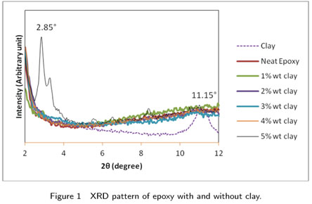
Figure 1 shows a typical result obtained from several XRD tests on samples of clay, neat epoxy and epoxy with dispersion of various wt. % clay. The results obtained are analyzed using Bragg's law to calculate the d-spacing.
As seen in most other papers [14,22] relative analysis of the peak and their intensity gives sufficient information to the degree of dispersion of these nanoclays in the resin. Fig. shows single peak at 11.15° and corresponding interlayer distance calculated from Bragg's law is 11.8 Å. It is observed that the basal reflection peak is absent up to 4% of clay. This reveals that the interlayer distance is more than 75 Å which means that Bragg's diffraction condition is not satisfied or exfoliated nanocomposite structure has formed [5]. For 5% clay, sharp reflection peak is noticed at 2.85° and corresponding interlayer distance is 46 Å which indicates that intercalated nano composites has formed. The formation of intercalated nanocomposite at 5% clay content is due to the un-even curing in the intergallery and extragallery matrix regions of the nanocomposites.
The tensile strength and tensile modulus for the laminates are given in the Table 1. The values are the average of five test specimens. Improvement of tensile strength of about 32% is noticed in laminates with 3% clay than laminates without clay. Similar improvement is reported in our earlier studies [13]. Similarly the improvements in tensile modulus is observed to be about 15% for laminate with 3% clay and about 10% for laminates with 4% and 5% clay.
2.2 Medium velocity impact
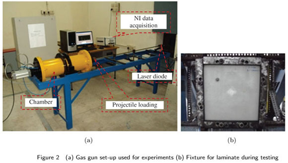
Prior to impact loading all the four edges of the laminates were clamped and the natural frequency and damping factor were obtained by impulse hammer technique. Figs. 2(a and b) show typical experimental set up used for the impact study. The specimens are subjected to impact loading. A steel cylindrical projectile with spherical nose of mass 7.6 g is used for impact loding at different velocities between 35 m/s and 82 m/s. Laser diode is used to record the incident velocity of the projectile. PCB accelerometer model PCB 352C41 of capacity of 500 g is used to measure the response through the data acquisition (DAQ) Card [NI-PXI 4472] and the response is recorded on the personal computer. The data acquisition system is used to capture the signal developed by the sensors.
2.3 Vibration test
Vibration tests based on impulse-frequency response method are used to find natural frequency and damping factor. The laminate is exited in vibration by an impulse hammer while specimen response is monitored by the accelerometer. The accelerometer location is identified in a non-damaged area by the projectile impact. The accelerometer is placed at 1/4 diagonal length which is also a non- nodal line. The hammer is exited near the projectile impact area. Excitation and response signals are fed into the Fast Fourier Transform (FFT) analyzer, which computes and displays the frequency response curve. Labview 8.6 program is used for this purpose. The series of the peaks in the frequency response curve give the natural frequencies of the system. The damping factor for the materials is obtained by using the half-power band width method (see, Figure 3).
The expression used to find the damping factor ξ, is

Where 1 and 2 are the lower and upper frequencies and n is the resonance frequency.
3 RESULTS AND DISCUSSION
3.1 Pre impact natural frequency and damping
The specimens are excited using the impulse excitation technique both before and after the impact. The natural frequencies of these tested laminates are obtained. The FRF plots are obtained from the NI-DAS and the peak values of these FRF plots provide the natural frequency of the laminates. Figures 4 to 9 show the experimental values of natural frequency and damping factor for the first five modes of vibration of laminates for clamped-clamped boundary condition. Improvement in natural frequency is noticed in all five modes of vibration due to nano filler dispersion. Fig. 4 shows modal natural frequencies for three layer laminates with and without clay content. First fundamental frequency of the laminate without clay is 138.2 Hz and the frequency increases as the clay percentage increases. For 5% clay content, the frequency is 155.6 Hz, i.e 12.6% increase in first fundamental frequency is noticed. At higher modes the difference in natural frequency is high. At fifth mode of vibration the difference between 5 % clay and without clay is 81 Hz, but the percentage of increase in natural frequency is same as in first mode. This is because of constant frequency ratio between the higher modal frequency and first mode frequency for the same geomentry and boundary condition of the laminates. Fig.5 shows modal natural damping factor for three layer laminates with and without clay content. The damping factor values are between 0.002 to 0.01 for laminates with and without clay for different modes of vibration. There is increase in damping factor values for addition of clay up to 3%, then there is drop in damping factor for all the modes. In mode I, there is 90% improvement in the laminate with 3% clay when compared with laminate without clay, and in mode V the improvement is about 130%. Presence of clay improves the damping factor and also this value is high in higher modes.
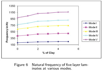
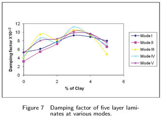
Fig. 6 shows the modal natural frequencies for five layer laminates with and without clay content. First fundamental frequency of the laminate without clay is 211.4 Hz and it increases as the clay percentage increases. For 5% clay content, the frequency is 248.8 Hz, i.e the increase is about 17.7%. At higher modes the difference in natural frequency between laminates with and without clay is still more. At fifth mode of vibration the difference between laminates with 5 % clay and without clay is 175 Hz, but the percentage increase in frequency is same for all modes which is similar to three layer laminates. Fig.7 shows damping factor of five layer laminates with and without clay content. It is observed, there is increase in damping factor values in laminates for clay up to 3% and then there is drop. For the first mode, there is 73% improvement and in mode V the improvement is about 90%.
Fig. 8 shows the modal natural frequencies of eight layer laminates with and without clay content. First fundamental frequency of the laminate without clay is 329 Hz and it increases as the clay percentage increases. For 5% clay content, the frequency is 362.5 Hz, i.e there is an increase of 10.1% in first natural frequency. At higher modes these difference in natural frequency are still higher. The trend of natural frequencies is similar to that of three layer and five layer laminates. Fig. 9 shows the variation of damping factors for the laminates with and without clay content. In eight layer laminates also, there is increase in damping factor values of clay up to 3% and then there is drop. In mode I, there is 65% improvement and in mode V the improvement is about 66%.
The improvement in frequency of vibration is due to the enhancement in modulus values of laminates with clay. In general it is observed that the addition of clay in the matrix increases the natural frequency of vibration due to increase in modulus of nano composites. Natural frequency increases for clay up to 3 wt%, and on further increase, the natural frequency remains same or slightly higher than laminates with 3% clay. At high clay content ( > 3%), the agglomeration and weak fibre - matrix interface are possible reasons for having not much increase in natural frequency.
It is clear that as the clay content increased, there is increase in damping factor which is due to the presence of the additional medium (clay) in the matrix. For rigid nano-particles, the high stress concentration area around the particles lead to initial microcracks and inelastic deformation in the matrix. The interfacial shear strength between nano-filler and matrix is higher than in conventional composites due to the formation of cross-links or shield the nano-fillers that form thicker interphases than in conventional composites.
Comparing both natural frequency and damping factor of these laminates, there is improvement in modal natural frequencies due to clay addition. In natural frequency, the improvement is noticed for clay up to 5%, but there is marginal difference in frequency for laminates with 4% and 5% clay content. Considering the damping factor, the improvement is noticed for laminates with clay up to 3%. The percentage of improvement is high for three layer laminates.
3.2 Post impacted natural frequency and damping factor
The test results for natural frequency of the laminates after impact are shown in Tables 2 to 4 for 3, 5 and 8 layered laminates, respectively. The Laminates with and without clay were subjected to impact velocity of 35, 50, 65 and 82 m/s. The natural frequency values corresponding to first five modes are obtained. It is observed that there is decrease in natural frequency of laminates with and without clay. The decrease in natural frequency is high in laminates when the velocity of impact is high. Also it is observed that the decrease in natural frequency is high at higher modes of vibration. But this decrease in natural frequency is less in laminates with clay.
Table 2 shows the post impact natural frequencies for three layer laminates with and without clay. Laminate with 1% clay subjected to 35m/s velocity shows 2.5% improvement in mode I and 2.2% in mode V. Similarly after 82m/s velocity, the improvement is 9.2% in mode I and 10.5% in mode V respectively. If laminates with 3% clay are compared with laminates without clay, the increase in natural frequency for 35m/s to 82m/s is from 9.2% to 19% in mode I and is 9.1% to 22.5% respectively in mode V. For laminates with 5% clay the increase in post impact natural frequency for 82m/s is 21.8% in mode I and 27.2% in mode V respectively. It is observed in post impacted specimens that there is increase in natural frequency for laminates with clay compared to laminates without clay. Also it is observed that as the percentage of clay is increased there is corresponding increase in percentage of natural frequency. This trend is seen for the velocities from 35m/s to 82m/s. The increase in natural frequency for laminates with clay is due to reduction in delamination compared to laminate without clay. Addition of clay improves the natural frequency and also it controls the delamination area in laminates subjected to impact loading (see, Fig. 10).
Table 3 shows the natural frequencies of post impacted five layered laminates with and without clay. In 1st mode, the natural frequency of laminate with 1% clay after the impact of 35 m/s velocity, is 222.1Hz and it is 6% higher when compared to laminate without clay. For the same laminate at mode V the post impact natural frequency is 975.9Hz and it is 5.8% higher than that of laminate without clay. In the case of laminates with clay of 5%, the increase in mode I and mode V natural frequencies are 15% and 17.5% respectively when compared to laminates without clay. Similarly for 82 m/s for the laminates with clay of 3% and 5% the increase in mode I natural frequencies are 24.2% and 26.6% respectively and for mode V the corresponding increase in frequency values are 28% and 31.8%. Hence it is understood that presence of nano clay increases the natural frequency and reduces the delamination area.
Table 4 shows the natural frequencies of post impacted eight layer laminates with and without clay. There is small increase (1.5%) in natural frequency of the laminates with 1% clay for 35 m/s velocity of impact in mode I and mode V when compared to laminates without clay. For the same laminate at 82 m/s velocity, the increase in natural frequency is 5.8% and 7% for mode I and mode V respectively. If we consider laminates with 3% clay the increase in natural frequency with reference to laminates without clay the range is from 8% to 12% in mode I and 8% to 15% in mode V for the velocities 35m/s to 82m/s. Similarly the range for 5% clay laminate is 10% to 15% in mode I and 10% to 18% in mode V. The reason for increase in frequency of laminates with nano clay is that the clay increases the stiffness of the specimen.
It is observed that as the velocity of impact increases the delamination area also increases and correspondingly there is decrease in natural frequency. Percentage of decrease in natural frequency at higher mode is higher than first mode. The percentage of decrease in natural frequency is high in laminates without clay. Hence it is clear that addition of clay controls reduction in delamination area which intern controls the reduction of natural frequency. Clay addition in thicker laminates improves reduction in natural frequency, this is because the control of delamination area by nano clay is high in thicker plates at high velocities. [see Figs. 11 and 12]. Figure 11 shows the variation in delamination area for 3 layer laminates subjected to impact velocities between 35m/s and 82 m/s. At velocity 35 m/s, the delamination size in the laminate without clay is about 78 sq. mm and no delamination is noticed in laminates with 4% and 5% nano clay. When the laminate is subjected to velocity of 82 m/s the delamination area for composite laminate without clay is 804 sq. mm. For the same velocity in laminates with 5% clay the delamination area is about 162 sq. mm. So, there is 80% decrease in delamination area due to clay addition. In all the laminates an increased delaminated area was observed on the rear side of the target than the front side which is due to bending of the target during impact. Fig. 12 shows that the reduction in delamination area due to nano clay is much higher in thick laminates than the thin laminates.
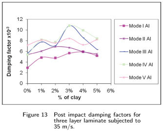
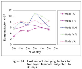
The damping factors of the impacted specimens are obtained by half power band width technique from FRF plot. The damping factor is obtained for the first five modes of the impacted laminates. Figs. 13 to 15 correspond to post impact damping factor values for 3, 5 and 8 layer laminates with and without clay, respectively. Fig. 13 shows the post impact damping factor values for three layer laminates when subjected to 35 m/s impact velocity. In mode I, the improvement for the laminate with 3% clay, is about 90% when compared to laminate without clay. For laminate with 5% clay the improvement percentage is about 75%. The same trend follows in other modes. Fig. 14 shows the post impact damping factor values of five layer laminates when subjected to 35 m/s. The improvement in damping factor for mode 1 is noticed due to clay dispersion in matrix. The percentage of improvement for 3% clay is about 63%. Similar improvement is observed in mode 2 to mode 5 of vibration. The post impact damping factors for 8 layer laminates are shown in Fig. 15. In mode 1, the improvement for laminate with 3% clay is about 57% and for 5% clay it is about 52%. It is observed that the presence of clay upto 3% improves the damping factor in all modes which is seen in pre impacted specimens also. Comparing 3, 5 and 8 layer laminates, the improvement percentage in damping factor is in high 3 layer laminates. This is due to higher delamination area of 3 layer laminates than 5 and 8 layer laminates, when subjected to impact loading. The improvement in damping factor of laminates with clay is due to clay dispersion in matrix and degree of delamination.
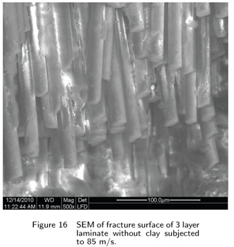
Figure 16 shows the fracture surface of epoxy-fiber composite without clay. It shows failure of bundle of fibers without any damage in the surface area as it is held by the matrix. There is no resistance from the matrix and hence the interfacial property of composite is poor and shows low strength. Figure 17 shows fracture surface of epoxy-glass fiber with 1% clay when subjected to 85 m/s. Failure of fibers are seen with non uniform length. It is also observed shear failure in fiber cross section as the failed cross section shows irregular shape. Figure 18 shows fracture surface of epoxy-glass fiber with 3% clay when subjected to 85 m/s. In this case, matrix at the surface of the laminates is completely damaged and fibers are not failed at impacted zone. The impact energy is absorbed by the matrix and crack in matrix is observed in the region away from the point of impact. Only few fibers are failed in the laminate with 3% clay nearer to impacted zone. This is because the energy is obsorbed by the matrix with nano clay and the clay has participated in the load sharing. Figure 19 shows fracture surface of epoxy-glass fiber with 5% clay when subjected to 85 m/s. Complete brittle failure of both fiber and matrix is observed. This is due to the aggolerimation of clay particles leading to weak bonding between the matrix and clay.
3.3 Comparision of frequency and damping factor for pre and post impacted laminates
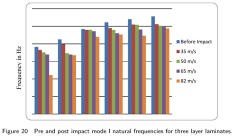
The experimental natural frequencies for pre and post impacted laminates are compared and the results for Mode I of three layer laminates are shown in Fig.20. In mode I, the natural frequency of laminate without clay, after 82 m/s velocity of impact, is 11.6% less compared to pre impacted specimens. In mode V the natural frequency is about 19% less when compared to pre impacted specimens. For the same velocity, the laminates with clay of 1% to 5% the decrease in mode I natural frequency is between 6.32%to 2.96%. Similarly for mode V, the decrease in natural frequency after the impact is between 13.13% to 8.46%.
Fig. 21 shows the comparision of natural frequencies between pre and post impacted five layer laminates with and without clay which were subjected to impact loading. In mode I, the natural frequency of laminate without clay after the impact of 82 m/s velocity is 9.27% less compared to pre impacted specimen. For the same laminate at mode V after the impact of 82 m/s, the natural frequency is about 17% less compared to the pre impact specimen. If we consider the laminates with clay of 1% to 5%, the decrease in mode I natural frequency is less than 4%. Similarly for mode V, the decrease in natural frequency is between 9.3% to 6.5%.
Fig. 22 shows the comparison of frequencies corresponding pre and post impacted eight layered laminates with and without clay. For mode I, the natural frequency of laminates without clay after 35m/s velocity of impact is 5.3% less compared to the value of pre impacted specimen. At 82 m/s, the natural frequency is about 13% less compared to the value of pre impacted specimen. If we consider laminates with clay of 1% to 5%, the decrease in mode I natural frequency is less than 2%. Similarly for mode V, the decrease in natural frequency after impacted is less than 10% when compared to the value of pre impacted specimens.
It is to be understood that as the impact velocity increases the delamination area increases which intern reduces the natural frequency of the laminate. Addition of clay improves the natural frequency and also it controls the delamination area in laminates subjected to impact loading. Hence the decrease in frequency of laminates with clay subjected to impact loading is much less than that in laminates without clay.
Figures 23-25 correspond to Mode I damping factor values for 3, 5 and 8 layer laminates with and without clay respectively. It is seen that there is improvement in damping factor for laminates with clay upto 3%. It is observed in laminates with clay that as the velocity of impact increases the increase in damping factor is almost double. This is because, the damping factor is improved by nano clay as well as by the delamination area. In laminates with clay between 1% to 5%, the maximum increase in damping factor is in laminates with 3% clay and difference in damping factor with increase of impact velocity is much less when compared to laminate without clay. The reason being that the clay controls the delamination due to which the increase in damping factor is less for the velocity of impact increases. But in laminates without clay the increase in damping factor with increase of impact velocity is high as the delamination area increases with increase of impact velocity.


4 CONCLUSION
Composite laminates were prepared by hand lay-up and compression molding process and subjected to projectile impact for velocities between 35m/s and 82 m/s in clamped-clamped boundary condition. The natural frequency and damping factor of the laminates are obtained before and after impact. The following conclusions are made.
1. XRD pattern of nano composites shows no peaks which ensures the uniform dispersion of clay in the resin for clay upto 4%.
2. Natural frequency and damping factor in laminates are improved due to the presence of nano clay.
3. The natural frequency for the impacted specimen is less that in pre impacted specimen which is due to the damage caused by impact.
4. The damping factor and delamination area increase with increase of impact velocity.
5. In composites with clay the delamination area decreases with the increase of clay content and is seen for all velocity ranges. Due to this the increase in damping factor is less than that in laminates without clay.
6. Dispersion of clay improves the energy absorption capacity of matrix and protects failure of fiber.
Acknowledgement
The authors gratefully acknowledge the support of the Aeronautical Research and Development Board, Structures panel, India.
Received 31 Aug 2010
In revised form 2 Feb 2011
- [1] R.D. Adams and M.R. Maheri. Dynamic flexural properties of anisotropic fibrous composite beams. Composite Science Technology, 50(4):497514, 1994.
- [2] A. Avila, H.V. Duarte, and M.I. Soares. The nanoclay influence on impact response of laminated plates. Latin American Journal of Solids and Structures, 3:320, 2006.
- [3] A. Avila, M.I. Soares, and A.S. Neto. A study on nano structured laminated plates behaviour under low-velocity impact loadings. International Journal of Impact Engineering, 24:2841, 2007.
- [4] J.M. Berthelot. Damping analysis of laminated beams and plates using the ritz method. Composite Structure, 74:186201, 2006.
- [5] K.A. Carrado. Synthetic organo- and polymer-clays: preparation, characterization and materials applications. Applied Clay Sciences, 17:123, 2000.
- [6] R. Chandra, S.P. Singh, and K. Gupta. Damping studies in fiber-reinforced composites-a review. Composite Structure, 46:4151, 1999.
- [7] J. Chandradass, M. Ramesh kumar, and R. Velmurugan. Effect of nanoclay addition on vibration properties of glass fiber reinforced vinyl ester composites. Materials letter, 61:43854388, 2007.
- [8] C.N. Della and D. Shu. Vibration of delaminated composite laminates: A review. Applied Mechanics Reviews, 60:120, 2007.
- [9] J. Gou, S. O'Briant, H. Gu, and G. Song. Damping augmentation of nano composites using carbon nano fiber paper. Journal of nano materials, pages 17, 2006.
- [10] M. Kireitseu, D. Hui, and G. Tomlinson. Advanced shock-resistant and vibration damping of nano particle-reinforced composite material. Composite: Part B, 39:128138, 2008.
- [11] A. W. Leissa. Vibration of plates. Technical Report NASA SP-160, Scientific and Technical Information Division of NASA, Washington, 1969.
- [12] A.E.I. Mahi, M. Assarar, Y. Sefrani, and J.M. Berthelot. Damping analysis of orthotropic composite materials and laminates. Composites: Part B, 39:10691076, 2008.
- [13] T.P. Mohan, M. RameshKumar, and R. Velmurugan. Mechanical, thermal and vibration characteristics of epoxy-clay nano composites. Journal of Materials Science, 41(18):59155925, 2006.
- [14] T.P. Mohan and R. Velmurugan. Epoxy clay nano composites and hybrids synthesis and characterization. Int. Journal of Reinforced Plastics and composites, 28:1737, 2009.
- [15] P.M. Mujumdar and S. Suryanarayan. Flexural vibrations of beams with delaminations. Journal of Sound Vibrations, 125:441461, 1988.
- [16] R.G. Ni and R.D. Adams. The damping and dynamic moduli of symmetric laminated composite beams theoretical and experimental results. Journal of Compos Materials, 18(2):104121, 1984.
- [17] Y. Ohta, Y. Narita, and K. Nagasaki. On the damping analysis of FRP laminated composite plates. Composite Structure, 57:169175, 2002.
- [18] R.K. Patel, B. Bhattacharya, and S. Basu. Effect of interphase properties on the damping response of polymer nano-composites. Mechanics research communications, 35:115125, 2008.
- [19] L. Roland, R. Woodcock, B. Bhat, and I.G. Stiharu. Effect of ply orientation on the in-plane vibration of single layer composite plates. Journal of sound and vibrations, 312:94108, 2008.
- [20] A. Shahdin, J. Morlier, and Y. Gourinat. Significance of low energy impact damage on modal parameters of composite beams by design of experiments. Journal of Physics: Conference Series, 181:1245, 2009.
- [21] S.A. Suarez, C.T. Sun R.F. Gibson, and S.K. Chaturvedi. The influence of fiber length and fiber orientation on damping and stiffness of polymer composite materials. Experimental Mechanics, pages 175184, 1986.
- [22] T.B. Tolle and D.P. Anderson. Morphology development in layered silicate thermoset nanocomposites. Compos Science Technology, 62:10331041, 2002.
- [23] U.K. Vaidya, S. Pillay, S. Bartus, C. A. Ulven, D.T. Grow, and B. Mathew. Impact and post-impact vibration response of protective metal foam composite sandwich plates. Material Science and Engineering A, 428:5966, 2006.
- [24] J.H. Yim and J.W. Gillespie Jr. Damping characteristics of 0ş and 90ş as4/3501-6 unidirectional laminates including the transverse shear effect. Composite Structure, 50:217225, 2000.
Publication Dates
-
Publication in this collection
01 July 2011 -
Date of issue
2011
History
-
Received
31 Aug 2010 -
Reviewed
02 Feb 2011