Abstract
In this research, finite element and boundary element methods are coupled together to model the interaction of a piezoelectric ceramic working as an actuator with an elastic material. Piezoelectric-elastic material's interaction occurs in smart structures. This work is aimed at determining the actuation effects being transferred from the actuators to the host and the resulting overall structural response. To obtain the amount of these actuations, the system of the host structure and an actuator has been modeled by using coupled finite element boundary element method in frequency domain. The host structure, which is assumed as an isotropic elastic solid region is modeled as a half space. The piezoelectric ceramic region is modeled by the 3-D finite element method, while the elastic half space with boundary element method. Finite element model of piezoelectric ceramic and boundary element model of the elastic half space are coupled together at their interface such that the vibrations of the piezo-actuator induce vibrations in the elastic half space. A couple of examples are given to show the induced displacement field around the piezo-actuator on the surface of the elastic medium. The results show that high jump in magnitude of horizontal displacements at the corners of the actuator attached to the structure occurs, which is an indication of high stress concentration, of the shear stress type at the corners. This stress concentration sometimes causes complete debonding of the actuator from the base structure. By using the suggested BEM-FEM coupled model for actuators with different dimensions or material properties much useful information concerning the amount of actuation and load transfer can be obtained. The presented work is a step towards modeling of structural health monitoring systems.
finite element; boundary element; piezoelectric ceramic; elastic half space; smart structure; actuators; stress concentration
A FEM-BEM interactive coupling for modeling the piezoelectric health monitoring systems
Abid A. Shah* * Author email: abishah@ksu.edu.sa
Specially Units for Safety and Preservation of Structures, College of Engineering, King Saud University, P. O. Box 800, Riyadh 11421 Saudi Arabia
ABSTRACT
In this research, finite element and boundary element methods are coupled together to model the interaction of a piezoelectric ceramic working as an actuator with an elastic material. Piezoelectric-elastic material's interaction occurs in smart structures. This work is aimed at determining the actuation effects being transferred from the actuators to the host and the resulting overall structural response. To obtain the amount of these actuations, the system of the host structure and an actuator has been modeled by using coupled finite element boundary element method in frequency domain. The host structure, which is assumed as an isotropic elastic solid region is modeled as a half space. The piezoelectric ceramic region is modeled by the 3-D finite element method, while the elastic half space with boundary element method. Finite element model of piezoelectric ceramic and boundary element model of the elastic half space are coupled together at their interface such that the vibrations of the piezo-actuator induce vibrations in the elastic half space. A couple of examples are given to show the induced displacement field around the piezo-actuator on the surface of the elastic medium. The results show that high jump in magnitude of horizontal displacements at the corners of the actuator attached to the structure occurs, which is an indication of high stress concentration, of the shear stress type at the corners. This stress concentration sometimes causes complete debonding of the actuator from the base structure. By using the suggested BEM-FEM coupled model for actuators with different dimensions or material properties much useful information concerning the amount of actuation and load transfer can be obtained. The presented work is a step towards modeling of structural health monitoring systems.
Keywords: finite element, boundary element, piezoelectric ceramic, elastic half space, smart structure, actuators, stress concentration.
1 INTRODUCTION
Health monitoring of the existing structures or materials is an issue of critical relevance in many civil, mechanical, chemical, aeronautic and aerospace engineering applications. In some of these cases conventional non-destructive evaluation methods are effective; however for some, those methods are in-effective. A bulky mechanical structure cannot be taken to the laboratory every time to check its body for unwanted displacements or damages initiated by small cracks and even if it is possible, how often we can check the bodies of such structure to make sure the system is healthy and there is no damage at all?
In recent years, structural health monitoring (SHM) has emerged as a concept in the broader field of investigation of smart structures [1, 53]. Structural systems are usually described as smart when they are able to sense and adapt their response to changing operational or environmental conditions. Their development relies on the integration of sensors and actuators with the structure and on the combination with appropriate electronics, modeling and control algorithms. SHM systems exploit such features to detect the occurrence and location of damage which may affect the performance and reliability of the structure. While conventional non-destructive inspection procedures investigate directly for damage at scheduled intervals applying the appropriate technique, in situ SHM systems are generally based on the real time comparison of the local or global response of the damaged structure with the known response of the undamaged one.
In piezoelectric structural usage and health monitoring systems, the monitoring is performed through a network of suitably arranged piezoelectric sensors, some physical variables and fields, such as strain, vibration, electrical conductivity and acoustic emission, which may be affected by the changes of material and geometrical conditions in proximity of the damaged area. This system has an advantage of the direct piezoelectric effect, which refers to the generation of an electric displacement field as a consequence of a mechanical load. As a result it is able to sense structural deformation and signal it through a variation of voltage or rate of variation of voltage [16].
Piezoelectric materials are among the most widely used smart materials because of their reliability and sensitivity [43]. Their common use as sensors/actuators in smart structures is also due to their fast response and low energy consumption [21]. Piezoelectric sensors for SHM applications are usually employed in the form of small polyvinylidene fluoride (PVDF) patches or thin lead zirconate titanate (PZT) monolithic wafers. While PVDF elements are mainly used for sensing applications, stiffer PZT transducers can also be used for actuation purposes. They can be bonded on the surface of the structure or embedded into the structure itself and allow the determination of local values of strains. Due to their small sizes, the gradient identification for damage detection applications is often based on the use of arrays of such micro-electromechanical systems (MEMS).
A piezoelectric actuator usually consists of two main components [35]: a mechanical part, which is a flexible structure, and an electrical part, which is the piezoelectric material block. One of the important issues of using piezoelectric actuator is to improve their performance for a certain amount of piezoelectric material, which is the goal of piezoelectric actuator design. Since the mechanical part of flextensional actuators is actually a compliant mechanism, piezoelectric transducer [41] and thermal actuators [41, 63] have been also designed using topology optimization technique. This topological design optimization was able to generate effective mechanical structure that greatly improved the performances of the piezoelectric actuator.
Piezoelectric actuator has been increasingly used in MEMS system due to its advantage of generality and flexibility. A flextensional actuator consists of a piezoceramic device, which can convert electrical energy into mechanical energy and vice versa, and a flexible mechanical structure, which can convert and amplify the output piezoceramic displacement in the desired direction and magnitude [62]. A recent research in this area is optimizing the topology of the mechanical part while fixing the electrical part [64]. There have also been design optimization techniques developed for the electrical part of piezoelectric actuator. The placement and size of piezo-material was optimized [47]. In a recent research, the distribution of piezoelectric material in the optical MEMS was optimized [25].
The optimal design of piezoelectric actuators and sensors has been an interesting research subject in recent years as may be seen in a review paper [24]. Researchers are focusing on every aspect and every component in order to achieve the best performances, from piezoceramic composite design, optimal sizing and locating to topology optimization [36]. Topology optimization with homogenization method was proposed by [8] to design the stiffest structure. This method is then applied to design compliant mechanisms and composite materials [49].
Additional, existing research in this area may be divided into two categories: the optimal placement of actuators with or without the optimization of controller parameters for predetermined structures [2, 26, 28, 29, 55, 65] and the optimization of actuators and surrounding structures [14, 22, 38]. To maximize the stroke displacement of a piezoelectric actuator based on the compliant mechanism, the topology optimization method (see, e.g., [8]) has been used as an efficient design tool [14, 38]. As far as the topology optimization is concerned, some investigations are focused mainly on the optimization of base structures made of passive non-piezoelectric materials where the piezoelectric elements serve only as driving sources. Other investigations are focused on piezoelectric material parts possibly in conjunction with non-piezoelectric material parts.
Because of their importance in deformation and vibration control of flexible structures, the modeling of plate and thin sheet actuators in smart structures had received significant attention [19]. In the research [54] a beam-like structure with surface bonded or embedded thin sheet piezoelectric actuators was analyzed to study the stresses transmitted by the actuators to the host beam. In that analysis, the axial normal stress in the actuator was assumed to be uniform across its thickness and the host was modeled as a Bernoulli-Euler beam. By ignoring the inertial effect of the actuator, the result indicated that, for a perfectly bonded actuator, the shear stress between the actuator and the host was transferred over an infinitesima1 distance near the ends of the actuator, i.e., the entire shear force is transferred at the two ends of the piezoelectric actuator. Since no structural force other than a pure bending moment upon the cross section of beam was considered, this model did not account for the effect of the transverse shear which was exerted on the beam by the piezo-actuator. This model is often referred to as Pin-force model [15, 54] or the uniform strain model [40].
Crawley and Anderson [18] developed a Bernoulli-Euler model of a piezoelectric actuator by considering the linear stress distribution along its thickness to describe the actuation effect on the host beam. To assess the accuracy of these models, the structural response of a beam with piezoelectric actuators using the uniform strain model and Bemoulli-Euler rod was calculated by [18]. By comparing the prediction of these models with finite element solutions and experimental measurements of the surface strains from substructure and actuator, they concluded that the Bernoulli-Euler model is more accurate than the uniform strain model. The earlier actuator model presented by [54] was modified by [32] to investigate a beam with a piezoelectric actuator under general loading. Both the axial force and the transverse shear force in the beam were considered in formulating the governing equations of the problem. It was found that the axial force in the beam had a significant effect on the shear stress transmitted from the actuator to the host.
A refined actuator model based on the plane stress formulation of the theory of elasticity was presented for a beam structure with symmetrically surface-bonded actuator patches [42]. The stress distribution in the actuators and the host beam was determined by using an approximated axial normal stress field with a parabolic profile in the direction of the thickness of the actuator. It was then concluded, by comparing with the finite element results, that this model captured the attenuation of the effective force/moment near the actuator edges, and was in good agreement with the finite element results, except in the region about one actuator thickness from the actuator edges. A plate and shell model was also used to model piezoelectric structures by modifying the classical laminated plate theory for static loading [60].
Because of the approximation made in analytical modeling explained above, inertial effects and singularities were ignored. In most of the theoretical investigations as stated above, classical beam and plate theories were used to model the deformation of the host structure. This results in zero transverse of shear stress across the actuator/host interface, except for the ends of the actuator. Physically, the assumption of a linear strain distribution through the thickness of a substrate material undergoing induced strain actuation from piezoelectric actuators seems oversimplified as far as the local stress level is concerned [51]. This had motivated the usage of numerical methods to investigate the local stress distribution around an actuator and the load transfer between the actuator and the host. Kulkarni and Hanagud [39] extended the variational formulation of Tiersten [57, 58] and presented a two dimensional finite element formulation for the problem of an elastic body with bonded piezoelectric actuators subjected to different electromechanical loadings. The problem of a cantilever beam with one top and one bottom piezoelectric actuators was also investigated in details for different applied electric loads. Although the axial strain distribution at the central part of the actuator/host interface agreed well with the prediction of the uniform strain model [40], the interfacial shear stress was found to be very high at and near the actuator ends.
The stress distribution of the bonded surfaces of embedded and surface mounted piezoelectric actuators was further investigated by [52] using the finite element formulations. It was found that the tractions at the actuator/host interface were concentrated towards the edge of the surface mounted piezoelectric actuator and therefore a small bonded area was used for load transfer. There is very high stress gradient near the edge of the actuator and fifty percent of the resultant force is transferred by approximately 10-20 percent of the interface near the edge. The embedded piezoelectric transferred a smaller load, through this component of the traction and the variation over the surface is also small. The resultant force transferred in the thickness direction is concentrated towards the edge in both cases. However, singularity appears at the edge in the case of the surface bonded piezoelectric. Comparison between embedded and surface mounted actuators indicated that the stress concentration is less severe at the corners of an embedded actuator.
Further in regard of the above explanation, it is also well known that analytical solutions can be obtained only for the simple cases. However, for piezoelectric actuators used in engineering applications, it is very difficult to obtain the closed form solution of the local electro-elastic field. For obtaining solutions in general complicated cases, therefore, numerical methods, such as the hybrid finite element method, boundary element method, and/or the coupled FEM BEM are used. Details on the modeling of piezoelectric materials and smart structures by conventional finite elements and boundary element methods may be referred as [10, 20, 45].
With reference to the research in [46], for modeling of sensors and actuators frequently boundary element method (BEM) based formulations have to be coupled with finite element method (FEM) formulations. Because each method performs better than the other in some domains or some parts of the same domain. Therefore, a combined approach could be both accurate and efficient for a large class of problems. For example, problems with high stress gradient regions could be modeled using BEM while FEM could be used for the rest of the structure. Zhang et al. [66] analyzed the problem of a piezoelectric layer bonded to an elastic substrate, considering the full coupling between electrical and mechanical fields. Ali et al. [3] developed an analytical model for constrained piezoelectric thin film sensors and applied the model to the analysis of the problem of detection of subsurface cracks [4]. An analytical solution for the coupled electromechanical dynamic behavior of a piezoelectric actuator bonded to an infinite orthotropic elastic medium has been developed by Huang and Sun [30]. The earlier efforts at integrating boundary elements and finite elements have been problematic and inefficient due to the unsymmetrical nature of the boundary element method. This process becomes even more cumbersome in a typical assembly process. When the different parts of a structure are modeled independently of each other in a sub-domain format, it is important to keep account of the fact that the nodes at the interfaces match exactly [12, 23, 33]. Additionally, for the cases where the piezoelectric device is very small relative to the host structure, finite element is not a very effective numerical tool and usually the required grid numbers are too large that it is not economical anymore.
This paper is concerned with the development of a three dimensional numerical model for the dynamic interaction of a piezoelectric ceramic bonded on the surface of a semi-infinite elastic domain. In this numerical technique finite element method is implemented for the modeling of the piezo-actuator and boundary element method for the semi-infinite isotropic elastic domain. The model considers dynamic interaction of the two materials in frequency domain. This method is usually used to solve the problems which deal with sort of coupling or interaction of two media because both FEM and BEM are very powerful numerical tools the coupling of which have the advantage of modeling the complex piezoelectric materials economically and reliably.
2 RESEARCH SIGNIFICANCE AND PLAN
Finite element has been used as a numerical tool to model piezoelectric electromechanical coupling [9, 34, 67]. However, it is very costly to model a crack/defect or the complexity involved in piezoelectric electromechanical coupling by using only finite elements. Recently, it is demonstrated that hybrid finite element and boundary element formulations have the advantages of high accuracy to model the smart structures and piezoelectric materials for computing edge singularities [56]. For this sort of problems a combination of finite element and boundary element is usually very effective and reliable since finite element method is especially suitable when we are dealing with finite structures with some sort of complexities like piezoelectric ceramic. While boundary element method is well suited for infinite domains, reducing the dimension and simplifying the modeling considerably because of its boundary only approach. It is also useful for a wide range of problems such as structural, acoustics, elastodynamics and fluid analysis problems. Additionally, BEM is particularly good for problems that have singular or near singular behavior within the domain. In view of this, it is possible that different parts of a structure are modeled independently by BEM and FEM methods and then coupled together to solve the problem exploiting the advantages of both. In this case, the usefulness of the combined approach, though limited, is obvious. This paper is, therefore, aimed at using hybrid method that couples nodes of FEM and BEM to model the piezoelectric ceramics and exploits the potential of each approach. The presented work can be very advantageous for many types of problems dealing with modeling of structural health monitoring systems.
The present work is organized as follows. The piezoelectric materials and modeling are first described. The basic concept of piezoelectricity is reviewed and preliminary equations are stated. In the next section finite element modeling of piezoelectric materials is explained. Both static and dynamic modeling of piezoelectric materials by finite element method is discussed. Some numerical examples are then solved and the results are compared with the similar examples in other studies to show the accuracy of the developed FEM code. In Section 5 the concept of boundary element method for the elastic solid is briefly reviewed and the main features of the hierarchical format are revised. Section 6 introduces the idea of coupling of finite element and boundary element methods, its history perspective and different coupling approaches. Additionally, the approach used in this research is also explained. In Section 7 the model for the structure with attached piezoelectric patches is introduced. Several numerical applications are performed by the developed FEM-BEM code while the results obtained are presented in the form of graphs and discussed. Section 8 includes the conclusions and judgments made to illustrate the potential use of the developed FEM-BEM code for design of SHM systems.
3 THEORY OF PIEZOELECTRICITY
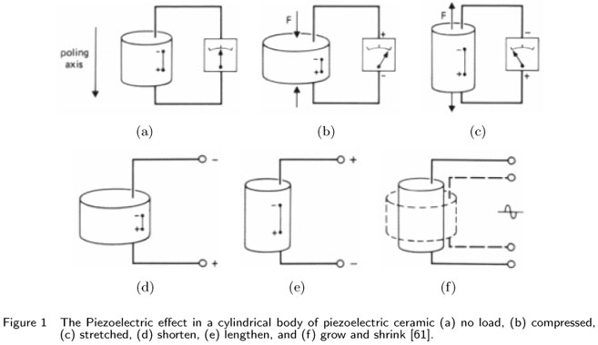
Some material usually ceramics have a property called piezoelectricity [6]. If stress is applied to such material, it will develop an electric moment proportional to the applied stress. This is the direct piezoelectric effect. Conversely, if it is placed in an electric field, a piezoelectric material changes its shape slightly. This is the inverse piezoelectric effect. Fig. 1 shows this property in a cylindrical piezoelectric material.
Piezoelectric materials are the piezoelectric ceramics, of which PZT is an example. These are polycrystalline ferroelectric materials with the perovskite crystal structure-a tetragonal/rhombahedral structure very close to cubic. The composition, shape, and dimensions of a piezoelectric ceramic element can also be modified to meet the requirements of a specific purpose. Ceramics manufactured from lead zirconate/lead titanate group exhibit greater sensitivity and higher operating temperatures, relative to ceramics of other compositions.
PZT materials currently are the most widely used piezoelectric ceramics. They can be considered as a mass of minute crystallites. Above a temperature known as the Curie point, these crystallites exhibit simple cubic symmetry, with positive and negative charge sites coinciding. Therefore, there are no dipoles present in the material (which is said to exhibit paraelectric behaviour). Below the Curie point, however, the crystallites take on tetragonal symmetry in which the positive and negative charge sites no longer coincide, so each elementary cell then has a built-in electric dipole which may be reversed, and also switched to certain allowed directions by the application of an electric field. Such materials are termed ferroelectric because this electrical behaviour presents a physical analogy with the magnetic behaviour of ferromagnetic materials.
The dipoles are not randomly oriented throughout the material. Neighbouring dipoles align with each other to form regions of local alignment known as Weiss domains. Within a Weiss domain, therefore, all the dipoles are aligned, giving a net dipole moment to the domain, and hence a net polarization (dipole moment per unit volume).
The direction of polarization between neighbouring Weiss domains within a crystallite can differ by 90º or 180º , and owing to the random distribution of Weiss domains throughout the material (Fig. 2 (a)), no overall polarization or piezoelectric effect is exhibited. The ceramic may be made piezoelectric in any chosen direction by a poling treatment which involves exposing it to a strong electric field at a temperature slightly below the Curie point (Fig. 2 (b)).
Under the action of this field, domains most nearly aligned with the field will grow at the expense of other domains. The material will also lengthen in the direction of the field. When the field is removed (Fig. 2 (c)), the dipoles remain locked in approximate alignment, giving the ceramic material a remanent polarization and a permanent deformation (i.e. making it anisotropic). The poling treatment is usually the final treatment of PZT component manufacture.
Although the magnitudes of piezoelectric voltages, movements or forces are small and often require amplification, piezoelectric materials have been adapted to an impressive range of applications. The piezoelectric effect is used in sensing applications, such as in motors and devices that precisely control positioning, and in generating sonic and ultrasonic signals. A piezoelectric system can be used almost instead of any other type of electromechanical transducer. Piezoceramic devices fit into four general categories: generators, sensors, actuators, and transducers.
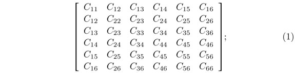
From the view point of elasticity, the difference in an ordinary material and a piezoelectric ceramics can be best explained as follows [31]. All the material properties that affect the stress or strain of an ordinary material can be represented by the elasticity matrix which is a symmetric 6 x 6 matrix as follows,
However, in piezoelectric material electric potentials or charges can affect mechanical stress or strain too. This behavior depends on the values of the piezoelectric constants. Because a piezoelectric ceramic is anisotropic, physical constants relate to both the direction of the applied mechanical or electric force and the directions perpendicular to the applied force. Consequently, each constant generally has two subscripts that indicate the directions of the two related quantities, such as stress and strain for elasticity. The direction of positive polarization usually is made to coincide with the Z-axis of a rectangular system of X, Y, and Z axes. Directions X, Y, or Z are represented by the subscript 1, 2, or 3, respectively, and shear about one of these axes is represented by the subscript 4, 5, or 6, respectively [31].
4 FINITE ELEMENT MODEL FOR PIEZOELECTRIC MATERIALS
The constitutive equations of the piezoelectric materials are given by
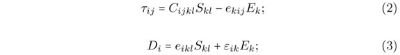
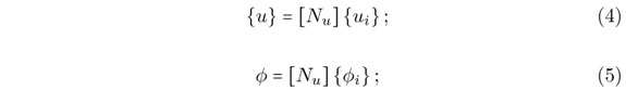
where C is the elasticity matrix for constant strain, ε is the matrix of dielectric constants for constant mechanical strain, e is matrix of piezoelectric constants, and τ, S, E and D are vectors of stress, strain, electric field and electric displacement, respectively. In the finite element formulation, the displacement field {u} and the electric potential ϕ over an element are related to the corresponding node values ui and {ϕi} by the means of the shape functions [Nu], and [Nϕ], as indicated by equations (4) and (5).
Therefore, the strain field {S} and the electric field {E} are related to the nodal displacements and potentials by the shape functions derivatives [Bu] and [Bϕ] defined by
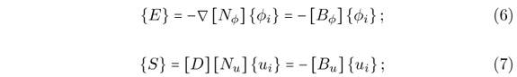
where ∇ is the gradient operator and D is the derivation operator defined as

and {ui}={ux1uy1uz1ux2uy2uz2 ... ux20uy20uz20} is the vector of nodal displacements for 20-node quadratic three dimensional element as shown in Fig. 3 [7, 17], which is used in this model and ϕ ={ϕ1ϕ2 ... ϕ20} is the vector of nodal electric potentials for 20-node quadratic three dimensional element.
Allik and Hughes [5] developed the finite element method for a piezoelectric material in the form of equation (8) in frequency domain

In which,
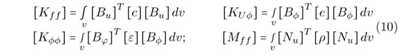
where, F is the mechanical force, Q is the electric charges, r is the mass density of the material. The finite elements system of equations for the whole FEM domain is assembled by considering the finite element equation for each of the elements in the finite element mesh.
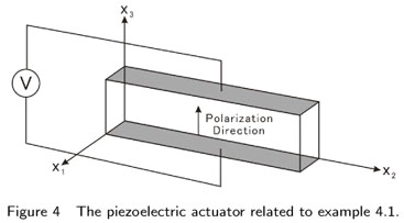
4.1 Typical example to verify the finite element code (single layer longitudinal d33 motor or actuator)
A single layer actuator is modeled and the results for deflection are compared to exact solutions to verify the Finite Element code. The dimensions of the actuator in x1, x2, and x3 directions are 0.02, 0.1, and 0.04 m, respectively. The geometry of the problem is given in Fig. 4.
The actuator is made of PZT4 whose corresponding nonzero material constants are as follows,
The finite element three dimensional mesh consists of eight elements; One element along x1 direction, four elements along x2 direction and two elements along x3 direction.
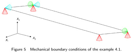
The mechanical boundary conditions are chosen such that the actuator is free to move in any direction and at the same time the structure remains statically stable. These mechanical boundary conditions are shown in the Fig. 5. In that figure, the blue supports are the supports in x1 direction, the green supports are the supports in x2 direction and the red supports are the supports in the x3 direction.
The actuator is connected to the electric potential of one volt on the top surface and the bottom surface is grounded .Moreover no electric charges is associated to the nodes inside the piezoelectric [27, 48]. The results obtained from the Finite Element code for the expansion in the thickness direction is Z = −0.2888088 ×10⁻⁹ m and from the exact solution is Z = −0.2888088 ×10⁻⁹ which shows a very good agreement.
For the contraction in the transverse direction the Finite Element Code gives the transverse contraction of X = 6.130715 ×10−11 at x1 direction and Y = 3.065358 ×10−10 at x2 direction. The exact solutions are calculated using the following equations,
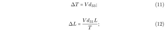
where ΔT is the amount of displacement in thickness direction, V is the electric potential d33, d31 are the piezoelectric strain constants, ΔL is the amount of displacement in length direction and L is the dimension of piezoelectric in the length direction.
From Eqs. (11) and (12), therefore
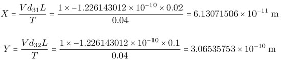
which again shows a very good agreement with the results of FEM code.
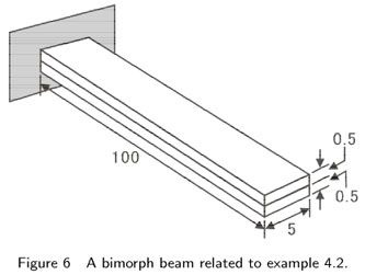
4.2 A parallel bimorph beam
A parallel bimorph beam, made of two layers of piezoelectric polymetric polyvinylidene fluoride (PVDF) with the same polarities is connected to the voltage source of one volt in a parallel connection. The material properties of PVDF are as follows,
The geometry of the problem has been shown in Fig. 6. The dimensions are in millimeter.
To model the bimorph beam with Finite Element, two different models were used. The first one is a mesh consists of one element along the width direction, two elements along the length direction and two elements along the height direction or totally four elements and the second one consists of one element along the width direction, four elements along the length direction and two elements along the height direction or totally eight elements.
The deflection at different distances from the fixed end of the beam for these two different models were calculated and compared with the exact solution of Eqs. (11) and (12). The result of this comparison is tabulated in Table 1.
From the Table 1, we can observe that by increasing the number of elements or using smaller mesh, FEM results converge to the exact solution. Also according to Table 1, error ratio around the fixed end of the beam is more than at the free end and as we approach to the free end of the beam the trend is clearly noticeable. The reason of this behavior is that the discritized finite element is relatively rigid near the fixed end. The model can be improved by using more elements [59]. Figs. 7 (a) and 7 (b) also show the distribution of displacement in the bimorph beam for two opposite direction of electric potential of one volt. The figures indicate that opposite direction of electric potential produces opposite direction of bending in the bimorph beam.
5 BOUNDARY ELEMENT FORMULATION FOR AN ELASTIC SOLID
Consider an elastic body Ω which has the boundary Γ and the unit normal to this boundary is n as shown in Fig. 8. In boundary element method (BEM) [13], for frequency domain elastodynamics, we establish a relationship between the values of the displacements and the surface tractions on the boundary Γ. To do so a numerical integration has to be done over the boundary Γ.
The fundamental equation in the elastodynamics BEM is known as Somigliana's identity [37]. In this equation the weighting functions are the fundamental solution, which satisfies the Sommerfeld radiation condition.
Eq. (13) shows the displacement fundamental solution for an elastic, homogeneous and isotropic continuum in frequency domains for infinite medium.
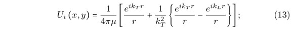
where ks, kp are shear wave number and pressure wave number, respectively and r is the distance between the source point y and the field point x.
The fundamental solution for traction ( ) is obtained by taking the dot product between the stress fundamental solution tensor and the unit outward normal vector, as follows

where  is the fundamental solution for stress and it is calculated from the displacement fundamental solution through the following relationship.

where r,i is the derivative of r with respect to x and r,i is the derivative of r with respect to y.
For BEM integral formulation in frequency domain, if we consider two elastodynamics states over the body Ω and displacement, traction and body forces respectively are shown by  , and
, and  for the two states. Considering Betti Reciprocal Theorem, the following relationship may be formulated between the two states.

Taking as the state of real, physical displacements, tractions and body forces, and assuming that the second state corresponds to the fundamental solution, Eq. (16) changes to Eq. (17):

Using  (x, ω; y) = (y, ω; x), by substituting i by l, and x by y we can rewrite Eq. (17) as,

This equation holds for any observation point x which is interior to the domain.
If there are no body forces then the integral equation for a point on the surface may be derived from Eq. (18) as,

where, U* is the displacement fundamental solution, P* is the traction fundamental solution, U is the displacement, P is the traction, C is a parameter which depends on the geometry of the boundary. Eq. (19) is called somigliana identity and forms the mathematical basis for the direct boundary integral and boundary element methods.
The tensor Cil(x) depends on the geometry of the boundary Cil(x) = 1/(2δil), if the surface is smooth at x. For any other configuration of the surface geometry at the observation point, other values of Cil(x) are used.
Replacing Eq. (19) in the Eq. (18) the discretized boundary integral equation, i.e. the BEM formulation for a single collocation node with the coordinate x is obtained from the Eq. (20):
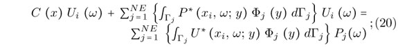
where NE is the number of boundary elements in the domain. Ui(ω)are the complex amplitude of displacement at xi.
The N matrix equations for each of the collocation nodes in the BE domain may all be assembled into a single, global matrix equation for the entire domain [11] as

which is the matrix form of Eq. (20):
The  matrix has nonzero values only on the diagonal for smooth surface boundaries.
  and G are the values of the integrals over the fundamental solutions for the traction and displacement, respectively and U and P are vectors storing the displacements and tractions at each node and for each degree of freedom respectively. Therefore for a three dimensional problem like the one in this paper and and
  are 3N × 3N matrices and U and P and are vectors of 3N dimension.
We can simply show Eq. (21) by Eq. (22):

considering that

Eq. (22) is usually referred to as the basic formulation for boundary element system in matrix form, before any boundary conditions are taken into account.
6 COUPLING OF BOUNDARY ELEMENT AND FINITE ELEMENT METHODS
To take advantages of the both methods of FEM and BEM and get rid of the disadvantages of each, the two methods can be combined together to solve a vast group of problems usually dealing with sort of interaction of two or more different regions [12]. Some examples of such problems are interaction of a semi infinite soil layer and the built structure such as a tunnel or building or as in this works the interaction between an elastic material with a more complex material having piezoelectric and isotropic properties. The piezoelectric actuator has been modeled by using finite element method. Because of the relatively complicated formulation of boundary element method for piezoelectric materials, finite element method seems to be a better choice for these materials while for elastic half space, boundary element method is clearly the superior choice. Coupling of BEM and FEM is established base on the continuity of the displacements and equilibrium of the forces at the interfaces of the boundary elements and finite elements [68]. One point which should be considered in coupling finite and boundary elements is that in boundary element method we are dealing with the nodal tractions whereas in finite element method usually we deal with nodal forces. The method used for the coupling is that we consider the boundary element domain as an equivalent huge finite element, and thus assembling the effective boundary elements stiffness matrix similar to a finite element stiffness matrix into the existing finite elements stiffness matrix of the whole finite elements.
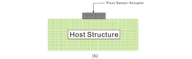
The combined FEM-BEM is applied to compute the actuation effect of a piezo-actuator on a body in this research. Although it seems that FEM is an appropriate method to model the coupling of an actuator and host structure, it is not so effective when the size of the piezodevice and the host structure are very different as shown in Fig. 9 (a) for the two dimensional case. From Fig. 9 (b) it is clearly observed that for such a problem the required elements number becomes so high that does not justify meshing the whole domain and hence using FEM in the first place. Since in reality we are usually dealing with a piezoelectric device, which is much smaller in terms of thickness and surface area compared to the host structure, assuming the host structure as a half-space or a semi-infinite domain seems reasonable for such cases. For numerical analysis of a half-space or any problem having sort of infinity, boundary element method is an excellent tool. However, modeling piezo-device by boundary element method does not seem to be a good idea. Because, as stated, BEM formulations for modeling piezoelectric devices are too complicated and hence FEM is utilized to model the piezoelectric actuator [12].
In Fig. 9 (c) finite element model of piezo-actuator and boundary element model of the host structure are coupled together and the boundary conditions at the interface of the two material is perfectly bonded condition because in practice, the actuator is usually attached on the surface of the structure in a perfect bonded conditions.
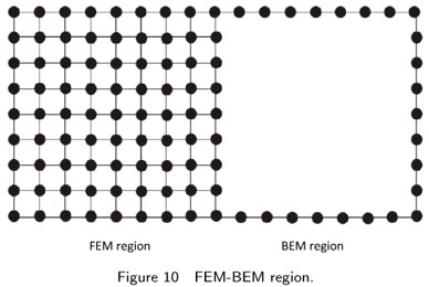
Fig. 10 shows the FEM and BEM regions. In order to combine the two regions together and make the system of equations for the whole system in the finite element approach, the following procedure should be performed. In the boundary element region, before implementing the boundary conditions, the formulation of the system of equations is according to Eq. (22).
In order to consider this region similar to a finite element region, we have to modify Eq. (24) to obtain an equation in the form of a finite element equation. To do so, first we multiply both sides of equation (22) by the inverse of G to obtain:

Next, considering M as a tensor which transforms the vector of nodal tractions of the whole system to that of nodal forces and multiplying both sides of Eq. (24) by M, we obtain the following equation:

or simply

where K' = MG−1H and f is the vector of nodal forces. Eq. (26) is similar to the finite element system of equations and thus boundary element region can be assumed as one super finite element and fed into the existing finite element system of equations. However, it should be noted that K' unlike ordinary finite element stiffness matrices, is not symmetric and after entering the finite element stiffness matrix, it destroys symmetry property of the finite element stiffness matrix.
Calculating M matrix or the traction-to-force transformation matrix accurately is an important step in the finite element coupling approach. The theory is to first consider the following integral [12]:

which, is the boundary tractions weighted by the virtual displacement. For a particular element  is a row vector containing the nodal values of tractions and
  a column vector containing the arbitrary virtual displacements u* . Eq. (27) may now be written as:

Assuming the interpolation functions for u and p as Φ and Ψ, we can write:

Eq. (28) reduces to Eq. (30)

and, the matrix M may then be found from

To make the M transformation tensor numerically, first the traction-to-force transformation matrix (A) is made for each element and then they are all assembled together to form the matrix M which transform all the nodal tractions in the system to nodal forces.
By looking at the Eq. (31) matrix A for an arbitrary element is:

Assembling the M matrix using A matrices of the elements is performed analogously to formation of the stiffness matrix of the system using the element stiffness matrices in finite element method.
7 BOUNDARY CONDITIONS
After the BEM system of equations (26) is fed into the FEM system of equations, boundary conditions should be applied. At the interface of boundary elements (BE) and finite elements (FE) two conditions should be satisfied. First is the equality of the displacements and second is the equilibrium of forces. The first condition is satisfied automatically by assuming that the FE nodes and BE nodes on the interface are coincided and assigning one equation number for those nodes in the FE-BE system of equations. The second one however should be satisfied by considering the equilibrium of forces at the nodes on the interface. After applying interface boundary conditions and also other boundary conditions of a problem the system is ready to be solved similar to FEM problems and the unknown displacement or nodal forces can be obtained.
8 NUMERICAL RESULTS
8.1 A cantilever beam under axial force
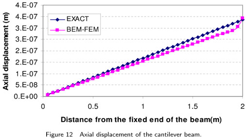
This example is a cantilever beam without piezoelectric properties and with the material elasticity property of, E = 0.2 ×10¹¹ kg/m2 and ν = 0 under the axial load of P = 210 kgf at its end. The length of the beam is 2 m and the dimension of the cross section is 25 ×25 cm2 . The beam has been modeled by a combination of BEM and FEM as in Fig. 11, and the axial displacement obtained along the beam has been plotted in the Fig. 12.
The poisson ratio was assumed as zero because the results are compared with the following exact solution which disregards the effect of Poisson ratio in axial displacement.

where δ is the axial displacement; P is the axial force; l is the distance from the fixed end of the beam; A is the cross sectional area of the beam; and E is the Young modulus.
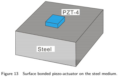
8.2 Surface-bonded PZT-4 actuator on steel half-space
In this example a 6 ×6 ×4mm piezoelectric patch of the transversely isotropic PZT4, working as a piezoelectric actuator is attached on the surface of a steel medium as shown in Fig. 13.
The poling direction of the actuator is along its thickness. A voltage (V) between the upper and the lower electrodes of the actuator is applied which results in an electric field with frequency of f along the poling direction of piezo-actuator. The medium is assumed as a half-space and it has been modeled by 298 boundary elements as in Fig. 14.
The piezo-actuator has been modeled by three and two elements in the plate's length direction and thickness direction respectively and it is placed at the middle of the half space mesh as indicated with green color in Fig. 14. Fig. 15 shows the FEM mesh to model the piezo-actuator using 9 finite elements.
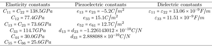
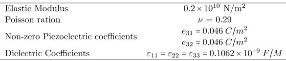
The nonzero elastic, piezoelectric and dielectric constants of PZT4 [50] are:
The host structure on the other hand is made of steel with the Young modulus of E = 0.2 ×10¹¹ kg/m2 and Poisson ratio of ν = 0.29 or the pressure wave velocity of Cp = 5900 m/s and shear wave velocity of Cs = 3200 m/s and density of ρ =7900 kg/m3 . The piezo-actuator is connected to harmonic electric potential of V = 300  exp (5024000it).
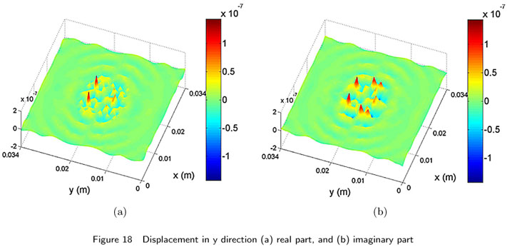
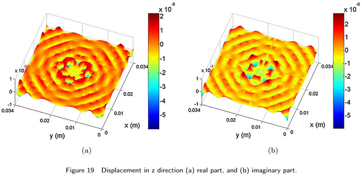
Distribution of the maximum induced displacement field on the surface of the steel medium at x, y and z directions are shown in Fig. 16 and 3-D graphs are shown in Figs. 17, 18, and 19 , respectively. These figures show a high displacement jump at the corners of the actuators especially at x and y directions, which are due to a very high stress concentration especially, shear stress concentration at the corners. The figures also show that for this problem the vertical displacement field is more uniform than the horizontal displacement field, at the vicinities of the actuator or at the interface between the actuator and the steel solid.
Hence from Figs. 16, 17, 18, and 19 , it is clear that the induced displacement by an actuator changes with the change in the thickness of the plate and it is higher for small thickness piezoactuators.
8.3 Surface-bonded PZT-5H actuator on steel (circular half-space)
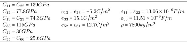
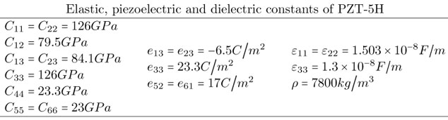
In this example a 6×6×4mm piezoelectric patch of the transversely isotropic PZT-5H, working as a piezoelectric actuator is attached on the surface of a steel medium. The poling direction of the actuator is along its thickness. A voltage (V) between the upper and the lower electrodes of the actuator is applied which results in an electric field with frequency of f along the poling direction of piezo-actuator. The medium is assumed as a circular half-space and it is modeled by 489 boundary elements. The piezo-actuator has been modeled by nine finite elements, three elements in the length direction and one element in the thickness direction. The material properties of the PZT-5H [44] are as follows:
The second medium is made of steel with the Young modulus of E = 0.2 ×10¹² GPa, and Poisson's ratio of ν = 0.29 and density of ρ = 7900 kg/m3 . The piezo-actuator is connected to the time harmonic electric potential of 1 kV and frequency of vibration of 590 kHz. Distribution of induced displacement field in horizontal and vertical directions on the surface of the circular half space steel medium are shown in Fig. 20.
In this example, since the BEM half space is modeled by circular area, the wave propagation is circular. Unlike the previous example, which shows that although the actuator is in rectangular shape but the wave propagation becomes circular when it takes distance from the actuator. Fig. 20 shows high values of displacements on the half space at the corner of actuator.
9 CONCLUSIONS
In this research the coupling of finite element and boundary element for the interaction of a piezoelectric material and an isotropic elastic solid in frequency domain has been performed successfully. The results of this numerical modeling show high jumps in horizontal displacements of the half-space at the corners of the interface between the actuator and the elastic solid medium, which show that the high stress concentration occurs at the corners. In reality this shear stress concentration at the corners of the actuator may cause unwanted debonding between a piezo-actuator and the base structure at the corners and lead to complete debonding of the actuator from the structure.
The results further indicate that the displacement field induced by a piezo-actuator depends on the thickness of the actuator and for the thicker actuator we have smaller values of displacement induced in the host structure.
The numerical simulation of the actuation behavior of a piezo-actuator on another structure has high applications in actuator designing. It can help the actuator designer to find the appropriate dimensions and choose the material properties by numerically analyzing different existing options instead of performing more costly experiments for every case.
The presented work will serve as a useful step towards modeling of structural health monitoring systems. By using the suggested BEM-FEM coupled model for actuators with different dimensions or material properties much useful information on the effect of each of these parameters on the amount of actuation and load transfer can be obtained.
FUTURE WORKS
In future research in the following directions should be performed:
1. Time domain analysis of the coupling of a piezoelectric material and an elastic solid.
2. Comparison of the actuation effects of a surface bonded actuator and an embedded actuator.
3. Study the interaction of two or more actuators bonded on the surface of a structure.
4. Modeling a piezo-sensor and study its coupling with a structure.
Acknowledgements The author thankfully acknowledges the support provided by the Specialty Units for Safety and Preservation of Structures, College of Engineering, King Saud University, Riyadh, Saudi Arabia for conducting this research.
Received 12 Jan 2011;
In revised form 12 May 2011
- [1] Structures technology for future aerospace systems. In A.K. Noor, editor, Progress in Astronautics and Aeronautics, volume 188. American Institute of Aeronautics and Astronautics, 2000.
- [2] O. J. Aldraihem, T. Singh, and R.C. Wetherhold. Optimal size and location of piezoelectric actuator/sensors: practical considerations. J. Guid. Control Dynam., 23(3):509515, 2000.
- [3] R. Ali, D. R. Mahapatra, and S. Gopalakrishnan. An analytical model of constrained piezoelectric thin film sensors. Sensors Actuators A, 116:424437, 2004.
- [4] R. Ali, D. R. Mahapatra, and S. Gopalakrishnan. Constrained piezoelectric thin film for sensing of subsurface cracks. Smart Mater. Struct., 14:376386, 2005.
- [5] H. Allik and T. J. R. Hughes. Finite element method for piezoelectric vibrations. International Journal for Numerical Methods in Engineering, 2:151157, 1970.
- [6] APC International Ltd., PA, USA. Piezoelectric Ceramics: Principles and Applications, 2002.
- [7] K. J. Bathe. Finite element procedures Prentice-Hall, Englewood Cliffs, N.J., 1996.
- [8] M. P. Bendsøe. and O. Sigmund. Topology Optimization Theory, Methods and Applications Springer, Berlin, Heidelberg, New York, 2003.
- [9] A. Benjeddo. Advances in piezoelectric finite element modeling of adaptive structural elements: a survey. Computers and Structures, 76:347363, 2000.
- [10] A. Benjeddou. Advances in piezoelectric finite element modeling of adaptive structural elements: a survey. Comput. & Struct., 76:347363, 2000.
- [11] C. A. Brebbia. Boundary elements. In XVIII Proceedings of the 28th International Conference on Boundary Element and other Mesh Reduction Methods, Southampton and Boston, 2006. WIT Press.
- [12] C. A. Brebbia and P. Georgiou. Combination of boundary and finite elements in elastostatics. Applied Mathematical Modeling, 3:212220, 1979.
- [13] C. A. Brebbia, J. C. Telles, and L. C. Wrobel. Boundary element techniques. Springer Verlag, Berlin and New York, 1984.
- [14] R. C. Carbonari, E. C. N. Silva, and S. Nishiwaki. Design of piezoelectric multi-actuated micro-tools using topology optimization. Smart Mater. Struct., 14:14311447, 2005.
- [15] Z. Chaudhry and C. A. Rogers. The pin-force model revisited. Journal of Intelligent Material Systems and Structures, 5:34754, 1994.
- [16] I. Chopra. Review of state of art of smart structures and integrated systems. Am. Inst. Aeronaut. Astronaut. J., 40(11):21452187, 2002.
- [17] R. D. Cook, D. S. Malkus, M. E. Plesha, and R. J. Witt. Concepts and applications of finite element analysis John Wiley and Sons, Inc., N.Y., 4th edition, 2002.
- [18] E. F. Crawley and E. H. Anderson. Detailed models of piezoceramic actuator beams. Journal of Intelligent Material Systems and Structures, 1:425, 1990.
- [19] E. F. Crawley and J. D. Luis. Use of piezoelectric actuators as elements of intelligent structures. AIAA Journal, 25:13731385, 1987.
- [20] M. Denda and J. Lua. Development of the boundary element method for 2D piezoelectricity. Compos. Part B, 30:699707, 1999.
- [21] Q. L. Deng and Z. Q. Wang. Analysis of piezoelectric materials with an elliptical hole. Acta Mech. Sinica, 34(1):109 114, 2002.
- [22] A. Donoso and O. Sigmund. Optimization of piezoelectric bimorph actuators with active damping for static and dynamic loads. Struct. Multidiscip. Optim., 38(2):171183, 2008.
- [23] J. Eberhardsteiner, H. A. Mang, and P. Torzicky. Three dimensional elasto-plastic BE-FE stress analysis of the excavation of a tunnel bifurcation on the basis of a substructuring technique. In Advances in Boundary Element Techniques, pages 103128, Berlin, 1993. Springer.
- [24] M.I. Frecker. Recent advances in optimization of smart structures and actuators. J. Intell. Mater. Syst. Struct., 14:207216, 2003.
- [25] U. Gabbert and C.-T. Weber. Optimization of piezoelectric material distribution in smart structures. In Proceedings of SPIE-The International Society for Optical Engineering, volume 3667, pages 1322, 1999.
- [26] F. Gao, Y. Shen, and L. Li. Optimal design of piezoelectric actuators for plate vibro acoustic control using genetic algorithms with immune diversity. Smart Mater. Struct., 9:485491, 2000.
- [27] N. Guo, P. Cawley, and D. Hitching. The finite elements analysis of the vibration characteristics of piezoelectric discs. Journal of sound and vibration, 159(1):115138, 1992.
- [28] D.E. Herverly II, K.W. Wang, and E.C. Smith. An optimal actuator placement methodology for active control of helicopter airframe vibrations. J. Am. Helicopter Soc., 46:251261, 2001.
- [29] K. Hiramoto, H. Doki, and G. Obinata. Optimal sensor/actuator placement for active vibration control using explicit solution of algebraic Riccati equation. J. Sound Vib., 229(5):10571075, 2000.
- [30] G.L. Huang and C.T. Sun. The dynamic behavior of a piezoelectric actuator bonded to an anisotropic elastic medium. Int. J. Solids Struct., 43:12911307, 2006.
- [31] T. Ikeda. Fundamentals of Piezoelectricity Oxford University Press, Inc., N.Y., 1996.
- [32] S. Im and S. N. Atluri. Effects of a piezo-actuator on a finite deformation beam subjected to general loading. AIAA Journal, 27:18011807, 1989.
- [33] R. A. Jeans and I. C. Matthews. Solution of fluid-structure interaction problems using a coupled finite element and variational boundary element technique. Journal of the Acoustical Society of America, 88:24592466, 1999.
- [34] C. D. Junior, A. Erturk, and D. J. Inman. An electromechanical finite element model for piezoelectric energy harvester plates. Journal of Sound and Vibration, 327:925, 2009.
- [35] J. Juuti, K. Kord, R. Lonnakko, V.-P. Moilanen, and S. Leppävuori. Mechanically amplified large displacement piezoelectric actuators. Sensors and Actuators A, 120:225231, 2005.
- [36] J. E. Kim, D. S. Kim, P. S. Ma, and Y. Y. Kim. Multi-physics interpolation for the topology optimization of piezoelectric systems. Comput. Methods Appl. Mech. Engrg., 199:31533168, 2010.
- [37] M. Kogl and L. Gaul. A boundary element method for transient piezoelectric analysis. Engrg. Anal. Boundary Elements, 24:591598, 2000.
- [38] M. Kögl and E. C. N. Silva. Topology optimization of smart structures: design of piezoelectric plate and shell actuators. Smart Mater. Struct., 14:387399, 2005.
- [39] G. Kulkarni and S. V. Hanagud. Modeling issues in the vibration control with piezoelectric actuators. Smart Structure and Material, 24:717, 1991.
- [40] C. M. LaPeter and H. H. Cudney. Design methodology for piezoelectric actuators. Smart Structures and Material, 24:139143, 1991.
- [41] X. Li, J.S. Vartuli, D.L. Milius, I.A. Aksay, W.Y. Shih, and W.-H. Shih. Electromechanical properties of a ceramic d31-gradient flextensional actuator. J. Am. Ceram. Soc., 84:9961003, 2001.
- [42] M. W. Lin and C. A. Rogers. Modeling of the actuation mechanism in a abeam structure with induced strain structures. In Proceedings of AIAA/ASCE/ASME/AHS/ASC 34th Structures, Structural Dynamics, and Materials Conference, volume 6, pages 36083617, Washington DC, La Jolla, CA., 1993. AIAA Inc.
- [43] S. I. E. Lin. The theoretical and experimental studies of a circular multi-layered annular piezoelectric actuator. Sensors and Actuators A: Physical, 165:280287, 2011.
- [44] W. Liu, B. Jiang, and W. Zhu. Self-biased dielectric bolometer from epitaxially grown Pb(Zr,Ti)O3 and lanthanum-doped Pb(Zr,Ti)O3 multilayered thin films. Applied Physics Letters, 77(7):10471049, 2000.
- [45] P. Lu and O. Maharenholtz. A variational boundary element formulation for piezoelectricity. Mech. Res. Commun., 21:605611, 1994.
- [46] J. Mackerle. Sensors and actuators: finite element and boundary element analyses and simulations. A bibliography (19971998), Finite Elements Anal. Des., 33:209220, 1999.
- [47] J. Main, E. Garcia, and D. Howard. Optimal placement and sizing of paried piezoactuators in beams and plates. Smart Material and Structure, 3:373381, 1994.
- [48] M. Naillon, R. Coursant, and F. Besnier. Analysis of piezoelectric structures by a finite element method. Acta Electronica, 25:341362, 1983.
- [49] S. Nishiwaki, M. Frecker, S. Min, and N. Kikuchi. Topology optimization of compliant mechanisms using homogenization method. International Journal for Numerical Methods in Engineering, 42:535559, 1998.
- [50] J. Rouquette, J. Haines, V. Bornand, M. Pintard, Ph. Papet, C. Bousquet, L. Konczewicz, F. A. Gorelli, and S. Hull. Pressure tuning of the morphotropic phase boundary in piezoelectric lead zirconate titanate. Phys. Rev. B, 70(1):014108, 2004.
- [51] C. E. Seeley and A. Chattopadhyay. Modeling of adaptive composites including debonding. International Journal of Solids and Structures, 36(12):18231843, 1999.
- [52] D. K. Shah, S. P. Joshi, and W. S. Chan. Static structural response of plates within piezoceramic layers. Smart Materials and Structures, 2:17280, 1993.
- [53] W.C. Staszewski, C. Boller, and G.R. Tomlison, editors. Health Monitoring of Aerospace Structures Smart Sensor Technologies and Signal Processing John Wiley & Sons Ltd., 2004.
- [54] G. Strambi, R. Barboni, and P. Guandenzi. Pin-force and Euler-Bernoulli mode1 for analysis of intelligent structures. AIAA Journal, 3:17461749, 1994.
- [55] A. Suleman and M.A. Gonclaves. Multi-objective optimization of an adaptive composite beam using the physical programming approach. J. Intell. Mater. Syst. Struct., 10:5670, 2000.
- [56] K. Y. Sze, H. T. Wang, and H. Fan. A finite element approach for computing edge singularities in piezoelectric materials. Int. J. Solids Struct., 38:92339252, 2001.
- [57] H. F. Tiersten, editor. Linear piezoelectric plate vibrations Plenum, New York, 1969.
- [58] H. F. Tiersten. Surface waves guided by thin films. Journal of Applied Physics, 40:770789, 1969.
- [59] H. S. TZOU. Piezoelectric shells (distributed sensing and control of continua Kluwer Academic Publishers, Boston/Dordrecht, 1993.
- [60] B. T. Wang and C. A. Rogers. Laminate plate theory for spatially distributed strain actuators. Journal of Composite Material, 25:433452, 1991.
- [61] J. Yang. An introduction to the theory of piezoelectricity Springer Science + Business Media, Inc., Boston, 2005.
- [62] C.-B. Yoon, S.-H. Lee, S.-B. Seo, and H.-E. Kim. PZN-PZT flextensional actuators with conducting PZN-PZT/Ag layer by co-firing method. J. Am. Ceram. Soc., 87(9):16631668, 2004.
- [63] C.-B. Yoon, S.-M. Lee, S.-H. Lee, and H.-E. Kim. PZN-PZT flextensional actuator by co-extrusion process. Sensors and Actuators A, 119:221227, 2005.
- [64] G.H. Yoon and O. Sigmund. A monolithic approach for topology optimization of electrostatically actuated devices. Comput. Meth. Appl. Mech. Engrg., 197:40624075, 2008.
- [65] H. Zhang, B. Lennox, P.R. Goulding, and A.Y.T. Leung. Float-encoded genetic algorithm technique for integrated optimization of piezoelectric actuator and sensor placement and feedback gains. Smart Mater. Struct., 9:552557, 2000.
- [66] J. Zhang, B. Zhang, and J. Fan. A coupled electromechanical analysis of piezoelectric layer bonded to an elastic substrate: Part I. Development of governing equations. Int. J. Solids Struct., 40:67816797, 2003.
- [67] Z. H. Zhao, Y. P. Wang, X. D. Zhao, and Yi Kun Yuan. A new electromechanical coupling model for piezoelectric actuator. Advanced Materials Research, 97-101:867870, 2010.
- [68] O. C. Zienkiewicz, D. W. Kelly, and P. Bettes. The coupling of the finite element method and boundary solution procedures. International Journal for Numerical Methods in Engineering, 11:35575, 1977.
Publication Dates
-
Publication in this collection
19 Dec 2011 -
Date of issue
Sept 2011
History
-
Received
12 Jan 2011 -
Accepted
12 Mar 2011