Abstract
We study the milling process of Inconel. By continuously increasing the cutting depth we follow the system response and appearance of oscillations of larger amplitude. The cutting force amplitude and frequency analysis has been done by means of wavelets and Hilbert-Huang transform. We report that in our system the force oscillations are closely related to the rotational motion of the tool and advocate for a regenerative mechanism of chatter vibrations. To identify vibrations amplitudes occurrence in time scale we apply wavelet and Hilbert-Huang transforms.
milling; wavelet analysis; Hilbert-Huang transform; nonlinear vibration
Cutting force response in milling of Inconel: Analysis by wavelet and Hilbert-Huang Transforms
Grzegorz Litak* * Author email: g.litak@pollub.pl ; Krzysztof Kecik; Rafal Rusinek
Faculty of Mechanical Engineering, Lublin University of Technology, PL-20-618 Lublin, Poland
ABSTRACT
We study the milling process of Inconel. By continuously increasing the cutting depth we follow the system response and appearance of oscillations of larger amplitude. The cutting force amplitude and frequency analysis has been done by means of wavelets and Hilbert-Huang transform. We report that in our system the force oscillations are closely related to the rotational motion of the tool and advocate for a regenerative mechanism of chatter vibrations. To identify vibrations amplitudes occurrence in time scale we apply wavelet and Hilbert-Huang transforms.
Keywords: milling, wavelet analysis, Hilbert-Huang transform, nonlinear vibration
1 INTRODUCTION
The modern massive production cannot most often exist without the machining technology. The problems of dynamical instabilities of cutting process and associated harmful chatter vibrations were known for many years.
The recent development of cutting and milling concepts and techniques gave way to improve the process stability in fairly high speed cutting [1]. Consequently, identification of the chatter oscillations, and their elimination or even stabilization on some low level have become a high interest in science and technology [2-7]. Altintas [2] presented vibration and experimental modal analysis of the machine-tool system in a cutting process. A special focus was placed on chatter vibration generation by the regenerative effect. Additionally, the selection of drive actuators, feedback sensors, the design of real time trajectory generation and interpolation algorithms were discussed. Warminski et al [3] considered a model of the metal cutting process in the context of an approximate analysis of the resulting non-linear differential equations of motion. The technological parameters for the avoidance of primary chatter were presented. Insperger and Mann [4] analyzed the stability conditions for up- and down-milling operations using the semi-discretization method. The authors restricted their study to a single degree-of-freedom milling model with a linear cutting force and a single cutting tooth. The method of temporal finite elements was applied in the paper [5]. The periodic chatter-free motion of the tool and the corresponding surface location error (SLE) were obtained by solving the differential equations. It was shown that the SLE was large at the spindle speeds where the ratio of the dominant frequency of the tool and the tooth passing frequency was an integer [6]. The stability lobe diagrams and the corresponding frequency diagrams are compared for milling models with and without runout [7]. The plausible adaptive control concept, based on relatively short time series, has been studied to gain deeper understanding of cutting and milling processes [8, 9].
Recently, new materials have been widely tested in various applications including aircraft parts due to their high specific strength and stiffness, low density and corrosion resistance. Inconel was one of the materials due to its high strength over a wide temperature range. It also forms a thick, stable, passivating oxide layer protecting from corrosion.
The disadvantage of Inconel is the difficulty of using traditional machining techniques due to rapid work hardening. After the first pass of the tool in cutting or milling, work hardening can plastic deform the workpiece on subsequent passes. Therefore Inconel is considered as a material of hard machinability [10, 11, 12], and consequently, minimizing the number of tool passes is suggested.
2 EXPERIMENTAL PROCEDURE AND MEASUREMENTS
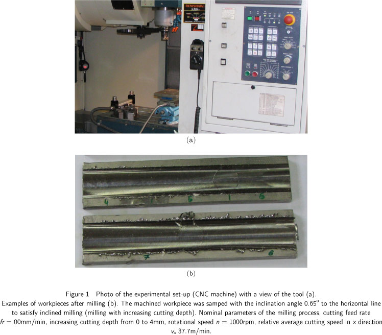
The measurements were carried out on a vertical machining centre FV580A with the Fanuc 0iMC control system (Fig. 1). Forces were measured using a Kistler 9257B dynamometer and a 5017B charge amplifier and the sample and hold component (SC2040) and the analog-digital converter NI6071E (National Instrument). The SC-2040 module is an eight-channel simultaneously sampling differential amplifier produced by National Instrument Company. Microprocessor-controlled Multichannel Charge Amplifier type 5017B is especially used for combined force and moment measurements together with piezoelectric multicomponent dynamometers.
The cutting forces generated on the workpiece during the machining are measured by dynamometer mounted on the milling machine. The corresponding force signals are trans mitted to charge amplifier next to module sample & hold and finally to analog-digital converter, which is connected to a computer system. The sampling rate of data reordered during the test was fixed to 5kHz. The material used in the experiment is Inconel 718 (nickel superalloy). In the experiment, the solid carbide end mill no. F4BT1200AWX45R100 (Kennametal) with a diameter of 12mm and 4 cutting blades is used during machining. The radial depth of cut is two thirds of end milling diameter (8mm).
3 WAVELET AND HILBERT-HUANG ANALYSES
Wavelets have been used for time series analysis in a wide variety of applications. Wavelet analysis provides a spectral-temporal approach to identify the dominant modes of variability in a time series and to delineate how these modes vary over time [8, 9, 13] The continuous wavelet transform (CWT) of the time series Fx(n) with respect to a mother wavelet ψ(t) is given by the convolution of the time series with a scaled and translated version of ψ(t). The convolution is expressed by [14]:

where < Fx >, σFx denote the mean value and standard deviation of the cutting force component Fx , δt denotes the sampling interval, while an asterisk on ψ the complex conjugate. In Eq. (1) n and n′ ϵ [1,N] enumerate the sampled values of force Fx. Furthermore, in W(s, n), the symbols s and n are scale and time indices, controlling the dilatation or contraction and indicating the location of time instant in the examined time series. Morlet wavelet consists of a plane wave modulated by a Gaussian function and is described by [14]

where the nondimensional frequency ω0 = 2f0 defines the order of the wavelet, with f0 being the center frequency, i is an imaginary unit, and the argument η defines dimensionless time (as in Eq. (1)). The value of ω0 controls the number of oscillations that is present in the mother wavelet and thus influences the frequency and time resolutions of the corresponding wavelet transform. A larger value of ω0 provides a higher frequency resolution whereas a smaller value improves the time resolution. In our computations, we have used a Morlet wavelet of order ω0= 6 as the mother wavelet. This choice provides a good balance between time and frequency localizations.
The wavelet power spectrum (WPS)

is a measure of the variance at different scales or frequencies. The WPS which depends on both scales, frequency and time, can be applied to non-stationary time series (Fig. 2). The results of CWT are presented in Fig. 3. Pw changes with changing time and period (inverse frequency f-1) is represented by a corresponding color (or shade of gray). It is worth mentioning, that Pw reaches maximum values for spindle frequency of f=1/0.06 Hz=1000 rpm. Other maxima are visible at 3f = 1/0.02 and 4f = 1/0.015 Hz, and less spectacular at 2f = 1/0.03 Hz. These higher harmonics are not so much important in the beginning for t < 15 s but their contribution is growing with increasing cutting time (and simultaneously the cutting depth).
The clear appearance of all higher harmonics after the time instant t ≈ 15s indicates that all four milling blades are synchronized with quarter period oscillations. Such a synchronization could be an effect of nonlinearities and could reflect the regenerative effect. The previous pass with the same cutting velocity is causing the surface corrugation which effects the present tool pass.
In the analysis by Hilbert-Huang one performs the so-called signal decomposition into experimental modes (Huang decomposition): Fx1(t), Fx2(t), ..., Fxm(t) [15]:

where rm is a truncation error. Each next experimental j mode is defined after subtracting average of maximum and minimum values interpolated by a cubic splines of the local envelope Fxj-1 (t) . Note that the first mode Fx1(t) is obtained from the original signal Fx(t) = Fx0(t) and the Huang decomposition procedure.
The first 6 modes obtained using the above schema are plotted in Fig. 4. Note that modes 1-4 are not changing so much with increasing time but mode 5 and 6 are growing rapidly with time after passing the characteristic t ≈ 16s.
Each of individual mode has different amplitude-frequency dependence. To examine this effect with more carefully one usually performs the Hilbert transform H(.) on individual modes [16, 17, 18, 19]. Finally, the Hilbert transform is defined as the convolution of the time series Fxj(t) and the function 1/t. For discrete time, integer sampling values n (or time instants tn, where tn = nδt) [16] this convolution reads

The results of amplitude-frequency dependence for initial and final intervals of cutting (Fig. 1) are presented in Fig. 5a-f, for 1-6 modes, respectively. One can easily see the clear decreasing of resonant frequency for higher cutting depth (visible in all plots apart from Fig. 5c). First modes possess a lot of noise which is visible in the broad distribution of points on the plots Fig. 5a-b. In contrast, to the lower cutting depth the distribution of frequencies are more narrow which could indicate that amplitude is less dependent on frequency, presumably due to the strong synchronization effect. This tendency of frequency shrinking is much smaller but is also visible in Fig. 5a-b.
4 CONCLUSIONS
The results of measurement and analysis of signals are based on the wavelet and Hilbert-Huang transforms. This methods, unlike the Fourier transform, can be applied to the nonstationary signals, in our case, the milling process is performed with the linearly increasing depth cut. Wavelet power spectrum show the appearance of higher harmonics which could be caused by the combined effect of the typical structural and frictional nonlinearities and regenerative effect.
Hilbert transform shows some additional features of larger amplitude chatter vibrations. The response of the system with higher cutting depth is not only more pronounced but also more regular. This could be due to the specific plastic deformations which the surface is exposed on after each tool pass. Note that the larger cutting depth can minimize this effect [12].
In contrast to previous experimental studies [4], where the stability of the milling process where investigated for a series of different depths h, we performed the inclined milling with continuously increasing cutting depth. Such a procedure enabled us to monitor the stability of milling in the real time and to find the critical cutting depth beyond which the milling process becomes unstable. In our case it was about h≈0.3 mm which corresponds to t≈16 s (see modes 5 and 6 in Fig. 4).
On the other hand, we claim that the Huang decomposition can be also very useful method to identify the chatter vibrations itself. It could be used to study the nonstationary signal like our force response to the increasing cutting depth. This is observed in Fig. 4 where the modes 5 and 6 are signaling the appearance of harmful chatter vibrations in the technological process of milling. This multiresolution analysis can be combined with other statistical and/or symbolic methods to define the efficient indicators of chatter appearance. All calculations and graphs were made by using MATLAB.
Acknowledgements This research has been partially supported by European Union within the framework Integrated Regional Development Operational Programme as the project POIG.0101.02-00-015/08.
Received 21 Mar 2012
In revised form 29 May 2012
- [1] G. Quintana, J. Ciurana, Chatter in Machining processes: A review, Int. J. Mach. Tools Manuf. 51, 363 - 376 (2011).
- [2] Y. Altintas, Manufacturing Automation: Metal Cutting Mechanics, Machine Tool Vibrations, and CNC Design, Cambridge University Press, Cambridge 2000.
- [3] J. Warminski, G. Litak, M.P. Cartmell, R. Khanin, and M. Wiercigroch, Approximate analytical solutions for primary chatter in the nonlinear metal cutting model,J. Sound Vibr. 259, 917 - 933 (2003).
- [4] B.P. Mann, T. Insperger, P.V. Bayly, G. Stepan, Stability of up-milling and down-milling, part 2: experimental verification, Int. J. Mach. Tools Manuf. 43, 35 - 40 (2003).
- [5] B.P. Mann, P.V. Bayly, M.A. Davies, J.E. Halley, Limit cycles, bifurcations, and accuracy of the milling process, J. Sound Vibr. 277, 31 - 48 (2004).
- [6] T. Insperger, J. Gradisek, M. Kalveram, G. Stepan, K. Winert, and E. Govekar, Machine tool chatter and surface location error in milling processes, Journal of Manufacturing Science and Engineering 128, 913 - 920 (2006).
- [7] T. Insperger, B.P. Mann, T. Surmann, G. Stepan, On the chatter frequencies of milling processes with runout, Int. J. Mach. Tools Manuf. 48, 1081 - 1089 (2008).
- [8] A.K. Sen, G. Litak, A. Syta, Cutting process dynamics by nonlinear time series and wavelet analysis, Chaos 17, 023133 (2007).
- [9] A.K. Sen, G. Litak, A. Syta, R. Rusinek, Complex dynamics in milling of fiber-reinforced composites, Meccanica 2012, submitted.
- [10] H.Z. Li, H. Zeng, X.Q. Chen, An experimental study of tool wear and cutting force variation in the end milling of Inconel 718 with coated carbide inserts, Journal of Materials Processing Technology 180, 296 - 304 (2006).
- [11] A. Devillez, F. Schneider, S. Dominiak, D. Dudzinski, D. Larrouquere, Cutting forces and wear in dry machining of Inconel 718 with coated carbide tools, Wear 262, 931 - 942 (2007).
- [12] K. Kecik, R. Rusinek, J. Warminski, Stability lobes analysis of nickel superalloys milling, Int. J. Bif. Chaos 21, 1 - 12 (2011).
- [13] P. Kumar, E. Foufoula-Georgiou, Wavelet analysis for geophysical applications, Rev. Geophys. 35, 385 - 412 (1997).
- [14] C. Torrence, G.P. Compo, A practical guide to wavelet analysis, Bull. Amer. Meteorol. Soc. 79, 61 - 78 (1998)
- [15] N.E. Huang, Z. Shen, S.R. Long, M.L.C. Wu, H.H. Shih, Q.N. Zheng, N.C. Yen, C.C. Tung, H.H. Liu, The empirical mode decomposition and the Hilbert spectrum for nonlinear and non-stationary time series analysis, Proc. Roy. Soc. Lond. 454, 903 - 993 (1998).
- [16] D. Hilbert, Grundzuege einer allgemeinen Theorie der linearen Integralgleichungen, Chelsea Pub. Co., New York 1953 (282 pages).
- [17] M. Feldman, Hilbert transform in vibration analysis, Mech. Sys. Sig. Process. 25, 735-802 (2011).
- [18] P. Lajmert, An application of Hilbert-Huang transform and principal component analysis for diagnostics of cylindrical plunge grinding process, Journal of Machine Engineering 10, 39 - 49 (2010).
- [19] P. Lajmret, B. Kruszczynski, A diagnostic system for cylindrical plunge grinding process based on Hilbert-Huang transform and principal component analysis. Adv. Manuf. Sci. Technol. 34, 19 - 31 (2010).
Publication Dates
-
Publication in this collection
25 Feb 2013 -
Date of issue
Jan 2013
History
-
Received
21 Mar 2012 -
Accepted
29 May 2012