
Abstract
In this paper closed form analytical solution for stress components of thick spherical shell made of transversely isotropic functionally graded hyperelastic material subjected to internal and external pressure is presented. Reinforced neo-Hookean strain energy function with variable material parameters is used to model pressure vessel material. The material constants of strain energy function are graded along the radial direction based on a power law function and have been calculated from experimental data by using Levenberg-Marquardt nonlinear regression method. Stress components and stretches of pressure vessel have been obtained for centrally symmetric condition. Following this, profiles of extension ratio, deformed radius of sphere, normalized radial stress and normalized circumferential stress are plotted as a function of radius of sphere in the undeformed configuration for different material inhomogeneity parameter (m). The obtained results show that the inhomogeneity properties of FGMs structure parameter  have a significant influence on the displacement, stretch and stresses distribution along the radial direction.
Keywords:
Transversely isotropic hyperelastic material; thick-walled spherical shells; finite deformation; functionally graded material
1 INTRODUCTION
The principal problem in the elasticity theory is to find the relation between the stress and the strain in a body under certain external forces. In small deformation, linear elasticity and Hooke's law are applied to find stress-strain relation but in large deformation, materials show nonlinear elastic behavior which can be characterized by hyperelasticity. Examples of these nonlinear elastic materials are rubber like materials and soft tissues. Constitutive models for rubber like materials and soft tissues are often considered with incompressibility assumption. Because of the geometric simplification of zero volume change, from the mathematical point of view the advantage of the incompressibility assumption is simplifying the nonlinear equations to describe the mechanical behavior of hyperelastic materials. Thus it has been possible to get analytical closed-form solutions for a wide group of interesting problems in this case. Simple constitutive relations for studying their mechanical behavior consist of the neo-Hookean and the Mooney-Rivlin strain energy functions. Modeling the mechanical behavior of rubber like materials within the framework of nonlinear elasticity theory was the subject of a lot of studies, which could be found in the review articles contributed by Beatty (1987)Beatty,M.F., (1987) Topics in finite elasticity: hyperelasticity of rubber, elastomers, and biological tissues-with examples. Applied Mechanics Review 40(12): 1699-1735., Horgan and Polignone (1995)Horgan,C.O. and Polignone,D.A. (1998), Cavitation in nonlinearly elastic solids: A review. Applied Mechanics Review 48(8): 471-485., Attard (2003)Attard,M.M. (2003), Finite strain-isotropic hyperelasticity. International Journal of Solids and Structures 40(17): 4353-4378. and the monograph contributed by Fu and Ogden(2001)Fu,Y.B. and Ogden,R.W.,(2001) Nonlinear Elasticity. Cambridge University Press.. In the recent years numerous investigations were done on constitutive modeling of hyperelatic materials under different loading condition such as works by Anani and Alizadeh (2011)Anani, Y. and Alizadeh, Y., (2011), Visco-hyperelastic constitutive law for modeling of foam's behavior, J of Material & Design 32(5):2940-2948.,Bao et al. (2003)Bao R.H., Xue P., Yu T.X., Tao X.M. TAO (2003) Numerical simulation of large deformation of flat-topped conical shells made of textile, Latin American Journal of Solid and Structures 1:25-47. Pascon and Coda (2013)Pascon J.P. and Coda H.B., (2013), Large deformation analysis of homogeneous rubber-like materials via shell finite elements, Latin American Journal of Solid and Structures 10:1177-1210.. As a result of continually increasing uses of rubber like materials and soft tissues, researchers have attracted to study and analyze the behavior of these materials, related boundary value problems and composed structures of them. Analyzing thick pressure vessel is one of the most popular and interesting boundary value problems in the mechanical engineering. Shells are general structural elements in many engineering applications, including pressure vessels, sub-marine hulls, ship hulls, wings and fuselages of airplanes, automobile tires pipes, exteriors of rockets, missiles, concrete roofs, chimneys, cooling towers, liquid storage tanks, and many other structures. Furthermore they are found in nature in the form of leaves, eggs, inner ear, bladder, blood vessel, skulls, and geological formations (Reddy 2007Reddy, J.N.(2007), Theory and Analysis of Elastic Plates and Shells, Boca Raton: CRC Press, 403p.), therefore, the main concern of this paper is transversely isotropic thick spherical shell made of Functionally Graded (FG) rubber like materials. Rapid growth in technology has ushered in an era when it is possible to synthesize materials that exhibit a variation/graded-variation in their properties for proper design in different components such as shells and pressure vessels. A Functionally Graded Material (FGM) is nonhomogeneous in composition. The properties of these materials may change gradually and continuously along the coordinate. These variable properties can be simulated using an analytical function. This functional distribution of material properties can help researchers in order to control the distribution of displacement or stress in a solid structure. There is extensive literature on FGMs pressure vessels in linear elasticity and it is impossible to review it in a paper other than in a review article but some recent researches are done by Nie et al. (2011)Nie, G., Zhong, Z., Batra, R., (2011), Material tailoring for functionally graded hollow cylinders and spheres, Comp. Sci. Tech. 71:666-673.,Ghannad and Nejad (2012)Ghannad, M. and Nejad, M. Z., (2012), Complete closed-form solution for pressurized heterogeneous thick spherical shells, Mechanika, 18(5):508-516., Gharooni and Ghannad (2015)Gharooni H., Ghannad M., (2015), Elastic analysis of pressurized thick fgm cylinders with exponential variation of material properties using tsdt, Latin American Journal of Solid and Structures 12: 1024-1041. and Ghasemi et al (2015)Ghasemi, F.A., Malekzadeh fard, K., Azarnia, A., (2015), High order impact elastic analysis of circular thick cylindrical sandwich panels subjected to multi-mass impacts, Latin American Journal of Solid and Structures 12: In press..
In spite of numerous works on FGMs in linear elasticity, there is hardly any research related to functionally graded rubber like materials. For the first time, graded rubber like materials were created by Ikeda (1998)Ikeda, Y, Kasai, Y., Murakami, S., Kohjiya, S., (1998), Preparation and mechanical properties of graded styrene-butadiene rubber vulcanizates, J. Jpn. Inst. Metals, 62: 1013-1017. via a construction-based method in the laboratory. Inhomogeneities can be introduced in rubber like materials either during vulcanization or uneven interaction with thermal, radiative and oxidative environments (Bilgili 2002Bilgili, E., Bernstein, B., Arastoopour, H., (2002), Influence of material non-homogeneity on the shearing response of a neo-Hookean slab. Rubber Chem Technol. 75(2):347-363.). Bilgili et al. also treated the material nonhomogeneity within the context of hyperelasticity and finite thermoelasticity (2003Bilgili, E., (2003), Controlling the stress-strain inhomogeneities in axially sheared and radially heated hollow rubber tubes via functional grading, Mech. Res. Commun. 30:257-66.). Their studies confirmed that the spatial variation pattern of the nonhomogeneity has a great influence on the stress-strain fields and that strong localization in the form of boundary layers can occur. Moreover, Bilgili worked to clarify effects of material inhomogeneities on through-the-thickness stress distributions and how to employ them for optimally designing circular cylinders made of rubber like materials. In another study plane strain deformations of a circular cylinder made of an inhomogeneous neo-Hookean material with circumferential displacements prescribed on the inner and the outer surfaces studied by Bilgili (2004)Bilgili, E., (2004), Modelling mechanical behaviour of continuously graded vulcanized rubbers., Plast Rubbers Compos 33(4):163-169..Batra (2006)Batra, R.C., (2006), Torsion of a functionally graded cylinder. AIAA J, 44:1363-1365. analyzed the torsion of a cylinder made of incompressible Hookean material with the shear modulus varying along the axial direction, and found the axial variation of the shear modulus to manage the angle of twist of a cross-section. Batra and Bahrami (2003)Batra, R.C. and Bahrami, A., (2003) Inflation and eversion of functionally graded nonlinear elastic incompressible cylinders, Int. J. of Non-Linear Mechanics, 44: 311-323. investigated cylindrical pressure vessel made of FG rubber like material under internal pressure. To calculate stress components of the pressure vessel, they assumed axisymmetric radial deformations of a circular cylinder composed of FG Mooney-Rivlin material with the material parameters varying continuously through the radial direction either by a power law or an affine relation.
Surveying through the researches done on different structures gives a clear view of a gap in analyzing spherical shell made of transversely isotropic FG rubber like materials although such spherical shells gain attentions in engineering applications. Therefore, stress analyzing of above mentioned spheres is the objective of this research. To that end, exact analytical solution is derived for stresses and displacements of pressurized thick spheres made of transversely isotropic functionally graded rubber like materials (FGM) with power law variation material properties in radial direction.
2 PROBLEM FORMULATION
A hollow thick sphere with an inner radius A and an outer radius B made of transversely isotropic FG rubber like materials is considered. The sphere is subjected to internal and external pressure pi and porespectively (Fig. 1) and also it is assumed to be an initially stress-free thick-walled sphereand deformed statically. We consider (R, Θ, Φ) and (r, ϑ, φ) are the spherical coordinates in the undeformed and deformed configurations, respectively. In these configurations the geometry of the sphere are described as follows:


With the assumption of centrally symmetric deformation, the deformation of spherical shell is given by:

The above deformation field is a member of the family of universal solutions proposed by Ericksen (1954)Ericksen, J.L., (1954), Deformations possible in every isotropic incompressible perfectly elastic body, Z. Angew. Math. Phys. 5:466-486.. The deformation gradient F is given by:

Where,  . In this problem, R = I, therefore, V = F. The corresponding left Cauchy-Green deformation tensor and its invariant are:


For incompressible materials I3 = J2 = 1, accordingly:  , and radial deformation is calculated:

b should be calculated by using boundary conditions. In transversely isotropic elastic solid with a preferred direction N in undeformed configuration, Cauchy stress cannot, in general, be sufficiently determined by measuring the stretches along the principal directions of V alone, but measurements of deformation related to the deformed preferred direction, namely n = FN are also required (Ericksen and Rivlin 1954Ericksen, J.L. and Rivlin R.S., (1954), Large elastic deformations of homogeneous anisotropic materials, J. Rational Mech. Anal., 3:281-301.). According to Spencer (1984)Spencer, A.J.M., (1984), Continuum theory of the mechanics of fibre-reinforced composites, CISM Courses and Lecture Notes No. 282. (see also references therein), W can be expressed as a function of (I1, I2, I3) together with two more invariants, namely I4 and I5, which depend on N and embody the anisotropic attribute of the material. These are taken to be respectively given by(Brunig 2004Brünig M.,(2004), An anisotropic continuum damage model: theory and numerical analyses, Latin American Journal of Solid and Structures 2:185-218.):

Therefore, Cauchy stress in transversely isotropic incompressible hyperelastic material is given by:

According to the principle of conservation of linear momentum, the equilibrium equation of the thick-walled sphere, in the absence of body forces in the radial direction, is expressed as:

Constant uniform radial pressure pi and po are applied at inner and outer surfaces of the spherical shell. Therefore, the boundary conditions are:

Now, stress for thick pressure vessel made of hyperelastic FG material is calculated.
2.1 Formulation for W = W(I1, I2, I4)
We begin our analysis by considering a unit vector N, defined in the reference configuration, serving to identify locally a preferred direction. Further, we assume that N lies in the radial direction of the undeformed body, so we consider "N = R". For transversely isotropic incompressible hyperelastic material, strain energy function W is consideredW = W(I1, I2, I4), therefore Cauchy stress tensor is given by:

p is the hydrostatic pressure related to the incompressibility constraint. Substitute σr and σθ from equation (12) to equation (10)and integration respect to r yields:


Constants are calculated by:

Maximum shear stress σrθ = σrφ is determined as:

2.1.1 Case Study: Reinforced Neo-Hookean Model Function:
Reinforced neo-Hookean strain energy function of transversely isotropic FG incompressible hyperelastic material is given by:

Where the constant μ0 > 0 represents the shear modulus of the isotropic base material and ρ > 0 is a material constant that characterizes the degree of anisotropy associated with the presence of the preferred direction Therefore,  and W4 = μ(R)ρ(i4 - 1) and equation (15) becomes:

By integration of above equation, radial stress is attained:

Where:


Where 2F1(a, b; c; x) is the Gauss-hypergeometric function (Arfken 1985Arfken, G., (1985),Mathematical methods for physicists, third ed., Academic Press, Orlando, FL.). Second boundary condition of equation (11) gives:

Two other stress components are as follows by using equations (14), (19) and (20):

Maximum shear stress σrθ = σrφ is determined by means of equation (16):

3 RESULT AND DISCUSSION
Levenberg-Marquardt nonlinear regression method is used to find material constants μ0 and ρ of the rubber tested by Dorfmann and Ogden (2004)Dorfmann, A., Ogden, R.W. (2004), A constitutive model for the Mullins effect with permanent set in particle-reinforced rubber, Int. J. Solids Struct. 41: 1855-1878.. Therefore, μ0 = 0.0157 and ρ = 0.24 are attained by numerical calculation and comparison with experimental data.
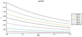
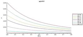
Example: Two spherical shells with inner and outer radius A = 1 m, B = 1.4 m and A = 1 m, B = 1.8 are considered in this case. pi is the applied internal pressure and it is considered  = 0.3 and = 0.5. We use equation (22) to find unknown b for different values of m. We use reinforced neo-Hookean strain energy function with variable material constant. Distributions of extension ratio, deformed radius, normalized radial and normalized hoop stress and normalized maximum shear stress for different m illustrate in the next figures. Figs.2-5show the distribution of extension ratio through the thickness for different m and for = 0.3 and = 0.5, respectively. Maximum of extension ratio is occurred in the inner radius where body subjected to internal pressure. It decreases through the thickness and its minimum is occurred in the outer radius which is a stress free surface. Moreover, because of increasing material strength by increasing m, extension ratio in each arbitrary radius decreases. Additionally, in each arbitrary pressure, ratio of extension ratios decreases in the radial direction. For example, in the inner surface and = 0.3, ratio of extension ratios for m = 0 and m = 11 is 1.065 but it is only 1.021 in the outer surface. By comparison Fig.2 andFig.3, it is observed that in an arbitrary radius, extension ratio increases by increasing internal pressure. Additionally, it is found out in an arbitrary radius, extension ratio decreases by increasing structure parameter
  .
.

 = 1.8,

Figs. 6-9 illustrate radius of sphere in the current configuration versus radius of sphere in the reference configuration for different m and and for = 0.3 and = 0.5, respectively. Deformed radius in each arbitrary undeformed radius decreases by increasing m. Moreover, by comparing these figures, it is observed deformed radius increases by increasing pressure.
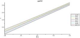
Radius of sphere in the current configuration versus radius of sphere in the reference configuration thickness for different m (
 = 1.4, = 0.3).
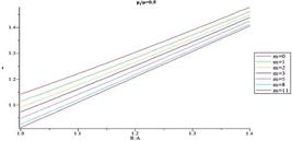
Radius of sphere in the current configuration versus radius of sphere in the reference configuration thickness for different m (
= 1.4, = 0.5).
Radius of sphere in the current configuration versus radius of sphere in the reference configuration thickness for different m (
 = 1.8,
  = 0.3).

Radius of sphere in the current configuration versus radius of sphere in the reference configuration thickness for different m (
= 1.8, = 0.5).
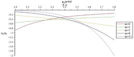
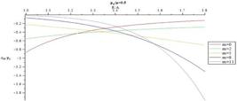
Figs.10-13 present distribution of normalized radial stress through the thickness for different values of m for = 0.3 and = 0.5, respectively. When m decreases magnitude of normalized radial stress in an arbitrary radius decreases. At points away from the boundaries, normalized radial stress shows significant differences for different m, while at points near the boundaries, the reverse holds true. In addition, in each arbitrary radius, increasing internal pressure causes increasing in magnitude of normalized radial. Furthermore, it is understood that in an arbitrary radius by increasing thickness of the pressure vessel  , magnitude of normalized radial stress increases. In addition, in an arbitrary material inhomogeneity parameter (m), decrease rate for magnitude of normalized radial stress in thicker vessel is slower than the thinner one.

Distribution of normalized radial stress through the thickness for different m (
= 1.4,= 0.3).
Distribution of normalized radial stress through the thickness for different m (
= 1.4,= 0.5).
Distribution of normalized radial stress through the thickness for different m and (
= 1.8,= 0.3).

Distribution of normalized radial stress through the thickness for different m and (
= 1.8, = 0.5).
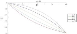
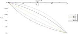
In Figs. 14-17 distribution of normalized hoop stress through the thickness of the vessel for different m are presented for = 0.3 and = 0.5, respectively. Normalized hoop stress in each arbitrary radius increases by increasing internal pressure. Furthermore from the comparison of the Figs. 14-17, it is understood distribution of hoop stress has the same trend for above mentioned shells, but the thicker vessel demonstrates higher hoop stress in an arbitrary radius for the same internal pressure. In fact, it is found that hoop stress increases by increasing structure parameter (B/A). Figs. 18-21 present distribution of normalized maximum shear stress through the thickness for different m. Normalized maximum shear stress has the same distribution as normalized hoop stress. From the comparison of the Figs. 18-21, it is understood distribution of normalized maximum shear stress has the same trend for above mentioned shells, but the thicker vessel demonstrates higher normalized maximum shear stress in an arbitrary radius for the same internal pressure. In fact, it is found that normalized maximum shear stress increases by increasing shell thickness. In contrast with normalized radial stress which has the same distribution for different m, the most interesting part of the results is distribution of normalized hoop stress and normalized maximum shear stress which changing from monotonically decreasing in R to monotonically increasing in R as a function of gradient parameter m. This distribution is very helpful for design of this type of pressure vessel to postpone or avoid vessel failure.

Distribution of normalized hoop stress through the thickness for different m (
= 1.4,= 0.3).

Distribution of normalized hoop stress through the thickness for different m (
= 1.4,= 0.5).

Distribution of normalized hoop stress through the thickness for different m and (
= 1.8,= 0.3).

Distribution of normalized hoop stress through the thickness for different m and (
= 1.8,= 0.5).

Distribution of normalized maximum shear stress through the thickness for different m (
= 1.4,= 0.3).

Distribution of normalized maximum shear stress through the thickness for different m (
= 1.4,= 0.5).
Distribution of normalized shear stress through the thickness for different m and (
= 1.8,= 0.3).
Distribution of normalized shear stress through the thickness for different m and (
= 1.8,= 0.5).
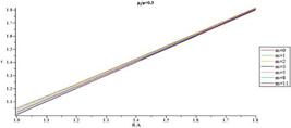
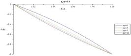
Example 2 (thin sphere): A spherical shell with inner and outer radius A =1 m, B = 1.1 m is considered in this case. The applied internal pressure = 0.1. Equation (22) is solved to find b by considering = 1.1. In this case, pressure vessel is classified as a thin pressure vessel. Extension ratio of this vessel decrease approximately linearly with R, as shown inFig. 22. In Fig.23 radius of sphere in the current configuration versus radius of sphere in the reference configuration is shown. Fig. 24, 25 and 26 demonstrate distribution of radial, hoop and shear stresses of this vessel.


Radius of sphere in the current configuration versus radius of sphere in the reference configuration thickness for different m (
= 1.1, = 0.1).
Distribution of normalized radial stress through the thickness for different m (
= 1.1,= 0.1).
Distribution of normalized hoop stress through the thickness for different m (
= 1.1,= 0.1).

Distribution of normalized shear stress through the thickness for different m (
= 1.1,= 0.1).
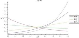
Example 3: Two spherical shells with inner and outer radius A = 1 m, B = 1.4 m and A =1 m, B = 1.8 are considered in this case. The applied external pressure is po. In this example, we considered  = 0.3 and = 0.5. b is calculated for different values of m by using equation (22). Reinforced neo-Hookean strain energy function with variable material constant is used in this example. Distributions of extension ratio, deformed radius, radial and hoop stress and maximum shear stress for different m illustrate in the next figures. Figs.27-30show the distribution of extension ratio versus undeformed radius for different m for above mentioned vessels. Minimum of extension is occurred in the inner radius of the vessel then it increases through the thickness and its maximum is happened in outer radius. Moreover, by increasing material inhomogeneity (m) parameter, extension ratio in each arbitrary radius increases. Additionally, in each arbitrary pressure, ratio of extension ratios increases in the radial direction. For example, in the inner surface and
  = 0.3, ratio of extension ratios for m = 0 and m = 11 is 0.953 but it is 0.981 in the outer surface. By comparison Figs.27-30, it is observed that in an arbitrary radius extension ratio decreases by increasing external pressure. Furthermore, it is observed that extension ratio increases by increasing structure parameter
  . It means that by increasing shell thickness , radial deformation decreases. In Fig.31-34 radius of sphere in the current configuration versus radius of sphere in the reference configuration is shown.


Radius of sphere in the current configuration versus radius of sphere in the reference configuration thickness for different m(
 = 1.4,
 = 0.3).

Radius of sphere in the current configuration versus radius of sphere in the reference configuration thickness for different m(
= 1.4,= 0.5).

Radius of sphere in the current configuration versus radius of sphere in the reference configuration thickness for different m(
 = 1.8,
 = 0.3).

Radius of sphere in the current configuration versus radius of sphere in the reference configuration thickness for different m(
= 1.8,= 0.5).
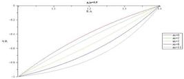
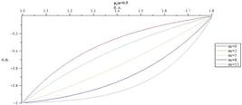
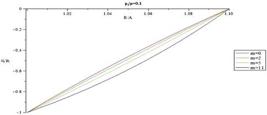
In Figs. 35-38, normalized radial stress through the thickness for different m is illustrated. Magnitude of normalized radial stress in each radius decreases by increasing m. At points away from the boundaries, normalized radial stress shows significant differences for different m, while at points near the boundaries, the reverse holds true. Additionally in each arbitrary radius, magnitude of normalized radial stress increases by increasing external pressure. Magnitude of normalized radial stress decreases in an arbitrary radius as structure parameter increases. In addition, increase rate of magnitude of normalized radial stress in thicker vessel is slower than the thinner one.
Distribution of normalized radial stress through the thickness for different m(
= 1.4,= 0.3).
Distribution of normalized radial stress through the thickness for different m(
= 1.4,= 0.5).

Distribution of normalized radial stress through the thickness for different m(
= 1.8,= 0.3).

Distribution of normalized radial stress through the thickness for different m(
= 1.8,= 0.5).
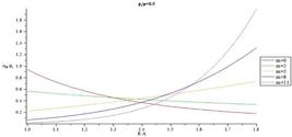
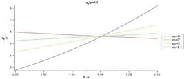
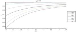
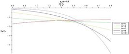
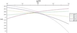
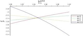
In Figs. 39-42 distribution of normalized hoop stress versus radius for different m is presented. Figs. 43-46 presents distribution of normalized maximum shear stress through the thickness for different m. Normalized maximum shear stress has the same pattern of distribution as normalized hoop stress.

Distribution of normalized hoop stress through the thickness for different m(
= 1.4,= 0.3).

Distribution of normalized hoop stress through the thickness for different m(
= 1.4,= 0.5).

Distribution of normalized hoop stress through the thickness for different m(
= 1.8,= 0.3).
Distribution of normalized hoop stress through the thickness for different m(
= 1.8,= 0.5).
Distribution of normalized maximum shear stress through the thickness for different m(
= 1.4,= 0.3).

Distribution of normalized maximum shear stress through the thickness for different m(
= 1.4,= 0.5).
Distribution of normalized shear stress through the thickness for different m(
= 1.8,= 0.3).
Distribution of normalized shear stress through the thickness for different m(
= 1.8,= 0.5).
Example 6 (thin sphere): A spherical shell with inner and outer radius A = 1 m, B = 1.1 m is be considered in this case. The applied external pressure is = 0.1. Equation (22) is solved to find b by considering = 1.1. In this case, pressure vessel is classified as a thin pressure vessel. Extension ratio of this vessel increase approximately linearly with R as shown inFig. 47. In Fig.48 radius of sphere in the current configuration versus radius of sphere in the reference configuration is shown. Fig. 49, 50 and 51 demonstrate distribution of radial, hoop and shear stresses of this vessel.


Radius of sphere in the current configuration versus radius of sphere in the reference configuration thickness for different m(
= 1.1,= 0.1).
Distribution of normalized radial stress through the thickness for different m(
= 1.1,= 0.1).

Distribution of normalized hoop stress through the thickness for different m(
= 1.1,= 0.1).
Distribution of normalized shear stress through the thickness for different m(
= 1.1,= 0.1).
4 CONCLUSION
In this paper, we use member of Ericksen's family of universal solutions to investigate radial expansion/contraction of a sphere made of transversely isotropic and inhomogeneous hyperelastic material. Reinforced neo-Hookean strain energy function is used to model material behavior. The material parameter varues continuously in radial direction according to a power law in the radial coordinate "R" in the reference configuration. Analytical method is used to find Stress components and stretches in thick-walled spherical shells subjected to internal and external pressure. As a result stress components and stretches versus Radial direction are plotted for different pressure and different structural parameter and different material inhomogeneity parameter and effect of these parameters are studied carefully in stress component distribution.
In the internally pressurized sphere, magnitude of radial stress, extension ratio and radius of sphere increase when pressure increases. By increasing material inhomogeneity parameter (m), in each arbitrary pressure and radius, magnitude of radial stress increases while extension ratio and sphere radius decrease. Increasing structural parameter  causes decrease in extension ratio and increase in magnitude of normalized radial stress. In addition, in each arbitrary material inhomogeneity parameter (m), decrease rate of magnitude of radial stress in thicker vessel decreases is slower than the thinner one.
We consider same plots for sphere subjected to external pressure. It is found that, in each arbitrary radius, increase in applied external pressure causes increase in magnitude of normalized radial stress and decrease in extension ratio and deformed sphere radius. In an arbitrary external pressure, when material inhomogeneity parameter (m) increases, extension ratio and sphere radius increase but magnitude of normalized radial stress decreases. Increase in pressure vessel thickness causes decrease in radial stress in an arbitrary applied pressure. It is also observed that by increasing thickness of pressure vessel  , extension ratio increases while magnitude of normalized radial stress decreases. Furthermore, it is observed that in each arbitrary material inhomogeneity parameter (m), increase rate of normalized magnitude of radial stress in thicker vessel is slower than the thinner one.
In contrast with normalized radial stress which has the same distribution for different m, the most interesting part of the results is distribution of normalized hoop stress and normalized maximum shear stress which changing from monotonically increasing in R to monotonically decreasing in R as a function of gradient parameter m.
The above results show that the material inhomogeneity parameter (m) and pressure vessel thickness have a significant influence on the mechanical behavior of thick hollow spherical shells made of transversely isotropic functionally graded hyperelastic materials with power law varying properties. Thus with selecting a proper m value and structure parameter , engineers can design a specific FGM hollow sphere that can meet some special requirements.
References
- Anani, Y. and Alizadeh, Y., (2011), Visco-hyperelastic constitutive law for modeling of foam's behavior, J of Material & Design 32(5):2940-2948.
- Arfken, G., (1985),Mathematical methods for physicists, third ed., Academic Press, Orlando, FL.
- Attard,M.M. (2003), Finite strain-isotropic hyperelasticity. International Journal of Solids and Structures 40(17): 4353-4378.
- Bao R.H., Xue P., Yu T.X., Tao X.M. TAO (2003) Numerical simulation of large deformation of flat-topped conical shells made of textile, Latin American Journal of Solid and Structures 1:25-47.
- Batra, R.C. and Bahrami, A., (2003) Inflation and eversion of functionally graded nonlinear elastic incompressible cylinders, Int. J. of Non-Linear Mechanics, 44: 311-323.
- Batra, R.C., (2006), Torsion of a functionally graded cylinder. AIAA J, 44:1363-1365.
- Beatty,M.F., (1987) Topics in finite elasticity: hyperelasticity of rubber, elastomers, and biological tissues-with examples. Applied Mechanics Review 40(12): 1699-1735.
- Bilgili, E., (2003), Controlling the stress-strain inhomogeneities in axially sheared and radially heated hollow rubber tubes via functional grading, Mech. Res. Commun. 30:257-66.
- Bilgili, E., (2004), Modelling mechanical behaviour of continuously graded vulcanized rubbers., Plast Rubbers Compos 33(4):163-169.
- Bilgili, E., Bernstein, B., Arastoopour, H., (2002), Influence of material non-homogeneity on the shearing response of a neo-Hookean slab. Rubber Chem Technol. 75(2):347-363.
- Brünig M.,(2004), An anisotropic continuum damage model: theory and numerical analyses, Latin American Journal of Solid and Structures 2:185-218.
- Ericksen, J.L. and Rivlin R.S., (1954), Large elastic deformations of homogeneous anisotropic materials, J. Rational Mech. Anal., 3:281-301.
- Ericksen, J.L., (1954), Deformations possible in every isotropic incompressible perfectly elastic body, Z. Angew. Math. Phys. 5:466-486.
- Fu,Y.B. and Ogden,R.W.,(2001) Nonlinear Elasticity. Cambridge University Press.
- Ghannad, M. and Nejad, M. Z., (2012), Complete closed-form solution for pressurized heterogeneous thick spherical shells, Mechanika, 18(5):508-516.
- Gharooni H., Ghannad M., (2015), Elastic analysis of pressurized thick fgm cylinders with exponential variation of material properties using tsdt, Latin American Journal of Solid and Structures 12: 1024-1041.
- Ghasemi, F.A., Malekzadeh fard, K., Azarnia, A., (2015), High order impact elastic analysis of circular thick cylindrical sandwich panels subjected to multi-mass impacts, Latin American Journal of Solid and Structures 12: In press.
- Horgan,C.O. and Polignone,D.A. (1998), Cavitation in nonlinearly elastic solids: A review. Applied Mechanics Review 48(8): 471-485.
- Ikeda, Y, Kasai, Y., Murakami, S., Kohjiya, S., (1998), Preparation and mechanical properties of graded styrene-butadiene rubber vulcanizates, J. Jpn. Inst. Metals, 62: 1013-1017.
- Nie, G., Zhong, Z., Batra, R., (2011), Material tailoring for functionally graded hollow cylinders and spheres, Comp. Sci. Tech. 71:666-673.
- Pascon J.P. and Coda H.B., (2013), Large deformation analysis of homogeneous rubber-like materials via shell finite elements, Latin American Journal of Solid and Structures 10:1177-1210.
- Reddy, J.N.(2007), Theory and Analysis of Elastic Plates and Shells, Boca Raton: CRC Press, 403p.
- Spencer, A.J.M., (1984), Continuum theory of the mechanics of fibre-reinforced composites, CISM Courses and Lecture Notes No. 282.
- Dorfmann, A., Ogden, R.W. (2004), A constitutive model for the Mullins effect with permanent set in particle-reinforced rubber, Int. J. Solids Struct. 41: 1855-1878.
Publication Dates
-
Publication in this collection
Mar 2016
History
-
Received
14 Aug 2015 -
Reviewed
05 Dec 2015 -
Accepted
07 Dec 2015

 Thumbnail
 Thumbnail
 Thumbnail
 Thumbnail
 Thumbnail
 Thumbnail
 Thumbnail
 Thumbnail
 Thumbnail
 Thumbnail
 Thumbnail
 Thumbnail
 Thumbnail
 Thumbnail
 Thumbnail
 Thumbnail
 Thumbnail
 Thumbnail
 Thumbnail
 Thumbnail
 Thumbnail
 Thumbnail
 Thumbnail
 Thumbnail


