Abstract
In this paper, a new loading device was employed to conduct a mixed-mode fracture test. Therefore, disadvantages detected in the previous mixed-mode fracture toughness test methods can be avoided. The new fixture has perfect symmetry which provides a uniform stress state, creates the pure plane strain conditions and eliminates the unwanted mode-III loading conditions. The values of non-dimensional stress intensity factors for pure mode-I, pure mode-II, and pure mode-III were obtained using 3D models of new loading device and modified Arcan method in order to compare the results and investigate the variation of fracture parameters. Furthermore, the values of correction factors for pure mode-III in various loading angles were studied for both fixtures and it was resulted that in modified Arcan device there was a larger contribution of unwanted third mode loading conditions and therefore the values of mode-I and mode-II non-dimensional stress intensity factors were affected. In the present study, in order to compare the results, the fracture toughness values of ABS (Acrylonitrile butadiene styrene) polymeric material were determined experimentally for both fixtures and a full range of mixed-mode loading conditions including pure mode-I and pure mode-II loading were created and tested. The differences in critical stress intensity factors of the fixtures were found about 7.00% and 42.65% in mode-I and mode-II loading conditions, respectively.
Keywords:
Fracture toughness testing; Mixed-mode I/II fracture; Experimental analysis; Modified loading device; Finite-element analysis
1 INTRODUCTION
Characterizing fracture toughness is an effective factor in determining the fracture of materials. In recent years, many test methods have been used by many researchers to determine fracture toughness for three modes of loading (I, II and III) and also under mixed-mode loading conditions. Some of these methods include: the double cantilever beam (DCB) and the end notched flexure (ENF) specimens have been employed for mode-I and mode II tests, respectively (Davidson et al., 2012Davidson, P., Waas, A.M., Yerramalli, C.S. (2012). Experimental determination of validated, critical interfacial modes I and II energy release rates in a composite sandwich panel, Composite Structures 94: 477-483, doi:10.1016/j.compstruct.2011.08.007.
https://doi.org/10.1016/j.compstruct.201...
, Shokrieh and Heidari, 2011Shokrieh, M.M., Heidari-Rarani, M. (2011). Effect of stacking sequence on R-curve behavior of glass/epoxy DCB laminates with 0°//0° crack interface, Materials Science and Engineering 529: 265-269, doi:10.1016/j.msea.2011.09.027.
https://doi.org/10.1016/j.msea.2011.09.0...
, Zacharopoulos, 2004Zacharopoulos, D.A. (2004). Stability analysis of crack path using the strain energy density theory, Theoretical and Applied Fracture Mechanics 41: 327-337, doi:10.1016/j.tafmec.2003.11.018.
https://doi.org/10.1016/j.tafmec.2003.11...
). A crack rail shear (CRS) specimen has been proposed to determine the mode-III (tearing) critical strain energy release rate by (Becht and Jr, 1988Becht, G., Jr, W. G. (1988). Design and analysis of the crack rail shear specimen for mode III interlaminar fracture, Composites Science and Techology 31: 143-157, doi:10.1016/0266-3538(88)90088-7.
https://doi.org/10.1016/0266-3538(88)900...
). The mixed-mode bending (MMB) test has been proposed by combining the schemes used for DCB and ENF tests, which can produce a wide range of the ratios of mode-I and mode-II components by varying the lever arm of the specimen. A modified MMB test method was used for evaluation of the interlaminar fracture toughness of AS4/PEEK composite material by (Reeder, 1990Reeder, J.R. (1990). 3D Mixed-Mode Delamination Fracture Criteria-An Experimentalist's Perspective, NASA Langley Research Center, M/S 188E, Hampton, VA 23681-2199, USA. http://ntrs.nasa.gov/archive/nasa/casi.ntrs.nasa.gov/20060048260.pdf.
http://ntrs.nasa.gov/archive/nasa/casi.n...
), (Reeder and Crews, 1990Reeder, J.R., Crews, J.R. (1990). Mixed-Mode Bending Method for Delamination Testing, AIAA J. 28, 1270-1276.). Furthermore, MMB test method was recently used for investigation of crack propagation in adhesively bonded joints by (Ben Salem et al., 2014Ben Salem, N., Jumel, J., Budzik, M.K., Shanahan, M.E.R., Lavelle, F. (2014). Analytical and experimental investigations of crack propagation in adhesively bonded joints with the Mixed Mode Bending (MMB) test Part I: Macroscopic analysis & Digital Image Correlation measurements, Theoretical and Applied Fracture Mechanics 74: 209-221, doi:10.1016/j.tafmec.2014.05.006.
https://doi.org/10.1016/j.tafmec.2014.05...
). Researchers like (Verma et al., 1995Verma, S.K., Kumar, P., Kishore, N.N. (1995), Evaluation of critical interlaminar sif of DCB specimen made of slender cantilever, Engineering Fracture Mechanics 50: 345-353, doi:10.1016/0013-7944(94)00204-U.
https://doi.org/10.1016/0013-7944(94)002...
) and (Dharmawan et al., 2006Dharmawan, F., Simpson, G., Herszberg, I., John, S. (2006). Mixed mode fracture toughness of GFRP composites, Composite Structures 75: 328-338, doi:10.1016/j.compstruct.2006.04.020.
https://doi.org/10.1016/j.compstruct.200...
) evaluated the fracture toughness of composite materials by using DCB, ENF and MMB specimens. However, for all these test methods there are problems in that a wide range of mixed-mode ratios cannot be tested which limits their usefulness (Reeder and Crews, 1990Reeder, J.R., Crews, J.R. (1990). Mixed-Mode Bending Method for Delamination Testing, AIAA J. 28, 1270-1276.). But in order to obtain reliable results for interlaminar fracture toughness for pure mode-I, pure mode-II, and mixed-mode loading conditions, different beam type specimens would be required. It is therefore necessary to develop other test methods to evaluate the interlaminar fracture parameters of materials under all in-plane loading conditions starting from pure mode-I to pure mode-II. In recent years, many researchers have been used different loading devices for evaluation of the fracture toughness of materials like (Ban et al., 2015Ban, H., Im, S., Kim, Y. (2015). Mixed-mode fracture characterization of fine aggregate mixtures using semicircular bend fracture test and extended finite element modeling, Construction and Building Materials 101: 721-729, doi: 10.1016/j.conbuildmat.2015.10.083.
https://doi.org/10.1016/j.conbuildmat.20...
), (Choupani et al., 2015Choupani, M., Ayatollahi, M. R., Mallakzadeh, M. (2015). Investigation of Fracture in an Interface Crack Between Bone Cement and Stainless Steel, Latin American Journal of Solids and Structures 12: 446-460, doi: 10.1590/1679-78251142.
https://doi.org/10.1590/1679-78251142...
), (Nunes and Reis, 2014Nunes, L.C.S., Reis, J.M.L. (2014). Experimental investigation of mixed-mode-I/II fracture in polymer mortars using digital image correlation method, Latin American Journal of Solids and Structures 11: 330-343.), (Silva et al., 2016Silva, F.G.A., de Moura, M.F.S.F., Dourado, N., Xavier, J., Pereira, F.A.M., Morais, J.J.L., Dias, M.I.R. (2016). Mixed-mode I+II fracture characterization of human cortical bone using the Single Leg Bending test, Journal of the Mechanical Behavior of Biomedical Materials 54: 72-81, doi: 10.1016/j.jmbbm.2015.09.004.
https://doi.org/10.1016/j.jmbbm.2015.09....
). A modified version of Arcan specimen has been made for the mixed-mode fracture test of adhesively bonded joints, which allows pure mode-I, pure mode-II, and almost any combination of mode-I and mode-II loading to be tested using the same test specimen configuration by (Arcan et al., 1978Arcan, M., Hashin, Z., Voloshin, A. (1978). A Method to Produce Uniform Plane-stress States with Applications to Fiber-reinforced Materials, Experimental Mechanics 18: 141-146, doi:10.1007/BF02324146.
https://doi.org/10.1007/BF02324146...
) and several studies have been done using Arcan specimen like (Ayatollahi and Sedighiani, 2012Ayatollahi, M.R., Sedighiani, K. (2012). A T-stress controlled specimen for mixed mode fracture experiments on brittle materials, European Journal of Mechanics -A/Solids 36: 83-93, doi:10.1016/j.euromechsol.2012.02.008.
https://doi.org/10.1016/j.euromechsol.20...
), (Cognard et al., 2008Cognard, J.Y., Créac'hcadec, R.C., Sohier, L., Davies, P. (2008). Analysis of the nonlinear behavior of adhesives in bonded assemblies-Comparison of TAST and Arcan tests, International Journal of Adhesion and Adhesives 28: 393-404, doi:10.1016/j.ijadhadh.2008.04.006.
https://doi.org/10.1016/j.ijadhadh.2008....
), (Nikbakht and Choupani, 2009Nikbakht, M., Choupani, N. (2009). Experimental investigation of mixed-mode fracture behavior of woven laminated composite, Journal of Materials Science 44: 3428-3437, doi:10.1007/s10853-009-3456-1.
https://doi.org/10.1007/s10853-009-3456-...
), (Heydari et al., 2011Heydari, M.H., Choupani, N., Shameli, M. (2011). Experimental and Numerical Investigation of Mixed-Mode Interlaminar Fracture of Carbon-Polyester Laminated Woven Composite by Using Arcan Set-up, Applied Composite Materials 18: 499-511, doi:10.1007/s10443-011-9223-x.
https://doi.org/10.1007/s10443-011-9223-...
). However, modified Arcan fixture has several problems which limit its usefulness (Greer Jr et al., 2011Greer Jr, J.M., Galyon Dorman, S.E., Hammond, M.J. (2011). Some comments on the Arcan mixed-mode (I/II) test specimen, Engineering Fracture Mechanics 78: 2088-2094, doi:10.1016/j.engfracmech.2011.03.017.
https://doi.org/10.1016/j.engfracmech.20...
, Pucillo et al., 2011Pucillo, G.P., Grasso, M., Penta, F., Pinto, P. (2011). On the mechanical characterization of materials by Arcan-type specimens, Engineering Fracture Mechanics 78: 1729-1741, doi:10.1016/j.engfracmech.2011.02.002.
https://doi.org/10.1016/j.engfracmech.20...
, Song and Huh, 2011Song, J.H., Huh, H. (2011). Failure characterization of spot welds under combined axial-shear loading conditions, International Journal of Mechanical Sciences 53: 513-525, doi:10.1016/j.ijmecsci.2011.04.008.
https://doi.org/10.1016/j.ijmecsci.2011....
). One of the most important problems is the specimen-fixture connection which causes bending or unwanted third mode loading conditions (Figure 1). This problem had been mentioned by (Hosseini et al., 2008Hosseini, S.R., Choupani, N., Gharabaghi, A.R.M. (2008). Experimental Estimation of Mixed-Mode Fracture Properties of Steel Weld, International Journal of Civil, Environmental, Structural, Construction and Architectural Engineering 2: 86-91.), (Cognard et al., 2011Cognard, J.Y., Sohier, L., Davies, P. (2011). A modified Arcan test to analyze the behavior of composites and their assemblies under out-of-plane loadings, Composites Part A: Applied Science and Manufacturing 42: 111-121, doi:10.1016/j.compositesa.2010.10.012.
https://doi.org/10.1016/j.compositesa.20...
). In this research, in order to obtain reliable results of fracture parameters, correction factors of new designed fixture and modified Arcan fixture were determined using three-dimensional finite element analysis. As the results, in the new fixture, a mode-III loading condition was eliminated, and the obtained results were compared based on characterizing the fracture toughness of ABS polymeric material for both cases experimentally.
In this study, a new loading device was made for the mixed-mode fracture test of specimens, which allows mode-I, mode-II, and almost any combination of mode-I and mode-II loading to be tested with the same test specimen configuration (Figure 2). The test specimen was developed to produce a uniform state of plane-stress in solid specimens, where the grips and the butterfly specimen are cut out of a single plate. Thus, no joints were necessary between the butterfly specimen and the grips. The main component of the apparatus is a butterfly specimen, which is inserted on either side to two half-circular grips. The grips are connected to a universal testing machine at the top and bottom, respectively. The grips together with the butterfly specimen form a circular disk with two anti-symmetric cutouts. The scaled locations on the outer edge of the fixture provide a range of loading angles (Figure 2). The specimen is loaded by pulling apart grips of the fixture at a pair of grip on the opposite sides of a scaled radial line. By varying the loading angle α, all mixed-mode conditions starting from pure mode-I to pure mode-II can be created and tested. It is a simple test procedure, clamping/unclamping the specimens is easy to achieve and only one type of specimen is required to generate all loading conditions. Therefore, disadvantages presented in the previous mixed-mode fracture toughness test methods can be avoided. The new fixture has perfect symmetry which provides a uniform stress state, creates the pure plane strain conditions and eliminates the unwanted mode-III loading conditions.
Schematic configuration of new loading device and specimen (Es'hagi Oskui et al., 2013Es'hagi Oskui, A., Choupani, N., Haddadi, E. (2013). Experimental & Numerical Investigation of Fracture of ABS Polymeric Material for Different Sample's Thickness Using a New Loading Device, Polymer Engineering & Science 54: 2086-2096, doi:10.1002/pen.23745.
https://doi.org/10.1002/pen.23745... ).
2 AN OVERVIEW OF FRACTURE MECHANICS
The purpose of fracture toughness testing is to determine the value of the critical stress intensity factor, or plane strain fracture toughness KC. This material property is used to characterize the resistance to fracture in the design of structural members. ASTM standards E399 and D5045 give some guidance for plane strain mode-I fracture toughness for metals and plastics, respectively. No standard requirements exist for the validity of linear elastic fracture mechanics and plane-strain conditions for tests with polymeric materials under mode-II and mixed-mode loading conditions. Therefore, it may be necessary to develop tests tailored for use with polymeric materials in order to investigate the role of mixed-mode loading conditions. This investigation seeks to extend understanding of the polymeric materials fracture behavior under mixed-mode loading conditions through numerical and experimental analysis. Using finite element results, correction factors were applied to the specimen and a polynomial fit was proposed to evaluate the stress intensity factors of the specimen with a crack subjected to mixed-mode loading conditions. The research conducted for this study assumed that the polymeric material under consideration was homogenous and linear elastic. The main objective of this study was to determine the fracture toughness KIC and KIIC for the polymeric materials under consideration for a wide range of mixed-mode loading with assumption of linear elastic conditions according ASTM D5045 standards, in which linear elastic fracture mechanics and plane strain conditions are the primary requirements. During this research several issues remained beyond the scope of this work. However, the effect of direction of the anisotropy in the specimens on the performance of material must also not be ignored. To accurately understand the durability of polymeric materials, it is necessary to have knowledge of the effect of mechanical anisotropy influences on the magnitudes of fracture toughness values. For example, the anisotropy may affect the applicability of linear elastic fracture mechanics criterion and increase the fracture toughness. Also, some degree of future work should focus on investigating alternate approach using elastic-plastic fracture mechanics in the polymeric materials and incorporating this information along with the influence of anisotropy into finite element models.
The main problem of predicting the failure of materials is to characterize the values of fracture toughness especially under mixed-mode loading conditions. Linear elastic fracture mechanics has been found a useful tool for investigating of cracks in materials. Figure 3 shows an element near the tip of a crack in an elastic material, under the in plane stresses on this element. It is noted that each stress component is proportional to a single constant, K. That is mathematically analyzable, and it characterizes the stress and displacement distributions at the crack tip, and it also characterizes the behavior and the criticality of the crack. The solution for K consists of terms representative of stress (or load), crack length, and geometry. It fully accounts for the geometry of a local area in a structure in question, the crack morphology, and how the load is applied (Anderson, 2005Anderson, T.L. (2005). Fracture mechanics fundamentals and applications, third ed. CRC Press, Texas.). This constant factor, which is called the stress intensity factor, completely characterizes the crack tip conditions in a linear elastic material. It does refer to a specific zone near the crack tip, as shown in Figure 3. In this zone, the stress field is completely described by the stress intensity factor, KI or KII , and the stresses are given by the following equations respectively for mode-I (Equations 1a) and mode-II (Equations 1b) (Anderson, 2005Anderson, T.L. (2005). Fracture mechanics fundamentals and applications, third ed. CRC Press, Texas.):


where, r and θ are polar coordinates shown in Figure 3.
Crack propagation may be accomplished in opening-mode (mode-I), shearing-mode (mode-II), tearing mode (mode-III) and their combinations. The purpose of fracture toughness testing is to determine the value of the critical stress intensity factor, or plane strain fracture toughness KC . This material property is used to characterize the resistance to fracture in the design of structural members. ASTM standards E399 and D5045 give some guidance for plane strain mode-I fracture toughness KIC for metals and plastics. The stress intensity factor KC at the tip of a crack in a compact tension specimen is given by:

where PC
is the fracture load, a is crack length, w is the specimen width, t is the specimen thickness, and f (a/w) is a geometrical factor. According ASTM standards E399 and D5045, the computed KC
value may turn out to be the critical stress intensity factor, or fracture toughness only if all the validity requirements were met. Linear elastic fracture mechanics is the primary requirement, i.e. linear elastic material behaviour of the cracked specimen on the load-displacement diagram. Second, the conditions for plane strain at the crack-tip must also be checked; if specimen thickness is not sufficient to ensure this stress state, then it is rather more plane-stress than plane-strain, and the fracture toughness will be larger than the actual plane-strain value. The thickness and crack length must be sufficient to ensure the plane-strain conditions; ASTM requirements are: 0.45 〈a / w 〈0.55, t, a ≥ 2.5 σy
is the yield , where
strength of the material being tested. The stress intensity factors ahead of the crack tip for mixed mode loading conditions can be calculated using the following equations (Sih and Theocaris, 1980Sih, G.C., Theocaris, P.S. (1981). Mixed mode crack propagation, Proceedings of the First USA-Greece Symposium on Mixed Mode Crack Propagation: held at the Athens National Technical University, Athens, Greece, ISBN 9028626913, http://trove.nla.gov.au/version/30825171.
http://trove.nla.gov.au/version/30825171...
; Gdoutos, 2005Gdoutos, E.E. (2005). Fracture Mechanics, second ed. Springer, Greece.):

where fI (a/w), fII (a/w), and fIII (a/w) are the geometrical factors and are obtained using finite element analysis. Furthermore stress intensity factors can be related to the strain energy release ratios (J-Integral) for liner elastic materials:

where E' = E for plane stress, E' = E/(1-ν2) for plane strain conditions, E is modulus of elasticity, ν is Poisson's ratio. The calculated strain energy release rate values are indications of cracked polymeric material durability, by quantitatively showing how much energy must be put into the specimen to create fracture.
3 FINITE ELEMENT ANALYSIS
The stress intensity factors KI , KII , and KIII play an important role in linear elastic fracture mechanics. They characterize the influence of the load or deformation on the magnitude of crack tip stress and strain fields and measure the propensity of the crack propagation or the crack driving forces. Furthermore, the stress intensity factor can be related to the energy release rate (the J-integral) for a linear elastic material:

where K = [KI KII KIII]T and B is called the pre logarithmic energy factor matrix. In order to calculate the stress intensity factors, interaction integral method is commonly used.
The method is applicable to cracks in isotropic and anisotropic materials. Based on the definition of the J-integral, the interaction integrals can be expressed as (ABAQUS, V 6.7 2007ABAQUS V 6.7. (2007). User's Manual. Dassault Systemes Simulia Corp., Providence, Rhode Island.):

where Г is an arbitrary contour, q is a unit vector in the virtual crack extension direction, n is the outward normal to Г, σ is the stress tensor and u the displacement vector. The subscript aux represents three auxiliary pure mode-I, mode-II, and mode-III crack-tip fields for α = I, II, and III, respectively. The domain form of the interaction J-integral is:

where λ(s) is the virtual crack advance and dA is the surface element. Several contours integral evaluations are possible at each location along a crack. In a finite element model, each evaluation could be thought of as the virtual motion of a block of material surrounding the crack tip (in two dimensions) or surrounding each node along the crack line (in three dimensions). Each contour provides an evaluation of the contour integral. The number of possible evaluations is the number of such rings of elements. Figure 4 shows contours surrounding the crack tip.
Contour integral around the crack tip (ABAQUS, V 6.7 2007ABAQUS V 6.7. (2007). User's Manual. Dassault Systemes Simulia Corp., Providence, Rhode Island.).
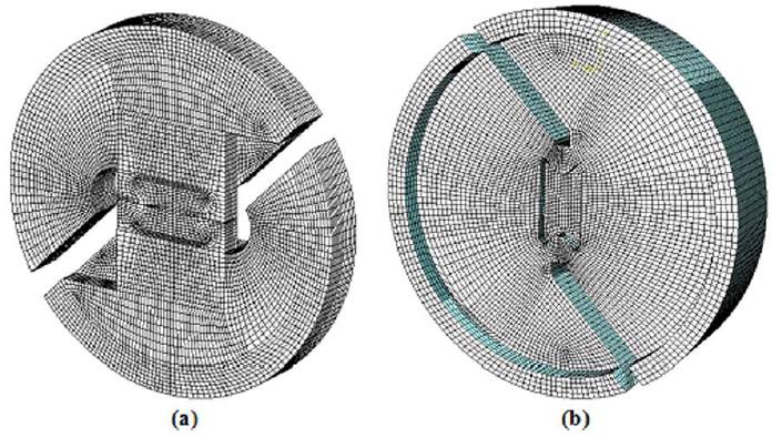
For the purpose of estimation of correction factors of the specimens in real conditions, 3D model of test apparatus was created by SOLIDWORKS software and was modeled by ABAQUS finite element software. Quadrilateral twenty node elements were used and mesh was refined around the crack tip (Figure 5). In 3D model in order to obtain the 1/√r singularity term of the crack tip stress field, which is necessary for linear elastic finite element analysis, elements around the crack tip were focused on the crack tip and the mid-side nodes were moved to a quarter point of each element side. Analyses were performed with ABAQUS under a constant load of 1,000 N and crack length ratio of 0.5. Total number of elements applied in this model was approximately 80000 elements.
Three-dimensional finite element model of (a) modified Arcan loading device, and (b) new loading device.
4 TEST METHOD AND SETUP
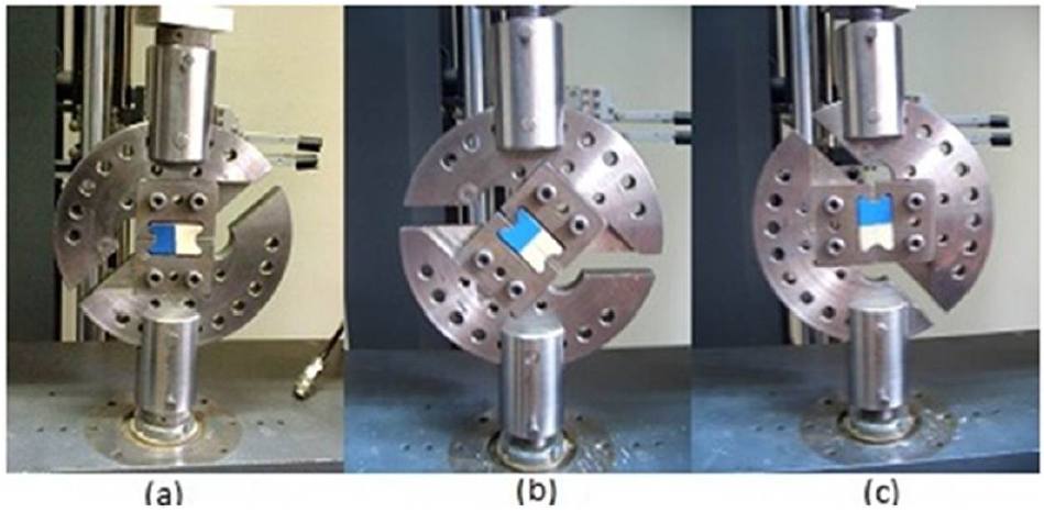
The new loading device and modified version of Arcan specimen are shown in Figures 6 and 7, respectively. A compact fracture mechanics specimen was used for the determination of fracture toughness under mode-I, mode-II and mixed-mode loading conditions and the loading device was installed in the universal testing machine. The specimen is loaded by pulling apart grips of the fixture at a pair of grip holes on the opposite sides of a radial line. By varying the loading angle, all mixed-mode conditions starting from pure mode-I to pure mode-II can be created and tested.
Overview of test rig and set up of the new fixture: (a) mode-I, (b) mixed-mode, (c) mode-II.
ASTM standards E399 and D5045 give some guidance for test conditions for metals and plastics, respectively. Fracture tests were conducted in room temperature and by controlling the constant displacement rate of 0.5 mm/min according ASTM D5045 standard and the fracture loads and displacements were recorded. Tests were repeated at least three times for each loading angle, and total of 18 specimens were tested in this survey.
Overview of test rig and set up of modified Arcan fixture: (a) mode-I, (b) mixed-mode, (c) mode-II.
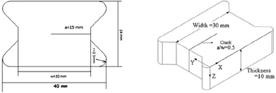
The load-displacement curves generated by the test machine were used to determine maximum loads and displacements. The average values of critical fracture loads were used in order to determine the critical mixed-mode stress intensity factors. Experimental efforts focused on the mixed-mode fracture of tests of ABS polymer with modulus of elasticity of 1.78 GPa, the Poisson's ratio of 0.4, and the crack length ratio of a/w=0.5 (Figure 8). The ABS polymeric material investigated for this study were chosen based upon its availability or anticipated usage on industrial applications. By varying the loading angle α (α=0(, 45(, 90(), pure mode-I, pure mode-II and mixed-mode conditions can be created and tested. The mixed-mode fracture experiments were conducted to determine the fracture toughness of ABS polymeric material using the new fixture and modified Arcan test methods and the results were compared.
5 RESULTS AND DISCUSSION
5.1 Numerical Results
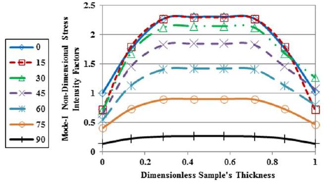
In this study, the values of non-dimensional stress intensity factors for pure mode-I, pure mode-II, and pure mode-III was obtained using 3D models for mixed-mode loading conditions of the two fixtures in order to compare the results and investigate the variation of fracture parameters. As shown in Figures 9 and 10, values of mode-I and mode-II non-dimensional stress intensity factors versus dimensionless sample's thickness of modified Arcan loading device shows a non-uniform distribution of stress intensity factor on the samples which causes bending or unwanted third mode loading conditions. In contrast, according to perfect symmetry of new loading device, there is a uniform distribution of stress intensity factor on the thickness of samples in the regions of far from boundary conditions (Figures 11 and 12).
Mode-I non-dimensional stress intensity factors of modified Arcan loading device versus dimensionless sample's thickness for different mixed-mode loading conditions.
Mode-II non-dimensional stress intensity factors of modified Arcan loading device versus dimensionless sample's thickness for different mixed-mode loading conditions.
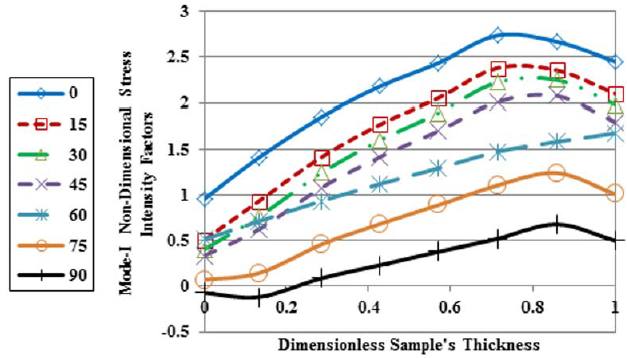
Mode-I non-dimensional stress intensity factors of new loading device versus dimensionless sample's thickness for different mixed-mode loading conditions.
Mode-II non-dimensional stress intensity factors of new loading device versus dimensionless sample's thickness for different mixed-mode loading conditions.
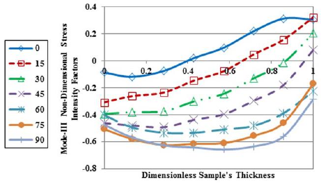
In addition, by using a 3D model, values of mode-III non-dimensional stress intensity factors versus dimensionless thickness were obtained for modified Arcan loading device and new loading device. As shown in the Figures 13 and 14, values of mode-III in modified Arcan loading device are high. Furthermore, it can be seen that by increasing loading angle, the values of mode-III non-dimensional stress intensity factors increase, and therefore it can be resulted that values of fracture parameters resulted from modified Arcan loading device for loading conditions especially near to mode-II are unrealistic. In contrast, according to Figure 14, average values of mode-III non-dimensional stress intensity factors resulted from new loading device are negligible that it is confirmed due to the perfect symmetry of new loading device.
Mode-III non-dimensional stress intensity factors of modified Arcan loading device versus dimensionless sample's thickness for different mixed-mode loading conditions.
Mode-III non-dimensional stress intensity factors of new loading device versus dimensionless sample's thickness for different mixed-mode loading conditions.
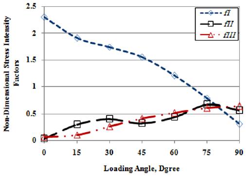
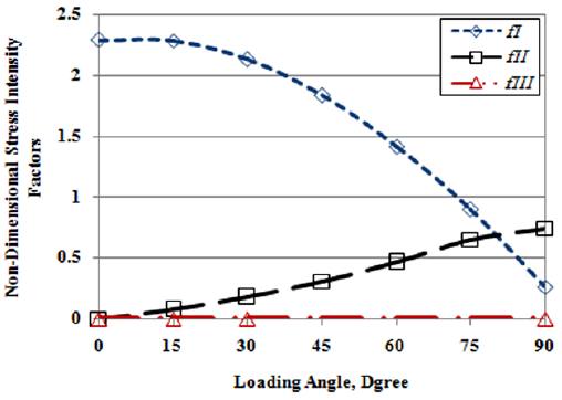
From Figures 15 and 16 it can be seen that by increasing loading angle, the mode-I stress intensity factor decreases and the mode-II stress intensity factor increases for both fixtures. It also can be seen from the Figure 15 for modified Arcan device that by increasing in-plane loading angle values, mode-III non-dimensional stress intensity factors increases and for some loading angles the mode-III fracture becomes dominant. Therefore the values of fracture parameters near to mode-II loading conditions resulted from modified Arcan device are unreliable because of asymmetry of modified Arcan device. As it can be seen from the Figure 16 in new loading device the values of mode-III non-dimensional stress intensity factors are negligible in comparison with values of mode-I and mode-II non-dimensional stress intensity factors and it confirms the perfect symmetry of new loading device. By comparing the values of geometrical factors in Figures 15 and 16, it is resulted that the differences of values of mode-I and mode-II for both fixtures are about 0.5%, and 25%, respectively. Therefore it is confirmed that as the loading angle increases, the estimated errors increases in modified Arcan fixture. In order to obtain values of critical stress intensity factors, KI and KII using Equations 3, it is necessary to account non-dimensional stress intensity factors, fI (a/w) and fII (a/w). Equations 8 were fitted these parameters as loading angles varies between pure mode-I and pure mode-II for new loading device (Figure 16).

Mode-I, mode-II, and mode-III non-dimensional stress intensity factors versus various loading angles for modified Arcan device and (a/w)= 0.5.
Mode-I, mode-II, and mode-III non-dimensional stress intensity factors versus various loading angles for new loading device and (a/w)= 0.5.
5.2 Experimental Results
The experiments were conducted in three loading angles of 0°, 45° and 90° for crack length ratio of a/w= 0.5 and values of critical load were recorded according Table 1. As it can be seen from the Table 1, the fracture loads values of new fixture were more than modified Arcan fixture; it confirms that unwanted mode-III and asymmetry resulted from modified Arcan fixture causes premature fracture of specimens. An example of force-displacement curves for both fixtures according to 45 degrees mixed-mode loading is presented in Figure 17. Average critical stress intensity factors of mode-I and mode-II were calculated using Equations 3, and are summarized in Table 2. Average critical stress intensity factors of pure mode-I and pure mode-II of the new fixture and modified Arcan fixture were found as KIC = 4.43 (MPa.m 1/2) and KIC = 4.12 (MPa.m 1/2), and KIIC = 2.11 (MPa.m 1/2) and KIIC = 1.21 (MPa.m 1/2), respectively. It can be seen that critical stress intensity factor values resulted from new fixture are more than values of modified Arcan fixture in all the experiments. As it can be seen from Table 2, the differences in critical stress intensity factors were about 7.00% and 42.65% in mode-I and mode-II loading conditions, respectively. It can be resulted that the effect of asymmetry and unwanted mode-III contribution of modified Arcan fixture in mode-II is more perceptible. Therefore, it confirms that by using the new loading device, disadvantages presented in the previous mixed-mode fracture toughness test methods can be avoided and more reliable results can be achieved.
Critical mixed-mode fracture loads Pc (N) with crack length 15 mm for new and modified Arcan fixtures.
Average mixed-mode critical stress intensity factors data KC (MPa.m1/2) with crack length 15 mm for new and modified Arcan fixtures.
The calculated critical strain energy release rates GC show quantitatively how much energy must be put into the specimen to create fracture surfaces. Table 3 shows GI C , G IIC and GT C = GI C + GI IC , obtained by Equations 4 using experimental data. GIC decreases while GIIC increases with an increase in mode-II loading contribution. The opening-mode and shearing-mode critical strain energy release rates were found to be approximately 9261 J/m2 and 2101 J/m2 for new loading device, 8010 J/m2 and 690.9 J/m2 for modified Arcan device, respectively. It can be seen that GIC is larger compared to GIIC , indicating that the cracked specimen is tougher in mode-I and weaker in mode-II loading conditions. Table 3 also shows the total strain energy release rate, GTC , under various loading conditions, which decreases with the loading angle. Therefore, the results confirmed that the maximum fracture toughness occurs at mode-I loading condition. Also, it can be seen that similar to values of critical stress intensity factors, the quantities of GIC , GIIC and GTC resulted from new fixture are more than values of modified Arcan fixture in all the experiments.
Average mixed-mode critical strain energy release rates GC (J/m2) with crack length 15 mm for new and modified Arcan fixtures.
(Luna et al., 2003Luna, P., Bernal, C., Cisilino, A., Frontini, P., Cotterell, B., Mai, Y.W. (2003). The application of the essential work of fracture methodology to the plane strain fracture of ABS 3-point bend specimens, Polymer 44: 1145-1150, doi: 10.1016/S0032-3861(02)00849-2.
https://doi.org/10.1016/S0032-3861(02)00...
) investigated fracture characteristics of ABS thick 3-point bend specimens. They found that the value of the essential work at 20◦
C is in the range 3.4-4.7 kJ/m2
. The values for fracture toughness of PC/ABS blend for sample thickness of 10 mm obtained from different methods by (Lu et al., 1996Lu, M.L., Chiou, K.C., Chang, F.C. (1996). Elastic-plastic fracture toughness of PC/ABS blend based on CTOD and J-integral methods, Polymer 37: 4289-4297, doi: 10.1016/0032-3861(96)00227-3.
https://doi.org/10.1016/0032-3861(96)002...
) reported 4.10 kJ/m2
from COD method, 4.17 kJ/m2
from ASTM E813-81 method and 4.48 kJ/m2
from new J method. (Kwon and Jar, 2005Kwon, H.J., Jar, P.Y.B. (2005). Fracture toughness of polymers in shear mode, Polymer 46: 12480-12492, doi: 10.1016/j.polymer.2005.10.074.
https://doi.org/10.1016/j.polymer.2005.1...
), conducted a series of double-edge-notched Iosipescu mode I and mode II fracture tests in products made of ABS. Value of fracture toughness for mode II fracture of ABS was found to be around 32.3 kJ/m2
that was about 2.5 times of the value for mode I fracture of 13.1 kJ/m2
. In the present study, the mixed-mode fracture behaviour for ABS polymeric material specimens was investigated based on experimental and numerical analyses using new loading device and modified Arcan test methods. The opening-mode and shearing-mode critical strain energy release rates for sample thickness of 10 mm resulted from new loading device were found to be approximately 9.3 kJ/m2
and 2.1 kJ/m2
, respectively. Both mode-I and mode-II fracture toughness for the new test methodology specimen were found more than those for 3-point bend and double-edge-notched Iosipescu specimens. The reason for these differences in fracture toughness may be related to the mode of crack growth and the analysis and test methodology. Although further work is required to obtain accurate information on evaluation of fracture toughness of ABS polymeric material under mixed mode loading conditions, the higher value of mode-I and mode-II fracture toughness can be obtained from the new test methodology specimen rather than 3-point bend and double-edge-notched Iosipescu specimens.
6 CONCLUSION AND SUMMARY
A broad experimental and analytical efforts using fracture mechanics was conducted to investigate and improve the understanding of the mixed-mode fracture behavior of materials. As a part of experimental efforts, mixed-mode fracture tests were performed using modified Arcan and new loading fixtures under mode-I, mixed-mode and mode-II loading conditions. In this work, a new loading device and specimen were made for the mixed-mode fracture test, which allows mode-I, mode-II, and almost any combination of mode-I and mode-II loading to be crated and tested with the same test specimen configuration. It is a simple test procedure, clamping/unclamping the specimens is easy to achieve and only one type of specimen is required to generate all loading conditions and disadvantages presented in the previous mixed-mode fracture toughness test methods can be avoided. The new fixture has perfect symmetry which provides a uniform stress state, creates the pure plane strain conditions and eliminates the unwanted mode-III of modified Arcan fixture.
In this study, in order to compare the fracture parameters resulted from new fixture and modified Arcan fixture, the mixed-mode fracture behavior of ABS polymeric material was investigated. By studying the numerical and experimental fracture results of ABS polymer specimens, average critical stress intensity factors of pure mode-I and pure mode-II of the new fixture and modified Arcan fixture were found KIC = 4.43 (MPa.m 1/2) and KIC = 4.12 (MPa.m 1/2), and KIIC = 2.11 (MPa.m 1/2) and KIIC = 1.21 (MPa.m 1/2), respectively. The values of critical stress intensity factors resulted from new fixture were more than values of modified Arcan fixture in all the experiments. The differences of critical stress intensity factors were about 7.00% and 42.65% in mode-I and mode-II loading conditions, respectively. It is resulted that by increasing in-plane loading angle values of mode-III non-dimensional stress intensity factors increase for modified Arcan device. Therefore the values of fracture parameters near to mode-II loading conditions resulted from modified Arcan device are unreliable. According to the results, the asymmetry and unwanted mode-III of modified Arcan fixture had an important role on fracture results especially close to the pure mode-II loading angles.
REFERENCES
- ABAQUS V 6.7. (2007). User's Manual. Dassault Systemes Simulia Corp., Providence, Rhode Island.
- Anderson, T.L. (2005). Fracture mechanics fundamentals and applications, third ed. CRC Press, Texas.
- Arcan, M., Hashin, Z., Voloshin, A. (1978). A Method to Produce Uniform Plane-stress States with Applications to Fiber-reinforced Materials, Experimental Mechanics 18: 141-146, doi:10.1007/BF02324146.
» https://doi.org/10.1007/BF02324146 - Ayatollahi, M.R., Sedighiani, K. (2012). A T-stress controlled specimen for mixed mode fracture experiments on brittle materials, European Journal of Mechanics -A/Solids 36: 83-93, doi:10.1016/j.euromechsol.2012.02.008.
» https://doi.org/10.1016/j.euromechsol.2012.02.008 - Ban, H., Im, S., Kim, Y. (2015). Mixed-mode fracture characterization of fine aggregate mixtures using semicircular bend fracture test and extended finite element modeling, Construction and Building Materials 101: 721-729, doi: 10.1016/j.conbuildmat.2015.10.083.
» https://doi.org/10.1016/j.conbuildmat.2015.10.083 - Becht, G., Jr, W. G. (1988). Design and analysis of the crack rail shear specimen for mode III interlaminar fracture, Composites Science and Techology 31: 143-157, doi:10.1016/0266-3538(88)90088-7.
» https://doi.org/10.1016/0266-3538(88)90088-7 - Ben Salem, N., Jumel, J., Budzik, M.K., Shanahan, M.E.R., Lavelle, F. (2014). Analytical and experimental investigations of crack propagation in adhesively bonded joints with the Mixed Mode Bending (MMB) test Part I: Macroscopic analysis & Digital Image Correlation measurements, Theoretical and Applied Fracture Mechanics 74: 209-221, doi:10.1016/j.tafmec.2014.05.006.
» https://doi.org/10.1016/j.tafmec.2014.05.006 - Choupani, M., Ayatollahi, M. R., Mallakzadeh, M. (2015). Investigation of Fracture in an Interface Crack Between Bone Cement and Stainless Steel, Latin American Journal of Solids and Structures 12: 446-460, doi: 10.1590/1679-78251142.
» https://doi.org/10.1590/1679-78251142 - Cognard, J.Y., Créac'hcadec, R.C., Sohier, L., Davies, P. (2008). Analysis of the nonlinear behavior of adhesives in bonded assemblies-Comparison of TAST and Arcan tests, International Journal of Adhesion and Adhesives 28: 393-404, doi:10.1016/j.ijadhadh.2008.04.006.
» https://doi.org/10.1016/j.ijadhadh.2008.04.006 - Cognard, J.Y., Sohier, L., Davies, P. (2011). A modified Arcan test to analyze the behavior of composites and their assemblies under out-of-plane loadings, Composites Part A: Applied Science and Manufacturing 42: 111-121, doi:10.1016/j.compositesa.2010.10.012.
» https://doi.org/10.1016/j.compositesa.2010.10.012 - Davidson, P., Waas, A.M., Yerramalli, C.S. (2012). Experimental determination of validated, critical interfacial modes I and II energy release rates in a composite sandwich panel, Composite Structures 94: 477-483, doi:10.1016/j.compstruct.2011.08.007.
» https://doi.org/10.1016/j.compstruct.2011.08.007 - Dharmawan, F., Simpson, G., Herszberg, I., John, S. (2006). Mixed mode fracture toughness of GFRP composites, Composite Structures 75: 328-338, doi:10.1016/j.compstruct.2006.04.020.
» https://doi.org/10.1016/j.compstruct.2006.04.020 - Es'hagi Oskui, A., Choupani, N., Haddadi, E. (2013). Experimental & Numerical Investigation of Fracture of ABS Polymeric Material for Different Sample's Thickness Using a New Loading Device, Polymer Engineering & Science 54: 2086-2096, doi:10.1002/pen.23745.
» https://doi.org/10.1002/pen.23745 - Gdoutos, E.E. (2005). Fracture Mechanics, second ed. Springer, Greece.
- Greer Jr, J.M., Galyon Dorman, S.E., Hammond, M.J. (2011). Some comments on the Arcan mixed-mode (I/II) test specimen, Engineering Fracture Mechanics 78: 2088-2094, doi:10.1016/j.engfracmech.2011.03.017.
» https://doi.org/10.1016/j.engfracmech.2011.03.017 - Heydari, M.H., Choupani, N., Shameli, M. (2011). Experimental and Numerical Investigation of Mixed-Mode Interlaminar Fracture of Carbon-Polyester Laminated Woven Composite by Using Arcan Set-up, Applied Composite Materials 18: 499-511, doi:10.1007/s10443-011-9223-x.
» https://doi.org/10.1007/s10443-011-9223-x - Hosseini, S.R., Choupani, N., Gharabaghi, A.R.M. (2008). Experimental Estimation of Mixed-Mode Fracture Properties of Steel Weld, International Journal of Civil, Environmental, Structural, Construction and Architectural Engineering 2: 86-91.
- Kwon, H.J., Jar, P.Y.B. (2005). Fracture toughness of polymers in shear mode, Polymer 46: 12480-12492, doi: 10.1016/j.polymer.2005.10.074.
» https://doi.org/10.1016/j.polymer.2005.10.074 - Lu, M.L., Chiou, K.C., Chang, F.C. (1996). Elastic-plastic fracture toughness of PC/ABS blend based on CTOD and J-integral methods, Polymer 37: 4289-4297, doi: 10.1016/0032-3861(96)00227-3.
» https://doi.org/10.1016/0032-3861(96)00227-3 - Luna, P., Bernal, C., Cisilino, A., Frontini, P., Cotterell, B., Mai, Y.W. (2003). The application of the essential work of fracture methodology to the plane strain fracture of ABS 3-point bend specimens, Polymer 44: 1145-1150, doi: 10.1016/S0032-3861(02)00849-2.
» https://doi.org/10.1016/S0032-3861(02)00849-2 - Nikbakht, M., Choupani, N. (2009). Experimental investigation of mixed-mode fracture behavior of woven laminated composite, Journal of Materials Science 44: 3428-3437, doi:10.1007/s10853-009-3456-1.
» https://doi.org/10.1007/s10853-009-3456-1 - Nunes, L.C.S., Reis, J.M.L. (2014). Experimental investigation of mixed-mode-I/II fracture in polymer mortars using digital image correlation method, Latin American Journal of Solids and Structures 11: 330-343.
- Pucillo, G.P., Grasso, M., Penta, F., Pinto, P. (2011). On the mechanical characterization of materials by Arcan-type specimens, Engineering Fracture Mechanics 78: 1729-1741, doi:10.1016/j.engfracmech.2011.02.002.
» https://doi.org/10.1016/j.engfracmech.2011.02.002 - Reeder, J.R. (1990). 3D Mixed-Mode Delamination Fracture Criteria-An Experimentalist's Perspective, NASA Langley Research Center, M/S 188E, Hampton, VA 23681-2199, USA. http://ntrs.nasa.gov/archive/nasa/casi.ntrs.nasa.gov/20060048260.pdf
» http://ntrs.nasa.gov/archive/nasa/casi.ntrs.nasa.gov/20060048260.pdf - Reeder, J.R., Crews, J.R. (1990). Mixed-Mode Bending Method for Delamination Testing, AIAA J. 28, 1270-1276.
- Shokrieh, M.M., Heidari-Rarani, M. (2011). Effect of stacking sequence on R-curve behavior of glass/epoxy DCB laminates with 0°//0° crack interface, Materials Science and Engineering 529: 265-269, doi:10.1016/j.msea.2011.09.027.
» https://doi.org/10.1016/j.msea.2011.09.027 - Sih, G.C., Theocaris, P.S. (1981). Mixed mode crack propagation, Proceedings of the First USA-Greece Symposium on Mixed Mode Crack Propagation: held at the Athens National Technical University, Athens, Greece, ISBN 9028626913, http://trove.nla.gov.au/version/30825171
» http://trove.nla.gov.au/version/30825171 - Silva, F.G.A., de Moura, M.F.S.F., Dourado, N., Xavier, J., Pereira, F.A.M., Morais, J.J.L., Dias, M.I.R. (2016). Mixed-mode I+II fracture characterization of human cortical bone using the Single Leg Bending test, Journal of the Mechanical Behavior of Biomedical Materials 54: 72-81, doi: 10.1016/j.jmbbm.2015.09.004.
» https://doi.org/10.1016/j.jmbbm.2015.09.004 - Song, J.H., Huh, H. (2011). Failure characterization of spot welds under combined axial-shear loading conditions, International Journal of Mechanical Sciences 53: 513-525, doi:10.1016/j.ijmecsci.2011.04.008.
» https://doi.org/10.1016/j.ijmecsci.2011.04.008 - Verma, S.K., Kumar, P., Kishore, N.N. (1995), Evaluation of critical interlaminar sif of DCB specimen made of slender cantilever, Engineering Fracture Mechanics 50: 345-353, doi:10.1016/0013-7944(94)00204-U.
» https://doi.org/10.1016/0013-7944(94)00204-U - Zacharopoulos, D.A. (2004). Stability analysis of crack path using the strain energy density theory, Theoretical and Applied Fracture Mechanics 41: 327-337, doi:10.1016/j.tafmec.2003.11.018.
» https://doi.org/10.1016/j.tafmec.2003.11.018
Publication Dates
-
Publication in this collection
Aug 2016
History
-
Received
09 Jan 2016 -
Reviewed
16 Mar 2016 -
Accepted
20 Mar 2016