Abstract
This paper presents effects of shear deformation on flutter instability of cantilever beam subject to a concentrated follower force. The discrete form of equation of motion is formulated based on the Lagrange. In the presented formulation, the beam is modeled using Timoshenko beam theory, and constant shear distribution through the thickness of the beam is considered. Consistent interpolation scheme is adopted to avoid the shear locking for thin beams. Consequently, convergence of the finite element simulation is enhanced. The effect of rotary inertial term is considered in the flutter study, which has significant influence on the beam behavior as the beam thickness increases. The axial degrees of freedom are taken into account in energy expressions, to improve the accuracy of the results. Results presented for different beam geometries. The numerical results show high efficiency and good convergence characteristic. The effect of concentrated mass on the flutter instability of beam is considered and results are presented for various locations and values of concentrated masses. Furthermore, the shear effects are highlighted in this study by comparing the results obtained from the Euler-Bernoulli with those obtained from the Timoshenko beam model.
Keywords:
Follower Force; Flutter Instability; Non-conservative Force; Timoshenko Theory; Cantilever Beam; Finite Element Method
1 INTRODUCTION
Stability of the system under applied non-conservative force has been considered through the work of many scientists. A typical problem for this kind is a cantilever beam subjected to a tip concentrated follower force, known as Beck's column. The beam considered in this paper is under the action of an axial follower force, which its direction remains tangential to the deformed axis of the beam. Forces are conservative if their components are the negative derivatives of a scalar potential function, and dependent of spatial coordinate only, such as gravitational force, which is a well-known sample of conservative forces. In some cases, such as those studied in this paper, some parameters of force acting on the system are a function of system parameters. In this case, the force is dependent on the system parameters and is no longer conservative. The clamped beam under the action of tip follower force is known as the mathematical model for special aerospace structures (Sugiyama, 1999Y. Sugiyama, M. A. Langthjem, B.-J. Ryu, (1999), Realistic Follower Forces, Journal of Sound and Vibration, Vol. 225 (4), pp. 779-782 and Mallik et al. 2005A. K. Mallik, J. K. Bhattacharjee, (2005), Stability Problems in Applied Mechanics, Alpha Science International Ltd. Oxford, U.K.). In addition, as a suitable model for investigating behaviors of pipes conveying fluid has been considered by many researchers. With some modification, this model is applicable to the vibration problems of automotive disk and drum-brake systems that involve dry friction (Mottershead et al., 1997Mottershead, J. E., Ouyang, H., Cartemell, M. P., and Friswell, M. I., (1997), Parametric Resonances in an Annular Disc, With a Rotating System of Distributed Mass and Elasticity, and the Effects of Friction and Damping, Proc. R. Soc. London, Ser. A, 453, pp. 1-19. and 1995Mottershead, J. E. and S. N. CHAN (1995), Flutter instability of circular discs with frictional follower loads. Transactions of the ASME, Journal of Vibration and Acoustics 117, 161-163.). For systems consisting of non-conservative forces, exact solutions (Beck, 1952Beck, M., (1952), Die Knicklast des einseitigeingespannten tangential gedruckten Stabes, ZAMP 3, 225-228. and Bolotin, V. V. 1965Bolotin, V. V. (1965). Nonconservative Problems of the Theory of Elastic Stability.Pergamon Press, London.) are complicated or do not exist. Therefore, stability analysis regarding these systems is mostly based on approximate techniques, such as finite element method, Galerkin method, etc. Extensive survey of the problem involving non-conservative forces is presented in Elishakoff (2005Isaac Elishakoff., (2005), Controversy Associated With the So-Called ''Follower Forces'': Critical Overview, Applied Mechanics Reviews, Vol. 58, Issue 2, pp. 59-70.) and Langthjem et al. (2000)M. A. Langthjem, Y. Sugiyama, (2000), Dynamic Stability Of Columns Subjected To Follower Loads: A Survey, Journal of Sound and Vibration, Vol. 238, No. 5, pp. 809-851. where the history of analysis and controversies about the Beck's column are presented in a comprehensive manner. The dynamic analysis of cantilever beam under follower force and intermediate spring support is investigated by Lee (1995)H. P. Lee, (1995), Divergence and Flutter of a Cantilever Rod with an Intermediate Spring Support, Int. J. Solids Structures Vol. 32, No. 10, pp. 1371-1382. based on the Lagrange approach solved using the assumed modes. In his paper, Lee employed the Euler beam theory. The applied mode shapes are the same as vibration mode shapes of a cantilever beam, obtained from solution of associated differential equation along with boundary conditions (Clough and Penzien, 1975RayW. Clough, Joseph Penzien, (1975), Dynamics of Structures, McGraw-Hill.). He also extended the method to the tapered cantilever beams on Winkler-type elastic foundation and proposed a method to take in to account the effect of viscous damping of foundation on the flutter instability of cantilever beam (Lee, 1996H. P. Lee, (1996), dynamic stability of a tapered cantilever beam on an elastic foundation subjected to a follower force,. Int. J. Solids Structures Vol. 33, No. 10. pp. 1409-1424.). There is a considerable difference between the vibration mode shapes of cantilever beam in flutter state and the natural modes of the cantilever beam. Consequently, Lee's solution shows a substantial error in the vibration analysis of beam under a follower force. The Euler beam theory, which assumes zero shear stress through the thickness of the beam, is not applicable for stubby and short beams, where transverse shear stress can severely affect the vibration behavior of beam. The Euler beam theory underestimates the deflection and overestimates the natural frequencies and buckling loads of the thick beams. As a result, in designing thick, beam like structures Timoshenko beam theory leads to a more accurate and acceptable results. Dynamic stability of Timoshenko beams are studied by Ryu and Sugiyama (1994)B. J. Ryu, Y. Sugiyama, (1994), Dynamic Stability of Cantilevered Timoshenko Columns Subjected to a Rocket Thrust, Computers and Structures Vol. 51. No. 4, pp. 331-335.. They also studied the effect of concentrated tip mass on the stability of beams under follower force. Moreover, for investigation of the effects of shear deformation, they introduced a factor that contains parameters such as shear correction factor. The formulations are defined by the out of plane deflection only and axial degrees of freedoms are neglected. Ignoring these degrees of freedom cause errors in predictions of thick beams behavior and neglects the effect of axial modes. By extending the method, Ryu et al. (1998)Bong Jo Ryua, Kazuo Katayamab, Yoshihiko Sugiyamac, (1998), Dynamic stability of Timoshenko columns subjected to subtangential forces, Computers and Structures 68 499-512. studied dynamic stability of a vertical cantilever beam under sub-tangential follower force. In their study, the Follower force is assumed to be summation of a follower force and a dead load from a rigid body on the end of a vertical column. They used finite element method and presented results for different geometries and conditions of beam.
Kim and et al. (2000Kim, K.H. and Kim, J.H., (2000), Effect of Crack on the Dynamic Stability of a Free-Free Beam Subjected to a Follower Force, Journal of Sound and Vibration, Vol. 233, No.1, 119-135.) investigated the effect of crack on the dynamic stability of a Free-Free beam subjected to a follower force. Wang (2004)Q. Wang, (2004), A comprehensive stability analysis of a cracked beam subjected to follower compression, International Journal of Solids and Structures 41 4875-4888. studied the effect of the crack intensity and location on the buckling or flutter compressive load of a beam with a single crack. Viola et al. (2007)E. Viola, P. Ricci, M.H. Aliabadi, (2007), Free vibration analysis of axially loaded cracked Timoshenko beam structures using the dynamic stiffness method, Journal of Sound and Vibration 304, 124-153. considered the effect of sub- tangential forces on the dynamic stability of a cracked beam. Caddemi et al. (2014)Caddemi, S., I. Caliò, and F. Cannizzaro, (2014), Flutter and divergence instability of the multi-cracked cantilever beam-column, Journal of Sound and Vibration 333.6, 1718-1733. investigated the stability of multi-cracked cantilever Euler beam-column subjected to conservative or nonconservative axial loads.
In this paper, the finite element method in context of Timoshenko beam theory is used to predict dynamic instability behavior of cantilever beam subjected to an end follower force. In current studies, non-linear strain terms are used to derive a geometric stiffness matrix, taking in to account the axial degrees of freedom effects. The linear interpolation functions are adopted for the axial displacements and rotation terms, while the quadratic interpolation functions are employed as trial functions for out of plane deflection of the beam. As a result, a consistent interpolation scheme is achieved for the transverse shear strains, and the shear locking for thin beams is avoided and convergence of the analysis is enhanced. Details of the present method are described in the following sections and the components of finite element procedure are discussed in detail. As stated, Beck's column is considered mostly for analysis of hollow shape structures such as pipes, etc. In the case of complicated cross sections, the shear correction factor and other cross sectional parameters are crucial to achieve the accurate analysis. These effects are investigated in the present study. In some of the applications, Beck's column model is applied for analyzing the structures with variable mass and changes in location of mass center. For modeling such structures, it is possible to assume a concentrated mass on a beam where location and magnitudes of mass changes. The results for flutter instability of beams with concentrated masses are presented and a parameter study on the mass value and its location is performed. The results of dynamic analysis are also compared for various beam slenderness ratios.
2 THE BEAM CONSTITUTIVE RELATIONS
The Timoshenko beam theory (TBT) presented in this paper is based on the same assumptions as those of the Euler beam theory, except that it no longer assumes that the straight planes normal to the neutral axis remain normal after deformation. Instead, it assumes the normal plane rotates with respect to normal to the neutral axis before deformation as shown in Figure 1.
Cross Section of Beam in TBT; (a) before deformation; (b) after deformation (C. M. Wang, et. al, 2000C. M. Wang, J. N. Reddy; K.H. Lee., (2000), Shear Deformation Theories of Beams and Plates. Relationships with Classical Solution. Elsevier, U.K.).
The displacement fields for the TBT (u; w) in Cartesian coordinates (x; z) where behavior of the beam after deformation is defined can be expressed as follows (C. M. Wang, et. al, 2000C. M. Wang, J. N. Reddy; K.H. Lee., (2000), Shear Deformation Theories of Beams and Plates. Relationships with Classical Solution. Elsevier, U.K.):
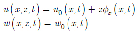
where u 0, w 0 and ϕx are the unknown functions which define the displacement relations of Timoshenko beam. It is possible to convert this equation into the Euler beam theory by a simple substitution. The condition ϕx = - w ,x in equation (1), yields the same displacement field as that of the Euler beam theory (EBT). The variational functional of the above displacement field requires the satisfaction of C 0 continuity of variables. The degree of continuity for parameters must be considered in choosing interpolation function for each unknown function in finite element formulation.
Employing the linear strain-displacement relationships of three-dimensional elasticity theory in conjunction with equation (1), the five strain components of TBT at a general point can be expressed in terms of the fundamental neutral axis quantities. Thus, the in-plane direct and shear strains of TBT are defined as follows:
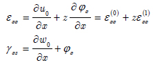
From the equation (2) where the strains of beam are defined, it can be noticed that normal strain of the beam is a linear function of vertical displacement coordinate Z (same as Euler beam, theory) and the shear strain is defined as a constant value. The shear strain of the beam from the elasticity and equilibrium equation of beam is obtained as a quadratic function of the vertical displacement. To compensate the error caused by assuming the constant variation of shear strain through the thickness, shear correction factor is used in this analysis.
The constitutive equations for the beam, the geometry is shown in Figure 1, can be obtained through the use of equation (2), Hook's law and appropriate integration through the thickness of the beam. The constitutive equation which defines the relation between the stress and strain of the beam in a matrix form is expressed as:
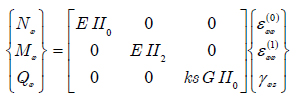
Or

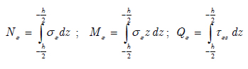
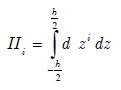
where Mx, Nx and Qx are the stress resultants of the beam which is defined by integration through the thickness of beam in equation (5) and II i is described in equation (6):
Parameters for inertia moments of cross section which appeared in the constitutive equation of the beam are defined as below:
In the above equation, d is the width of beam which is a specific height and defined as a function of vertical coordinate (z).
Shear correction factor, ks, also appeared in the constitutive equation. The calculated shear strain through thickness of the beam by using equilibrium stresses, assumes parabolic distribution of stress through the thickness. In contrast, the Timoshenko beam theory assumes the constant state of shear stress through the beam height. To take into account the difference of energy due to shear, which is predicted by either of these theories, the ks shear correction factor is introduced (C. M. Wang, et. al, 2000C. M. Wang, J. N. Reddy; K.H. Lee., (2000), Shear Deformation Theories of Beams and Plates. Relationships with Classical Solution. Elsevier, U.K.). This factor is defined using to material and geometry of the beam. For beams with rectangular and circular cross sections and isotropic material, it is assumed 5/6 and 9/10, respectively. Detailed formulation for shear correction factor of shallow circular beams will be described later in this paper. In constitutive equation of beam, E is the Young module of elasticity and G is termed as shear module. Visual descriptions of parameters defining the geometry of the beam are given in Figure 2. For small deformations of beam, the angle between the deformed and un-deformed neutral axis of the beam configuration at the end is assumed to be identical to the rotation φx.
3 ENERGY EXPRESSION OF A BEAM ELEMENT
The extended Hamilton's principle for small motions of the beam under tip follower force is expressed as follows:
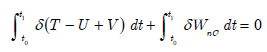
In the above equation, U is the strain energy of the beam element, T is the kinetic energy for vibration motion of the beam, Vis the loss in potential energy or the potential energy due to conservative component of follower force, and Wnc is the virtual work, which resulted from the non-conservative component of tip follower force. The strain energy of a beam element is defined with respect to the material properties of the beam and the strain vectors as follows:
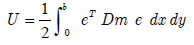
e and Dm are the strain vector and material matrix of the element respectively. On substituting Equations (2) to (3) and then into Eq.(8), it is possible to obtain the strain energy of an element as a function of unknown displacement functions:

The kinetic energy of beam in this study is defined as a summation of the kinetic energy due to vibration of the whole beam and the movements of concentrated mass, CM , which is placed in a different arbitrary location of beam as shown in Figure 2. The kinetic energy of a vibrating beam is defined as:
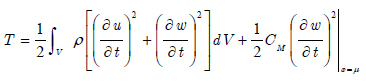
In the above equation, ρ, is the material density of a beam which is assumed to be constant in the beam's length. Using equation (1) and integrating through the thickness of the beam, the kinetic energy of beam element is defined as:
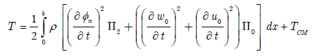
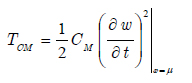
In equation above TCM is dealing with kinetic energy due to the concentrated mass, which can be a mathematical model for heavy machinery or any abrupt change in the density of beam. This energy is neglected in all elements except one, which contains the concentrated mass. For this element, the expression below is added to the kinetic energy of the beam element:
In the present formulation and in order to obtain the characteristic matrices, follower force on the beam is divided into two separate components; one with constant magnitude whose direction always remains parallel to the neutral axis of the un-deformed beam. This component is conservative and the potential energy due to this conservative force is defined as:
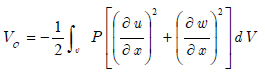
By importing the displacement functions of TBT from equation (1) into the equation above the potential energy VC is expressed as:
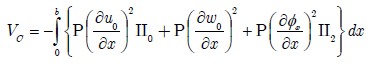
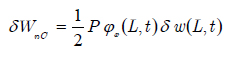
It is clear that in this formulation the non-destabilizing effect corresponding to rotational degrees of freedom is considered in the loss potential energy for the beam. The direction of the second component is normal to the neutral axis of an un-deformed beam and its magnitude changes corresponding to rotation of the normal line. This component of force is a function of the degrees of freedom of the beam. Thus, it is non-conservative and no potential energy is defined for it. Indeed, the virtual work done by this transverse component can be attained. For small deflections of beam, the vertical component of follower force is defined as a product of its magnitude and the rotation of beam at the end. Finally, the virtual force is defined by equation below, which is function of degrees of freedom at the point on which the load is imposed.
4 THE FINITE ELEMENT FORMULATION OF THE PROBLEM
The unknown parameters in equation (1) are defined as a time dependent function. It is assumed that the unknown degrees of freedoms are combined from the time dependent function and displacement degrees of freedom as the following equation:

Considering the above equation, variation of each of the displacement functions is represented spatially as a product of Lagrangian polynomial and degrees of freedom vector.
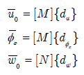
where:
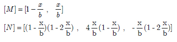
M and N are linear and quadratic Lagrange polynomials, respectively. Visual description of these functions is shown in Figure 3. Consequently, for the purpose of interpolation, two nodes are needed for linear shape function and three nodes for quadratic function. As a result, the beam elements will have three node and seven degrees of freedom each.
The description of current beam element and the system of degrees of freedom is shown in Figure 4. There are two nodes and four degrees of freedom for φx and u0 but, w0 is interpolated using three nodes and 3 degrees of freedom in the element.
In Figure 4, b corresponds to the length of an element and described as:

where, ne is the number of elements for the beam analysis. Approximation for unknown functions in equation (18) causes φx and w,x to be the polynomials from the same degree. Consequently, the consistent interpolation (N. Reddy, 2006N. Reddy. (2006), An Introduction to the Finite Element Method.Third Edition. McGraw-Hill, NY.) is applied in the present study. As a result, shear locking is avoided and convergence of method is enhanced, especially for the analysis of thin beams.
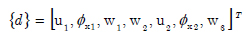
By substituting the element displacement fields given in equation (17) into equations (8)-(15), expressions can be derived for the strain energy, kinetic energy, potential energy of the applied load, and also virtual work of the non-conservative component of follower force. These expressions are quadratic functions of the complete set of displacement degrees of freedom of each element. For each element, the column matrix of {d} for total degrees of freedom of beam element is defined as below:
Finally, the expressions for energy and work will be written as the familiar forms of:

In the present study, these expressions are obtained using differentiation with respect to each degree of freedom. The matrices are containing polynomials as their elements. Thus, it is possible to carry out integrations involved in evaluating the matrices exactly over the length of the element, which makes the solution of the problem faster. In addition, it is possible to use methods such as gauss integration in finite element formulation.
Obtaining natural frequencies of structures generally with respect to imposed end force requires one to solve an eigenvalue problem as follows:
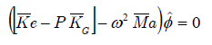
where  and
and  are the elastic stiffness matrix, geometric stiffness matrix and mass consistent matrix of the whole beam structure respectively.
  ,
,  is the corresponding eigenvector and
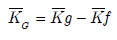
In the present study,  is a nonsymmetrical matrix due to non-conservative force and is defined as a combination of a symmetric geometric matrix (due to conservative component of follower force) and the non-symmetric matrix according to its non-conservative component as below:
These stiffness matrices can be assembled in the standard fashion by defining a simple connectivity matrix (N. Reddy, 2006). Equation (23) is solved using an appropriate eigenvalue solution procedure that will give the beam's natural vibration mode shapes and frequencies at the applied follower force (Bathe, K. J. 1982Bathe, K. J. (1982), Finite Element Procedures in Engineering Analysis. Prentice-Hall, New Jersey,).
5 NUMERICAL STUDY
Ryu et al. (1994)B. J. Ryu, Y. Sugiyama, (1994), Dynamic Stability of Cantilevered Timoshenko Columns Subjected to a Rocket Thrust, Computers and Structures Vol. 51. No. 4, pp. 331-335. investigated the effect of shear deformation on flutter stability of the beam through introducing the shear deformation parameters which are defined as a function of beam geometry as below:
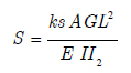
To validate the obtained result from the current method they are compared with those of Ryu et al. (1994)B. J. Ryu, Y. Sugiyama, (1994), Dynamic Stability of Cantilevered Timoshenko Columns Subjected to a Rocket Thrust, Computers and Structures Vol. 51. No. 4, pp. 331-335., for different values of shear deformation parameters and the results are shown in Table 1. The results are obtained for rectangular cross section with k s=5/6 for different shear deformation factors and corresponding slenderness ratios.
It should be noted that in a comparison between results there exists a small difference in the results from the present method and those reported in Ryu et al. (1994)B. J. Ryu, Y. Sugiyama, (1994), Dynamic Stability of Cantilevered Timoshenko Columns Subjected to a Rocket Thrust, Computers and Structures Vol. 51. No. 4, pp. 331-335.. Destabilizing effect of shear degrees of freedom (equations (13)-(14)) was not considered in Ryu et al. (1994)B. J. Ryu, Y. Sugiyama, (1994), Dynamic Stability of Cantilevered Timoshenko Columns Subjected to a Rocket Thrust, Computers and Structures Vol. 51. No. 4, pp. 331-335.,and analysis was based only upon the lateral deflections. It is clear that neglecting these degrees of freedoms in geometric matrix of a beam results in a slight error of the analysis, especially for stubby beams.
The values of critical flutter load for different slenderness ratios are presented in Table 2.
Analysis is based upon both the Euler-Bernoulli and the Timoshenko beam theories. Results are compared with those reported by Lee (Lee, 1996H. P. Lee, (1996), dynamic stability of a tapered cantilever beam on an elastic foundation subjected to a follower force,. Int. J. Solids Structures Vol. 33, No. 10. pp. 1409-1424.) obtained using assumed modes method and the exact solution of differential equation of Euler-Bernoulli beam under follower force, by applying dynamic instability criteria (Beck et. al 1952Beck, M., (1952), Die Knicklast des einseitigeingespannten tangential gedruckten Stabes, ZAMP 3, 225-228., Bolotin, V. V., 1965Bolotin, V. V. (1965). Nonconservative Problems of the Theory of Elastic Stability.Pergamon Press, London.). It is worth to note that difference percentage of these result are presented in bracket in Table 2. As expected from these analysis, by increasing the beam thickness, the effect of shear deformation increases and there is more difference between the results from the Euler formulation and the present formulation, which accounts for shear deformations. As one may notice for beams with higher slenderness, the results are identical to those of Euler beam theory, as expected.
The effect of slenderness ratio on variation of natural frequencies due to follower force is shown in Figure 5 where the changes in first and second natural frequencies of cantilever beam are shown for thin and thick beams. The non dimensional parameters are defined as Pb = (PEII2)/L2 and Wb=ω(ρAL4/EII2)1/2 . By increasing the follower force to the specific value, the paths for frequency alteration due to the follower force coalesce and the beam flutter occurs.
Variation of first and second natural frequency with respect to applied follower force for different slenderness ratios.
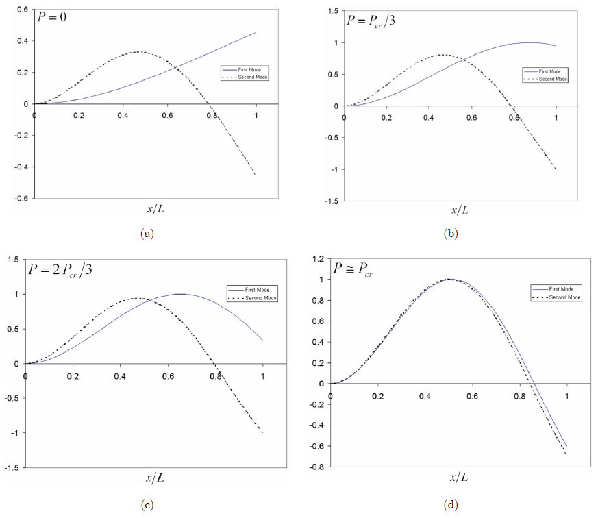
Effect of follower force on first and second mode shapes of a cantilever beam is shown in Figure 6. It is clear that by increasing the magnitude of follower force, mode shapes are merging to each other and reach or coalesce into one mode shape after critical follower force.
Mode shapes of a cantilever beam under follower force for different values of follower force.
As seen from equation (11), (kinetic energy of beam element), the presence of rotary inertia effect cause to increase the kinetic energy of system, as expected. It is clear that the natural frequencies of beam decreases with increasing of kinetic energy. Consequently, reducing natural frequencies of system causes flutter boundary is moved left, i.e., the beam flutter occurs quickly. Figure 5 and results of reference (Park, 1987Park, Y. P., (1987), Dynamic stability of a free Timoshenko beam under a controlled follower force, Journal of sound and vibration 113, 407-415.) show the correctness of the above content.
Beams with circular cross sections or pipe shape structures are more popular in various industries. As a result studying of these types of cross sections is of paramount importance in predicting behavior of pipes and aerospace structures (Curtis Petrus, 2006Ryan Curtis Petrus, (2006), Dynamics Of Fluid-Conveying Timoshenko Pipes, Ms Thesis Texas A&M University, May.).
The effect of a cross section on flutter stability is considered in Table 3, where values of a critical flutter load are presented with respect to the changes in the cross section type. Shear correction factor in circular cross section is a function of inner and outer radius of hollow beam (Cowper, 1966Cowper, G. R. (1966). The shear coefficient in Timoshenko's beam theory. Journal of applied mechanics 33.2, 335-340.):
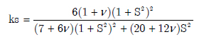
where S is the radius ratio and defined as ratio of inner Ri radius to outer radius Ro of hollow beam:

The change in the cross section leads to the variation of shear correction factor, which is defined as a function of radius and Poisson ratio in equation (25). As noted before, the effect of shear deformation effect is not negligible in analysis of thick beams. As a result, the changes in the values of critical follower force due to change in cross section (in Table 3) is more apparent for thick beams.
Effect of tip mass on flutter stability is presented in Table 4. The effect of tip force on flutter stability in the present method is compared with Ryu et al. (1994)B. J. Ryu, Y. Sugiyama, (1994), Dynamic Stability of Cantilevered Timoshenko Columns Subjected to a Rocket Thrust, Computers and Structures Vol. 51. No. 4, pp. 331-335. and a good agreement between the results is achieved. The results are presented for different values of mass ratio M*which is defined as ratio of tip mass to the mass of beam. This study is for analyzing a beam response with concentrated mass (CM ), in which xCM is equal to the length of the beam.
The effect of position of concentrated mass on natural frequencies of cantilever beam is depicted in Figure 7 where results from the present method are compared with the results from Dunkerley's approximation technique (Tse et al., 1978F. S. Tse, I. E. Morse and R. T. Hinkle, (1978), Mechanical Vibrations; Theory and Applications, Allyn and Bacon, Inc.) and good agreement can be observed. It is clear from the results that the natural frequency of a cantilever beam decreases with increase of μ.
Effect of μ on first natural frequency of cantilever beam with concentrated mass (μ=xCM/L).
Figure 8 shows the critical follower force of a cantilever beam (Flutter point) with concentrated mass for different values and location of mass. It is clear from the results that the concentrated mass on the middle of cantilever beam increases the flutter force of a beam for all shear deformation parameters. Moreover, concentrated mass on the first or last quarter of a beam has a destabilizing effect on the beam in case of flutter.
Critical follower force of cantilever beam for different values and locations of concentrated mass.
6 CONCLUSIONS
In this paper, the finite element method is applied to flutter analysis of a cantilever Timoshenko beam under non-conservative follower force. The effect of shear deformation and rotational kinetic energy are taken into account. Results are compared with those reported elsewhere, and comparison among the results is presented. The effect of concentrated mass on flutter instability of cantilever mass is inspected and has been shown that the concentrated mass increases or decreases the critical flutter force of beam depending to its location on the beam. The effect of axial and rotational degrees of freedom inertias in Timoshenko beam is considered in the present study. It is concluded from the results that including the inertia of these degrees of freedom causes a changes in the result for critical follower force. In addition, it can be concluded from the obtained results that the effect of shear deformation in the critical follower force cannot be disregarded specially in the case of stubby beam cases.
Reference
- A. K. Mallik, J. K. Bhattacharjee, (2005), Stability Problems in Applied Mechanics, Alpha Science International Ltd. Oxford, U.K.
- B. J. Ryu, Y. Sugiyama, (1994), Dynamic Stability of Cantilevered Timoshenko Columns Subjected to a Rocket Thrust, Computers and Structures Vol. 51. No. 4, pp. 331-335.
- Bathe, K. J. (1982), Finite Element Procedures in Engineering Analysis. Prentice-Hall, New Jersey,
- Beck, M., (1952), Die Knicklast des einseitigeingespannten tangential gedruckten Stabes, ZAMP 3, 225-228.
- Bolotin, V. V. (1965). Nonconservative Problems of the Theory of Elastic Stability.Pergamon Press, London.
- Bong Jo Ryua, Kazuo Katayamab, Yoshihiko Sugiyamac, (1998), Dynamic stability of Timoshenko columns subjected to subtangential forces, Computers and Structures 68 499-512.
- C. M. Wang, J. N. Reddy; K.H. Lee., (2000), Shear Deformation Theories of Beams and Plates. Relationships with Classical Solution. Elsevier, U.K.
- Caddemi, S., I. Caliò, and F. Cannizzaro, (2014), Flutter and divergence instability of the multi-cracked cantilever beam-column, Journal of Sound and Vibration 333.6, 1718-1733.
- Cowper, G. R. (1966). The shear coefficient in Timoshenko's beam theory. Journal of applied mechanics 33.2, 335-340.
- E. Viola, P. Ricci, M.H. Aliabadi, (2007), Free vibration analysis of axially loaded cracked Timoshenko beam structures using the dynamic stiffness method, Journal of Sound and Vibration 304, 124-153.
- F. S. Tse, I. E. Morse and R. T. Hinkle, (1978), Mechanical Vibrations; Theory and Applications, Allyn and Bacon, Inc.
- H. P. Lee, (1995), Divergence and Flutter of a Cantilever Rod with an Intermediate Spring Support, Int. J. Solids Structures Vol. 32, No. 10, pp. 1371-1382.
- H. P. Lee, (1996), dynamic stability of a tapered cantilever beam on an elastic foundation subjected to a follower force,. Int. J. Solids Structures Vol. 33, No. 10. pp. 1409-1424.
- Isaac Elishakoff., (2005), Controversy Associated With the So-Called ''Follower Forces'': Critical Overview, Applied Mechanics Reviews, Vol. 58, Issue 2, pp. 59-70.
- Kim, K.H. and Kim, J.H., (2000), Effect of Crack on the Dynamic Stability of a Free-Free Beam Subjected to a Follower Force, Journal of Sound and Vibration, Vol. 233, No.1, 119-135.
- M. A. Langthjem, Y. Sugiyama, (2000), Dynamic Stability Of Columns Subjected To Follower Loads: A Survey, Journal of Sound and Vibration, Vol. 238, No. 5, pp. 809-851.
- Mottershead, J. E. and S. N. CHAN (1995), Flutter instability of circular discs with frictional follower loads. Transactions of the ASME, Journal of Vibration and Acoustics 117, 161-163.
- Mottershead, J. E., Ouyang, H., Cartemell, M. P., and Friswell, M. I., (1997), Parametric Resonances in an Annular Disc, With a Rotating System of Distributed Mass and Elasticity, and the Effects of Friction and Damping, Proc. R. Soc. London, Ser. A, 453, pp. 1-19.
- N. Reddy. (2006), An Introduction to the Finite Element Method.Third Edition. McGraw-Hill, NY.
- Park, Y. P., (1987), Dynamic stability of a free Timoshenko beam under a controlled follower force, Journal of sound and vibration 113, 407-415.
- Q. Wang, (2004), A comprehensive stability analysis of a cracked beam subjected to follower compression, International Journal of Solids and Structures 41 4875-4888.
- RayW. Clough, Joseph Penzien, (1975), Dynamics of Structures, McGraw-Hill.
- Ryan Curtis Petrus, (2006), Dynamics Of Fluid-Conveying Timoshenko Pipes, Ms Thesis Texas A&M University, May.
- Y. Sugiyama, M. A. Langthjem, B.-J. Ryu, (1999), Realistic Follower Forces, Journal of Sound and Vibration, Vol. 225 (4), pp. 779-782
Publication Dates
-
Publication in this collection
Dec 2016
History
-
Received
29 Mar 2016 -
Reviewed
23 Sept 2016 -
Accepted
04 Oct 2016