Abstract
This study compares ball, bar-clip and bar-ball attachment systems for implant-retained mandibular overdentures with three implants. The first implant is placed in the middle of the mandible and the other two are imbedded in the first premolar regions. Linear elastic finite element analysis is used for design analysis. Three dimensional geometry of the mandible is generated from computed tomography. Other parts are modeled using SolidWorks software. The foodstuff is positioned at the right first molar, representing the most frequent masticating situation. To obtain accurate mesh-independent results, finite element models are solved using several mesh grids. They are then validated by means of a detailed convergence analysis. The results demonstrate that the highest von-Mises stress in the bone is always located around the neck of the implant, at its upper threads. Ball and bar-ball attachments transfer the highest and lowest stresses to the bone surrounding the implants, respectively. The lowest stresses in the cortical and cancellous bones are due to bar-ball attachment. Yet, the overdenture gets its maximum movement for this arrangement. Consequently, the use of bar-ball attachment is only recommended for the cases in which stress transferred to peri-implant bone is more important than overdenture stability. Among the three treatment designs, ball attachment seems to exhibit the lowest lateral and overall displacements and hence, better overdenture stability.
Keywords:
Overdenture stability; cortical bone; cancellous bone; implant
1 INTRODUCTION
Currently, implant-retained overdentures have become one of the most preferred options for a complete treatment of edentulous patients (Daas et al. (2008)Daas, M., Dubois, G., Bonnet, A.S., Lipinski, P., Rignon-Bret, C., (2008). A complete finite element model of a mandibular implant-retained overdenture with two implants: Comparison between rigid and resilient attachment configuration, Medical Engineering Physics 30: 218-225. and Parkash et al. (2009)Parkash, V., D'Souza, M., Adhikari, R., (2009). A comparison of stress distribution and flexion among various designs of bar attachments for implant overdentures: a three dimensional finite element analysis, Indian Journal of Dental Research 20: 31-36.). The high success rate of this therapy is well documented by Celik and Uludag (2007)Celik, G., Uludag, B., (2007). Photoelastic stress analysis of various retention mechanisms on 3-implant-retained mandibular overdentures, The Journal Prosthetic Dentistry 97: 229-35.. Edentulous patients who use complete dentures often experience problems such as pain and insufficient stability of denture during mastication. Batenburg et al. (1998)Batenburg, R.H.K., Meijer, H.J.A., Raghoebar, G.M., Vissink, A., (1998). Treatment concept for mandibular overdentures supported by endosseous implants: a literature review, International Journal of Oral Maxillofacial Implants 13: 539-45. showed that these problems can be reduced using implant-retained overdenture. According to a work done by Grageda and Rieck (2014)Grageda, E., Rieck B., (2014). Metal-reinforced single implant mandibular overdenture retained by an attachment: A clinical report The Journal of Prosthetic Dentistry 11: 16-19., a single implant mandibular overdenture significantly increases the satisfaction an d quality of life of patients with edentulism, while the use of a metal-reinforced framework inside the acrylic resin base provides better rigidity to prevent denture fracture.
In some patients, two to four implants are used in the interforaminal region to support mandibular overdentures (Batenburg et al. (1998)Batenburg, R.H.K., Meijer, H.J.A., Raghoebar, G.M., Vissink, A., (1998). Treatment concept for mandibular overdentures supported by endosseous implants: a literature review, International Journal of Oral Maxillofacial Implants 13: 539-45.). Some of the previous works (Celik and Uludag (2007)Celik, G., Uludag, B., (2007). Photoelastic stress analysis of various retention mechanisms on 3-implant-retained mandibular overdentures, The Journal Prosthetic Dentistry 97: 229-35.; Meijer et al. (1994)Meijer, H.J.A., Starmans, F.J.M., Steen, W.H.A., Bosman, F., (1994). A three-dimensional finite element study on two versus four implants in an edentulous mandible, International Journal of Prosthodontics 7: 271-79.), have not been able to find any difference in the clinical state of patients treated either with two or four implants. However, Parkash et al. (2009)Parkash, V., D'Souza, M., Adhikari, R., (2009). A comparison of stress distribution and flexion among various designs of bar attachments for implant overdentures: a three dimensional finite element analysis, Indian Journal of Dental Research 20: 31-36. concluded that four-implant systems are better choices than two-implant systems.
Implant-retained overdentures have various attachment systems including bar-clip, ball, bar-ball, O-ring and magnet. Several studies have evaluated the effect of these attachments on implant-retained mandibular overdentures (Daas et al. (2008)Daas, M., Dubois, G., Bonnet, A.S., Lipinski, P., Rignon-Bret, C., (2008). A complete finite element model of a mandibular implant-retained overdenture with two implants: Comparison between rigid and resilient attachment configuration, Medical Engineering Physics 30: 218-225.; Parkash et al. (2009)Parkash, V., D'Souza, M., Adhikari, R., (2009). A comparison of stress distribution and flexion among various designs of bar attachments for implant overdentures: a three dimensional finite element analysis, Indian Journal of Dental Research 20: 31-36.; Celik and Uludag (2007)Celik, G., Uludag, B., (2007). Photoelastic stress analysis of various retention mechanisms on 3-implant-retained mandibular overdentures, The Journal Prosthetic Dentistry 97: 229-35.; Meijer et al. (1993)Meijer, H.J.A., Starmans, F.J.M., Steen, W.H.A., Bosman, F., (1993). A three dimensional finite element analysis of bone around dental implants in an edentulous human mandible, Archives of Oral Biology 38: 491-96. and Menicucci et al. (1998)Menicucci, G., Lorenzetti, M., Pera, P., Preti, G., (1998). Mandibular implant-retained overdenture: finite element analysis of two anchorage systems, International Journal of Oral Maxillofacial Implants 13: 369-76.). The forces resulted from mastication are transferred to implants and produce stress in peri-implant bone. These stresses must be in the certain and safe range. Very high or very low stress values can cause bone resorption and failure of treatment concept.
Long-term function of a dental implant system will depend on the biomechanical interaction between bone and the implant. Methods for evaluation of stresses around dental implant systems include photoelasticity, finite element analysis and strain measurement on the bone surface. The finite element (FE) method offers several advantages over the other methods. This includes accurate representation of complex geometries, ability of modification of the model and better representation of internal stresses and other mechanical quantities (Meijer et al. (1996)Meijer, H.J.A., Starmans, F.J.M., Steen, W.H.A., Bosman, F., (1996). Loading conditions of endosseous implants in an edentulous human mandible: a three dimensional finite element study, Journal of Oral Rehabilitation 23: 757-63.).
The influence of implant number on the biomechanical behavior of mandibular implant-retained/supported overdentures was studied by Liu et al. (2013)Liu, J., Pan, S., Dong, J., Mo, Z., Fan, Y., Feng, H., (2013). Influence of implant number on the biomechanical behavior of mandibular implant-retained/supported overdentures: A three-dimensional finite element analysis, Journal of dentistry 41: 241-9. through three-dimensional finite element analysis. The aim of this study was to evaluate strain distribution in peri-implant bone, stress in the abutments and denture stability of mandibular overdentures anchored by different numbers of implants of the same type under different loading conditions.
A survey by Dias et al. (2013)Dias, R., Moghadam, M., Kuyinu, E., Jahangiri, L., (2013). Patient satisfaction survey of mandibular two-implant-retained overdentures in a predoctoral program, The Journal of Prosthetic Dentistry 110: 76-81. on patient satisfaction with the mandibular 2-implant-retained overdenture therapy revealed that 79% of participants were satisfied with their masticatory ability, 84% were satisfied with the comfort of the prosthesis, and 89% were satisfied with the esthetics of their new prosthesis. Moreover, 85% of participants reported satisfaction with the overall treatment experience, and 90% recommended the same treatment to a friend. Similar studies were performed to examine the influence of mandibular two-implant retained overdentures on life quality of denture wearers aged between 65-82 (Geckili et al. (2011)Geckili, O., Bilhan, H., Bilgin, T., (2011). Impact of mandibular two-implant retained overdentures on life quality in a group of elderly Turkish edentulous patients, Archives of Gerontology and Geriatrics 53: 233-36.), and patient satisfaction and long-term effectiveness of tooth replacement with mandibular implant-retained overdentures (Pan et al. (2014)Pan, Y.H., Yu, L.M., Lin, T.M., (2014). Dental implant-retained mandibular overdenture therapy: A clinical study of patients' response, Journal of Dental Sciences 9: 118-24.).
A separate study by Cune et al. (2011)Cune, M., Burgers, M., van Kampen, F., de Putter, C., van der Bilt, A., (2011). Mandibular overdentures retained by two implants: 10-year results from a crossover clinical trial comparing ball-socket and bar-clip attachments, The Journal of Prosthetic Dentistry 105: 136., was performed to evaluate the patient satisfaction and clinical and prosthetic outcomes of two-implant mandibular overdenture treatment with different attachment types after 10 years of function. A similar study by Tao et al. (2012)Tao, C., Guifeng, S., Jingyu, H., Xiaoji, H., Yining, W., Yan-Fang, R., (2012). Patient satisfaction and masticatory efficiency of single implant-retained mandibular overdentures using the stud and magnetic attachments, Journal of dentistry 40: 1018- 23., on patient satisfaction and masticatory efficiency of single implant-retained mandibular overdentures was performed using the stud and magnetic attachments. Additionally, a prospective study evaluated the clinical outcome, the oral health-related quality of life, and the subjective chewing ability of patients with mandibular complete dentures retained by a single implant placed in the mandible midline (Harder et al. (2011)Harder, H., Wolfart, S., Egert, C., Kern, M., (2011). Three-year clinical outcome of single implant-retained mandibular overdentures-Results of preliminary prospective study, Journal of dentistry 39: 656-61.).
There are various stress transfer studies on two and four-implant-retained mandibular overdenture designs. Among these, one may point to a work done by Tolga and Murat (2015)Tolga, T., Murat, Y.S., (2015). The effect of implant number and position on the stress behavior of mandibular implant retained overdentures: A three-dimensional finite element analysis, Journal of Biomechanics 48: 2102-09.. However, the influence of various types of attachments on stress distribution in three-implant-retained mandibular overdenture designs has not been sufficiently assessed. The work presented by Celik and Uludag (2007)Celik, G., Uludag, B., (2007). Photoelastic stress analysis of various retention mechanisms on 3-implant-retained mandibular overdentures, The Journal Prosthetic Dentistry 97: 229-35. emphasizes more on photoelastic stress analysis around the implant embedded in a homogenous supporting structure fabricated with photoelastic resin (PL-2). The results were deduced for vertically oriented and inclined implants and generated stress patterns in the resin were monitored photoelastically and recorded photographically. No real values for stress distribution and patterns were reported.
Based on the available literature, it appears that there are still some major questions which yet have to be answered regarding the influence of various types of attachments on stress distribution in a three-implant mandibular overdenture. To mention a few, one can point out to the effect of composite bone structure, geometry and property of the mandible on stress distribution in the cortical and cancellous bones, the effect of attachment design on stresses developed in the mating parts and around the implant, the stability of the overdenture based on each treatment design and finally, the induced maximum stresses developed in the cortical and cancellous bones (in each type of attachment) during mastication process. The latter may be used to predict the possibility of bone resorption in the mandible. For this purpose, in this work, three types of attachments, namely, ball, bar- bar and bar - clip attachments will be used to study the foregoing effects. Three dimensional finite element analysis will be used to model and simulate each part (in each treatment design), using its real geometric shape, dimension and property. The mastication load on the foodstuff will be simulated by proper application of load to each muscle. The resulting stress distributions and deformation patterns are then used to offer the best treatment design for reaching better overdenture stability and preventing mandible bone resorption.
2 BASIC FORMULATIONS
2.1 Model Generation and Description
The first step in modeling the overdenture is to prepare an editable geometry of interest in computer. Three dimensional geometry of mandible is generated using computer tomography. In this work, perfect photos of mandible of a patient were prepared using CT-scan technology. The information was then transferred to the RapidForm software, where the CT-scan photos were assembled on and along each other to create different views for the model of interest. Subsequently, the resulting data were imported into SolidWorks software to create an editable three dimensional (3-D) volume of the mandible with its respective teeth. The teeth were then removed temporally, to complete the model. The resulting model was then modified to incorporate the cortical and cancellous bones only in the areas under the overdenture. Elsewhere, the bone was assumed to be homogenous. An approximate thickness of 2 mm was considered for the cortical bone (Daas et al. (2008)Daas, M., Dubois, G., Bonnet, A.S., Lipinski, P., Rignon-Bret, C., (2008). A complete finite element model of a mandibular implant-retained overdenture with two implants: Comparison between rigid and resilient attachment configuration, Medical Engineering Physics 30: 218-225.; Cruz et al. (2003)Cruz, M., Wassall, T., Toledo, E.M., da Silva Barra, L.P., de Castro Lemonge, A.C., (2003). Three dimensional finite element stress analysis of a cuneiform-geometry implant, International Journal of Oral Maxillofacial Implants 18: 675-84.; Baggi et al. (2008)Baggi, L., Cappelloni, I., Maceri, F., Vairo, G., (2008). Stress-based performance evaluation of osseointegrated dental implants by finite element simulation, Simulation Modeling Practice and Theory 16: 971-987.). Additionally, as shown in Fig. 1, a layer of mucosa with a thickness of 2 mm (Tokuhisa et al. (2003)Tokuhisa, M., Matsushita, Y., Koyano, K., (2003). In vitro study of a mandibular implant overdenture retained with ball, magnet, or bar attachments: comparison of load transfer and denture stability, International Journal of Prosthodontics 16: 128-34.) was added to the resulting model.
As shown in Fig. 2, three types of attachments were used, each at a time, to study their sole behavior and effect, on stress distribution in the mandible and overdenture movement.
Three different types of attachments examined in this work, (a) ball attachment, (b) bar- bar attachment and (c) bar - clip attachments.
Among the constituents used in the three different designs, one can point out to a standard implant with a length of 12 mm and diameter of 4.1 mm, anchor, lamella, titanium housing, abutment, coping, screw carrying system (SCS) screw, U-shape cross-section bar and clip. Figure 3 shows the overdenture with its exploded views of mating parts used in each design.
2.2 Material Properties
The materials used in this study were assumed to be homogenous and isotropic. The material properties for metal components are listed in Table 1. The implant, anchor, housing, abutment and SCS occlusalscrew were made of commercially pure grade 4 titanium. The bar, ball abutment in the bar-ball attachment, clip, lamella and coping are made from Eliter gold alloy. Also, the material properties of the homogenous bone were deduced by averaging the cortical and cancellous bone properties (see Table 1).
Mechanical properties of components (Daas, et al. (2008)Daas, M., Dubois, G., Bonnet, A.S., Lipinski, P., Rignon-Bret, C., (2008). A complete finite element model of a mandibular implant-retained overdenture with two implants: Comparison between rigid and resilient attachment configuration, Medical Engineering Physics 30: 218-225.).
2.3 Contact Between Components
Due to the large number of mating parts in each model, many contact areas were defined and simulated properly in the finite element model. These surfaces were defined in accordance with their physical use and contact conditions. In the ball and bar-ball attachments, frictional contacts were imposed between lamella and ball abutment, while for the bar-clip attachment, this type of contact was imposed between the bar and clip (see Fig. 2). Friction coefficients between these contact surfaces are tabulated in Table 2. Zero frictional coefficient was assigned for the contect between overdenture and mucosa was considered to be zero (Takayama et al. (2001)Takayama, Y., Yamada, T., Araki, O., Seki, T., Kawasaki, T., (2001). The dynamic behaviour of a lower complete denture during unilateral loads: Analysis using the finite element method, Journal of Oral Rehabilitation 28: 1064-74.). Additionally, Due to a perfect bond between the implants and the bones, they were assumed totally osseointegrated.
2.4 Finite Element Model
Finite element analyses of the models were performed using ANSYS Workbench software V14. SOLID187 element was used for mesh generation. This element is a higher order 3-D, 10-node element having three degrees of freedom at each node, namely, three translations in the nodal x, y and z directions. CONTA174 and TARGE170 elements were used to define contacts between the components. These elements can simulate both bonded and frictional contacts.
In any FE analysis, the accuracy of the results is based on the number of proper elements and the type of well-defined contacts between sliding surfaces in the model (Huang et al. (2008)Huang, H.L., Hsu, J.T., Fuh, L.J., Tu, M.G., Ku, C.C., Shen, Y.W., (2008). Bone stress and interfacial sliding analysis of implant designs on an immediately loaded maxillary implant: A non-linear finite element study, Journal of Dentistry 36: 409-17.). Therefore, a convergence test must be performed to verify the mesh quality. In this analysis, FE models were solved using several mesh generations. In each model, the highest von-Mises stress in each component was chosen for the convergence criterion. The error value was then calculated using the following relationship.

In this work, the highest error value used as a set point for selection of final results was 4.6%. Based on this value, the total number of final elements and nodes in each model (for the three treatment designs shown in Fig. 3) is reported in Table 3. The complete Meshed model with all constituents is shown in Fig. 4.
Simulation of proper boundary conditions is an important step in any finite element analysis. This has a direct affect on final results (Meijer et al. (1993)Meijer, H.J.A., Starmans, F.J.M., Steen, W.H.A., Bosman, F., (1993). A three dimensional finite element analysis of bone around dental implants in an edentulous human mandible, Archives of Oral Biology 38: 491-96.). In this work, as shown in Fig. 5(a), the x-z plane is assumed to be parallel to the occlusal plane. The y- axis points outward and normal to this surface.
In postulated models, the condyles are located in the glenoidfossas. So the mandible can rotate about the a - a axis passing through the condyles, as shown in Fig. 5(a). In each finite element model, the rotational degree of freedom can be simulated by fixing the two end points of the model and preventing the translational motion, while allowing the rotation about axis a - a that passes through the condyles. The foodstuff is positioned on the right first molar, representing the most frequent masticating situation (Daas et al. (2008)Daas, M., Dubois, G., Bonnet, A.S., Lipinski, P., Rignon-Bret, C., (2008). A complete finite element model of a mandibular implant-retained overdenture with two implants: Comparison between rigid and resilient attachment configuration, Medical Engineering Physics 30: 218-225.). For occlusal task, the model is restrained from movement at the buccal and central thirds of the occlusal surfaces of this tooth. This restraint acts perpendicularly to the occlusal plane (y direction) (Korioth and Hannam (1994)Korioth, T.W.P., Hannam, A.G., (1994). Deformation of the human mandible during simulated tooth clenching, Journal of Dentistry Research 73: 56-66.).
The magnitudes of muscular forces are extracted from Korioth and Hannam (1994)Korioth, T.W.P., Hannam, A.G., (1994). Deformation of the human mandible during simulated tooth clenching, Journal of Dentistry Research 73: 56-66.. The model is loaded with distributed forces at muscles' attachment regions. It is assumed that the muscles are directly in contact with the bone and the applied forces are resulted from isometric contraction of the muscles. Four pairs of muscles (masseter, medial pterygoid, lateral pterygoid and temporalis) have the most contribution in mastication (see Fig. 5(b)). Insertion regions of the muscles are selected according to the past studies (Daas et al. (2008)Daas, M., Dubois, G., Bonnet, A.S., Lipinski, P., Rignon-Bret, C., (2008). A complete finite element model of a mandibular implant-retained overdenture with two implants: Comparison between rigid and resilient attachment configuration, Medical Engineering Physics 30: 218-225. and Cruz et al. (2003)Cruz, M., Wassall, T., Toledo, E.M., da Silva Barra, L.P., de Castro Lemonge, A.C., (2003). Three dimensional finite element stress analysis of a cuneiform-geometry implant, International Journal of Oral Maxillofacial Implants 18: 675-84.).
Muscular pattern presented by Korioth and Hannam (1994)Korioth, T.W.P., Hannam, A.G., (1994). Deformation of the human mandible during simulated tooth clenching, Journal of Dentistry Research 73: 56-66., is used to determine values of forces. According to Daas et al. (2008)Daas, M., Dubois, G., Bonnet, A.S., Lipinski, P., Rignon-Bret, C., (2008). A complete finite element model of a mandibular implant-retained overdenture with two implants: Comparison between rigid and resilient attachment configuration, Medical Engineering Physics 30: 218-225., the muscular actions generate a reaction force of 100 N on the first right molar. The values of muscular forces required to simulate this reaction were genereated and are shown in Table 4.
4 NUMERICAL RESULTS AND DISCUSSION
4.1 Overdenture Behavior
Comparison of the results manifests the importance of retention mechanism. Figure 6 shows the overdenture transverse deformation in each investigated treatment design. The deformed and undeformed shapes (in shadow) are shown for comparison. In all cases, the left side of overdenture is shifted up with respect to the right side, due to the load on the foodstuff on the right first molar. For ball, bar-ball and bar-clip designs, the highest overdenture deformations occur on the left side while, the highest value is due to bar-ball arrangement. According to Fig. 6, the smallest lateral overdenture deformation belongs to ball treatment design. The results showed that the largest component of the total deformation was due to lateral z displacement. Additionally, the x component of the total deformation was the smallest component in all three treatment designs.
Lateral overdenture deformation along z axis for: a) ball, b) bar-clip and c) bar-ball designs (all dimensions in meter).
Additionally, total deformation of the mandible with its implant-retained overdenture is shown in Fig. 7 for the three treatment designs shown in Fig. 3. The loading condition is the same for all cases. According to Fig. 7, a ball attachment design produces the least overall displacement, and hence better overall denture stability. A bar - clip attachment produces an overall displacement slightly higher than that of ball attachment. The highest mandible displacement appears to occur in bar-ball attachment design.
Total deformation of the mandible for the three treatment designs. (all dimensions in meter).
Table 5 reports the values of maximum total overdenture displacements. For further comparison, maximum deflections along x, y and z directions are given in Table 6. These values do not occur at the same nodal point.
Maximum lateral and transverse overdenture displacements in three different treatment designs (mm).
According to this table, for the three treatment designs, the x component of the total deformation is the least among the other components. Additionally, the ball treatment design seems to experience the lowest lateral and overall displacements and hence, shows better overdenture stability.
4.2 Stress distribution in peri-implant bone
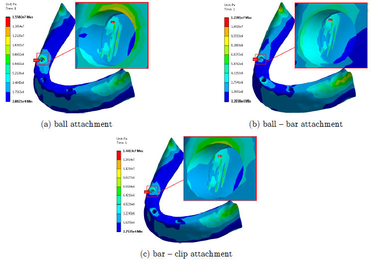
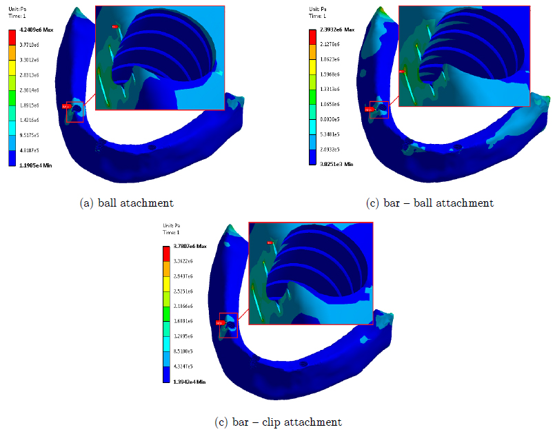
von-Mises stress is used for evaluation of stresses in all postulated treatment designs. In all cases, the highest stress in the bone occurs around the neck of the right side implant, at its upper threads (see Figs. 8-11). The foodstuff is positioned on this side. The value of this stress diminishes rapidly toward the end of implant. According to Figs. 8 and 9, the stress in cortical bone is much higher than that of the cancellous bone. Table 7 summerizes the peak values of von-mises stresses in three applied treatment designs. As observed, the ball design treatment produces the highest von-mises stress in the cortical and cancellous bones.
von-Mises stress distribution in the cancellous bone around the right side implant neck for (a) ball, (b) bar-clip and (c) bar-ball attachment.
von-Mises stress distribution in cortical and cancellous bones at the right side implant for: (a) ball, (b) bar-clip and (c) bar-ball attachment.
Figures 10 and 11 show the complete stress distribution in the cortical and cancellous bones. Location of peak von-Mises stress in each case is marked with an arrow. According to Fig. 11, most of the cancellous bone experiences a uniform state of stress. A close study of Figs. 7-11 reveals that although a ball treatment design produces the lowest overall displacement in overdenture, it results in highest stresses in the cortical and cacellous bones (compared to other treatment designs) during mastication process.
4.3 Stresses in Metal Parts
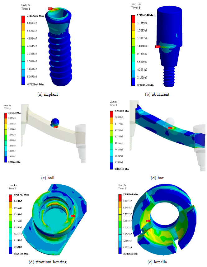
In all treatment models, the induced stresses in metal parts were higher in the right implant, where the foodstuff was positioned. For the ball and bar-ball designs, the highest stress values occur at the neck of right ball abutment (see Figs. 12 and 13), while according to Fig. 14, for the bar- clip design, the peak stress occured the right clip. Table 8 summarizes the maximum von-Mises stresses in the metal parts for the three different treatment designs. These stresses are much higher than those produced in the mandible. Among the three postulated designs, the bar-ball treatment appears to experience the highest von-Mises stress in metal parts. In the remaining two models (ball and bar-clip), the highest von-Mises stresses seem to be in the same order.
4.4 Discussion of Results
Human mandible shows a complex biomechanical behavior under functional loading. Many researchers believe that the deformation of mandible due to muscular forces affects the stresses in peri-implant bone (Parkash et al. (2009)Parkash, V., D'Souza, M., Adhikari, R., (2009). A comparison of stress distribution and flexion among various designs of bar attachments for implant overdentures: a three dimensional finite element analysis, Indian Journal of Dental Research 20: 31-36.; Meijer et al. (1993)Meijer, H.J.A., Starmans, F.J.M., Steen, W.H.A., Bosman, F., (1993). A three dimensional finite element analysis of bone around dental implants in an edentulous human mandible, Archives of Oral Biology 38: 491-96.; Menicucci et al. (1998)Menicucci, G., Lorenzetti, M., Pera, P., Preti, G., (1998). Mandibular implant-retained overdenture: finite element analysis of two anchorage systems, International Journal of Oral Maxillofacial Implants 13: 369-76.; Meijer et al. (1996)Meijer, H.J.A., Starmans, F.J.M., Steen, W.H.A., Bosman, F., (1996). Loading conditions of endosseous implants in an edentulous human mandible: a three dimensional finite element study, Journal of Oral Rehabilitation 23: 757-63.; Cruz et al. (2003)Cruz, M., Wassall, T., Toledo, E.M., da Silva Barra, L.P., de Castro Lemonge, A.C., (2003). Three dimensional finite element stress analysis of a cuneiform-geometry implant, International Journal of Oral Maxillofacial Implants 18: 675-84.). Consequently, application of proper musculature is a necessary step toward simulation of actual results. Additionally, to reach proper results, it is of great importance to accurately model all interactions between mating parts in each treatment. Proper convergence of final results guarantees better simulation of stresses and displacements, and hence, more reliable judgment on results for each treatments.
It is clear that the stability of overdenture is one of the most important requests by the patients. According to the results of this study, in all treatment models, the non-working side of the overdenture slightly arises with respect to the working side (as a result of load application on the foodstuff). Obviously, lower displacements which are due to the nature of each treatment design and position of the anchorage elements can cause better overdenture stability. The bar-ball attachment appears to experience the most overdenture displacement under unilateral masticatory load. For ball treatment design, this displacement appears to be the least, and hence, better overdenture stability.
Based on similar treatment models, the highest stresses in the cortical and cancellous bones for double-implant systems expressed in the past studies, have been lower than the ultimate strength of the respective bones (Baggi et al. (2008)Baggi, L., Cappelloni, I., Maceri, F., Vairo, G., (2008). Stress-based performance evaluation of osseointegrated dental implants by finite element simulation, Simulation Modeling Practice and Theory 16: 971-987.; Hansson and Werke (2003)Hansson, S., Werke, M., (2003). The implant thread as a retention element in cortical bone: the effect of thread size and thread profile: a finite element study Journal of Biomechanics 36: 1247-58.). The results of present study show similar behavior for triple-implant systems used in this work. Hence, bone resorption does not occur. The highest stresses in peri-implant bone concentrate around the neck of the implants (i.e. cortical bone). This result has been also reported in other past studies for other configurations (Daas et al. (2008)Daas, M., Dubois, G., Bonnet, A.S., Lipinski, P., Rignon-Bret, C., (2008). A complete finite element model of a mandibular implant-retained overdenture with two implants: Comparison between rigid and resilient attachment configuration, Medical Engineering Physics 30: 218-225.; Menicucci et al. (1998)Menicucci, G., Lorenzetti, M., Pera, P., Preti, G., (1998). Mandibular implant-retained overdenture: finite element analysis of two anchorage systems, International Journal of Oral Maxillofacial Implants 13: 369-76.; Meijer et al., (1996)Meijer, H.J.A., Starmans, F.J.M., Steen, W.H.A., Bosman, F., (1996). Loading conditions of endosseous implants in an edentulous human mandible: a three dimensional finite element study, Journal of Oral Rehabilitation 23: 757-63.; Cruz et al. (2003)Cruz, M., Wassall, T., Toledo, E.M., da Silva Barra, L.P., de Castro Lemonge, A.C., (2003). Three dimensional finite element stress analysis of a cuneiform-geometry implant, International Journal of Oral Maxillofacial Implants 18: 675-84.; Baggi et al. (2008)Baggi, L., Cappelloni, I., Maceri, F., Vairo, G., (2008). Stress-based performance evaluation of osseointegrated dental implants by finite element simulation, Simulation Modeling Practice and Theory 16: 971-987.). Stress concentration in these regions can be due to higher elastic modulus of the cortical bone in comparison with cancellous bone. Maximum and minimum stresses in the bone (due to presence of implants) appear to occur in the ball and bar-ball attachments, respectively.
Maximum von-Mises stresses in metal parts of the ball and bar-ball attachments occur in the ball abutment. In the bar-clip attachment, maximum stress concentration happens to be at the clip to overdenture junction. Deformation of the overdenture and lifting of non-working side exerts a bending moment to the attachment systems and creates additional stresses in metal parts. Higher stresses in ball abutment of the bar-ball attachment (compared to the two other treatment designs) seem to be due to larger deformation of the overdenture.
5 CONCLUSIONS
In this work stress distribution in three different commercially-available dental implants under functional loads has been numerically investigated by means of static linearly elastic three-dimensional finite-element analysis. Three dimensional geometry of the mandible was generated using computer tomography. Perfect photos of mandible were prepared using CT-scan technology. Three-dimensional numerical models were built-up using RapidForm and SolidWorks softwares. The studied attachment systems included ball, bar-clip and bar-ball. In all cases, three implants supported the overdenture while the right first molar was selected for the position of foodstuff. Comparison of the overdenture displacements showed the importance of the attachment systems. The bar-ball attachment appears to experience the most overdenture displacement under unilateral masticatory load. The overdenture showed less displacement for ball and bar-clip attachments. Among the latter two, the ball treatment design appears to experience the least displacement. This provides better overdenture stability for this design configuration.
The most stressed points in the bone were located around the neck of the working side implant, at its upper threads. In all models, the highest values of von-Mises stresses in the cortical and cancellous bones were lower than their respective ultimate strength values. So, bone resorption does not occur. Additionally, the maximum von-Mises stresses in the peri-implant bone for the bar-clip and bar-ball attachments were about 8 and 21 percent lower than that of the ball attachment. The maximum induced stresses in the metal parts of ball and bar-clip attachments had moderate values. For the bar-ball attachment, the stress levels were higher than those of the other two. Higher displacement of the overdenture with this attachment can be the reason. In the bar-clip design, the induced stresses in the metal parts and peri-implant bone were lower than those of the ball treatment design, although the differences did not appear to be significant. Since in some clinical situations it is required to get more support from edentulous ridge, then, it may be advisable to use bar - ball treatment due to its lower transfer of stresses to the peri-implant bone.
References
- Baggi, L., Cappelloni, I., Maceri, F., Vairo, G., (2008). Stress-based performance evaluation of osseointegrated dental implants by finite element simulation, Simulation Modeling Practice and Theory 16: 971-987.
- Batenburg, R.H.K., Meijer, H.J.A., Raghoebar, G.M., Vissink, A., (1998). Treatment concept for mandibular overdentures supported by endosseous implants: a literature review, International Journal of Oral Maxillofacial Implants 13: 539-45.
- Celik, G., Uludag, B., (2007). Photoelastic stress analysis of various retention mechanisms on 3-implant-retained mandibular overdentures, The Journal Prosthetic Dentistry 97: 229-35.
- Chun, H.J., Park, D.N., Han, C.H., Heo, S.J., Koak, J.Y., (2005). Stress distributions in maxillary bone surrounding overdenture implants with different overdenture attachments, Journal of Oral Rehabilitation 32: 193-205.
- Cruz, M., Wassall, T., Toledo, E.M., da Silva Barra, L.P., de Castro Lemonge, A.C., (2003). Three dimensional finite element stress analysis of a cuneiform-geometry implant, International Journal of Oral Maxillofacial Implants 18: 675-84.
- Cune, M., Burgers, M., van Kampen, F., de Putter, C., van der Bilt, A., (2011). Mandibular overdentures retained by two implants: 10-year results from a crossover clinical trial comparing ball-socket and bar-clip attachments, The Journal of Prosthetic Dentistry 105: 136.
- Daas, M., Dubois, G., Bonnet, A.S., Lipinski, P., Rignon-Bret, C., (2008). A complete finite element model of a mandibular implant-retained overdenture with two implants: Comparison between rigid and resilient attachment configuration, Medical Engineering Physics 30: 218-225.
- Dias, R., Moghadam, M., Kuyinu, E., Jahangiri, L., (2013). Patient satisfaction survey of mandibular two-implant-retained overdentures in a predoctoral program, The Journal of Prosthetic Dentistry 110: 76-81.
- Geckili, O., Bilhan, H., Bilgin, T., (2011). Impact of mandibular two-implant retained overdentures on life quality in a group of elderly Turkish edentulous patients, Archives of Gerontology and Geriatrics 53: 233-36.
- Grageda, E., Rieck B., (2014). Metal-reinforced single implant mandibular overdenture retained by an attachment: A clinical report The Journal of Prosthetic Dentistry 11: 16-19.
- Guda, T., Ross, T.A., Lang, L.A., Millwater, H.R., (2008). Probabilistic analysis of preload in the abutment screw of a dental implant complex, The Journal Prosthetic Dentistry 100: 183-93.
- Hansson, S., Werke, M., (2003). The implant thread as a retention element in cortical bone: the effect of thread size and thread profile: a finite element study Journal of Biomechanics 36: 1247-58.
- Harder, H., Wolfart, S., Egert, C., Kern, M., (2011). Three-year clinical outcome of single implant-retained mandibular overdentures-Results of preliminary prospective study, Journal of dentistry 39: 656-61.
- Huang, H.L., Hsu, J.T., Fuh, L.J., Tu, M.G., Ku, C.C., Shen, Y.W., (2008). Bone stress and interfacial sliding analysis of implant designs on an immediately loaded maxillary implant: A non-linear finite element study, Journal of Dentistry 36: 409-17.
- Korioth, T.W.P., Hannam, A.G., (1994). Deformation of the human mandible during simulated tooth clenching, Journal of Dentistry Research 73: 56-66.
- Liu, J., Pan, S., Dong, J., Mo, Z., Fan, Y., Feng, H., (2013). Influence of implant number on the biomechanical behavior of mandibular implant-retained/supported overdentures: A three-dimensional finite element analysis, Journal of dentistry 41: 241-9.
- Meijer, H.J.A., Starmans, F.J.M., Steen, W.H.A., Bosman, F., (1994). A three-dimensional finite element study on two versus four implants in an edentulous mandible, International Journal of Prosthodontics 7: 271-79.
- Meijer, H.J.A., Starmans, F.J.M., Steen, W.H.A., Bosman, F., (1993). A three dimensional finite element analysis of bone around dental implants in an edentulous human mandible, Archives of Oral Biology 38: 491-96.
- Meijer, H.J.A., Starmans, F.J.M., Steen, W.H.A., Bosman, F., (1996). Loading conditions of endosseous implants in an edentulous human mandible: a three dimensional finite element study, Journal of Oral Rehabilitation 23: 757-63.
- Menicucci, G., Lorenzetti, M., Pera, P., Preti, G., (1998). Mandibular implant-retained overdenture: finite element analysis of two anchorage systems, International Journal of Oral Maxillofacial Implants 13: 369-76.
- Ohida, M., Yoda, K., Nomura, N., Hanawa, T., Igarashi, Y., (2010). Evaluation of the static frictional coefficients of co-cr and gold alloys for cone crown telescope denture retainer applications, Dental materials Journal 29: 706-12.
- Pan, Y.H., Yu, L.M., Lin, T.M., (2014). Dental implant-retained mandibular overdenture therapy: A clinical study of patients' response, Journal of Dental Sciences 9: 118-24.
- Parkash, V., D'Souza, M., Adhikari, R., (2009). A comparison of stress distribution and flexion among various designs of bar attachments for implant overdentures: a three dimensional finite element analysis, Indian Journal of Dental Research 20: 31-36.
- Takayama, Y., Yamada, T., Araki, O., Seki, T., Kawasaki, T., (2001). The dynamic behaviour of a lower complete denture during unilateral loads: Analysis using the finite element method, Journal of Oral Rehabilitation 28: 1064-74.
- Tao, C., Guifeng, S., Jingyu, H., Xiaoji, H., Yining, W., Yan-Fang, R., (2012). Patient satisfaction and masticatory efficiency of single implant-retained mandibular overdentures using the stud and magnetic attachments, Journal of dentistry 40: 1018- 23.
- Tokuhisa, M., Matsushita, Y., Koyano, K., (2003). In vitro study of a mandibular implant overdenture retained with ball, magnet, or bar attachments: comparison of load transfer and denture stability, International Journal of Prosthodontics 16: 128-34.
- Tolga, T., Murat, Y.S., (2015). The effect of implant number and position on the stress behavior of mandibular implant retained overdentures: A three-dimensional finite element analysis, Journal of Biomechanics 48: 2102-09.
Publication Dates
-
Publication in this collection
Dec 2016
History
-
Received
11 July 2016 -
Accepted
12 Oct 2016