Abstract
The Hercílio Luz suspension bridge, built in 1926, has been out of service since 1991 due to high corrosion levels and structural element impairment. A complete rehabilitation project was developed which included the replacement of the impaired items and foundation strengthening. For this, an auxiliary structure was employed to support the central span during the rehabilitation process. A carefully studied load transfer process, where the central span loading is transferred from the eye-bar towards the auxiliary structure will be performed. For this purpose, a synchronized jacking sequence will be used, which was predefined by means of numerical model analysis. All structural elements had their designs evaluated and some geometric changes were implemented. This paper presents all the methodology developed in the rehabilitation project of Hercilio Luz bridge, as well as the development stages up to the present date.
Keywords:
Bridge rehabilitation; Structural impairment evaluation; Load transfer; Synchronized jacking
1 INTRODUCTION
In the past years, the rehabilitation process of civil engineering structures such as bridges and overpasses has gained relevance (Costa et al., 2014Costa, B.J.A., Magalhães, F., Cunha, A,. Figueiras, J. “Modal analysis for the rehabilitation assessment of the Luiz I Bridge”. Journal of bridge engineering, v. 19, Issue 12. 2014.). Several structures are reaching their design life in Europe and America, which leads the engineers to a new concern: the need to develop rehabilitation projects aiming to guarantee structural integrity and design life increase (Radomski, 2013Radomski, W. “Bridge rehabilitation”. Stahlbau, Vol. 72. Issue 7, p.506-512, 2013.). Rehabilitation is usually an attractive alternative, once it represents between 10% and 30% of the total cost of a similar new structure for most cases (Shim et al., 2015Shim, H.S., Lee, S.H. “Developing a probable cost analysis model for comparing bridge deck rehabilitation methods”. KSCE Journal of Civil Engineering, p 1-9, 2015.).
The Hercilio Luz suspension bridge construction began on November 14th, 1922 and was opened to traffic on May 13th, 1926. The bridge built over the Atlantic Ocean connects the continent to the island (Fig. 1). Initially, it was conceived to support a road, an electric railway and the city of Florianopolis water supply. The bridge is 819.5 m long and its length is composed of: 259 m of island overpass, 339.5 m of main span (Fig. 2) and 221.0 m of continent overpass. The main span makes the Hercilio Luz Bridge one of the largest in the world and one of the last possessing eye-bars incorporated to a truss.
Figure 3 presents the main elements that compose the bridge. The steel structure has the approximated weight of five thousand tons. The foundations and pillars were built with 14.250 m³ of concrete. The metallic pylons are 75 m high above sea level and the main span is 32 m high above sea level.
The main span is composed by a truss whose maximal height is reached at one quarter of the span, where the bending moment is maximal. In the truss central part, between one quarter and three quarters of the span, the eye-bars are incorporated to the truss, where they work as an upper chord. Outside the span’s central region, the truss upper chord is connected to the eye-bars through vertical hangers (Steinman, 1922Steinman, D.B. “A practical treatise on suspension bridges”, London, John Wiley e Sons, Inc. 1922.).
Visual inspections and non-destructive tests indicated the need for replacement of the eye-bars, eye-bar supports, pylon bases, hangers and some truss elements. To make the replacements possible, an auxiliary structure under the main span truss was conceived. This structure will temporarily hold the main span. The load transfer from the eye-bar to the auxiliary structure will be performed with a synchronized jacking sequence. The structure will be reassembled thought a reverse jacking sequence.
2 BRIDGE ORIGINAL DESIGN
The bridge original design was conceived in the 1920s by the American engineers H. D. Robinson and D. B. Steinman. The steel structure was manufactured in the United States and assembled in Brazil by the company American Bridge. Figure 4 shows the three different structural solutions evaluated: a suspension bridge with incorporated eye-bars (the retained solution, judged as the most cost-effective solution at the time), a standard suspension bridge and a truss bridge.
Structural solutions evaluated by the original designers (Steinman, 1926Steinman, D.B., Grove, W. G., “The eye-bar suspension bridge at Florianopolis”, Brazil, Paper no. 1662, American Society of Civil Engineers, Vol. 92, p.266, 1926.).
Figure 5 shows the anchorage massifs building, where it is possible to observe the concrete forms and the anchorage of eye-bars inside the massif.
Anchorage massifs building (Steinman, 1926Steinman, D.B., Grove, W. G., “The eye-bar suspension bridge at Florianopolis”, Brazil, Paper no. 1662, American Society of Civil Engineers, Vol. 92, p.266, 1926.).
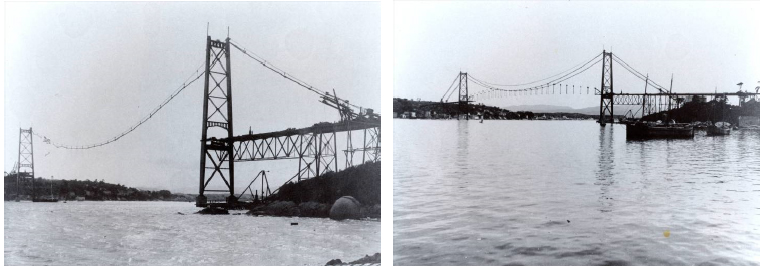
After the foundations were finished, the structural assembly of the access spans was performed. Figure 6 (a) shows the beginning of the main span assembly with the pylon assembly and the employment of auxiliary cables. After the eye-bar assembly, the truss elements are individually assembled (Fig. 6 (b)) until the complete closing of the plane trusses (Fig. 7).
Main span assembly pictures (a) The pylon and the employment of auxiliary cables (b) Truss isolated elements assembly (Steinman, 1926Steinman, D.B., Grove, W. G., “The eye-bar suspension bridge at Florianopolis”, Brazil, Paper no. 1662, American Society of Civil Engineers, Vol. 92, p.266, 1926.).
Plane trusses assembly (Steinman, 1926Steinman, D.B., Grove, W. G., “The eye-bar suspension bridge at Florianopolis”, Brazil, Paper no. 1662, American Society of Civil Engineers, Vol. 92, p.266, 1926.).
After the plane trusses closure, the eye-bars are the only truss element at work. They are the only elements loaded due to the chosen operational assembly sequence. The other truss elements are in service only after the assembly of transverse elements (bracing elements and diaphragms) and bridge deck. Figure 8(a) presents the assembly of the metallic elements that support the bridge deck. Figure 8(b) presents the finished wood deck.
Deck photos (a) Support metallic elements assembly (b) Complete main span deck (Steinman, 1926Steinman, D.B., Grove, W. G., “The eye-bar suspension bridge at Florianopolis”, Brazil, Paper no. 1662, American Society of Civil Engineers, Vol. 92, p.266, 1926.).
3 STRUCTURAL IMPAIRMENT EVALUATION
The Hercilio Luz Bridge was temporarily put out of service for the first time after the rupture of only one eye-bar. This event generated the intensification of the structural impairment evaluation. In 1991, the bridge was permanently put out of service.
The last visual inspections were made between 2009 and 2013. Figure 9 presents the fissures and the high corrosion level at the pylon base. The high corrosion state of the steel deck is presented in Figure 10.
Due to the fact that the original project is very old, there were no records of the composition of the steel employed in the construction. In order to characterize the kinds of steel present in the structure, hardness tests were performed in the main structural elements, such as pylons, eye-bars and truss elements (Fig. 11). The yield limits of the materials were defined based on the characterization results, in accordance with ASTM standard (ASTM E140-05e1, 2005ASTM E140-05e1, “Standard Hardness Conversion Tables for Metals Relationship Among Brinell Hardness, Vickers Hardness, Rockwell Hardness, Superficial Hardness, Knoop Hardness, and Scleroscope Hardness”. ASTM International, (2005).).
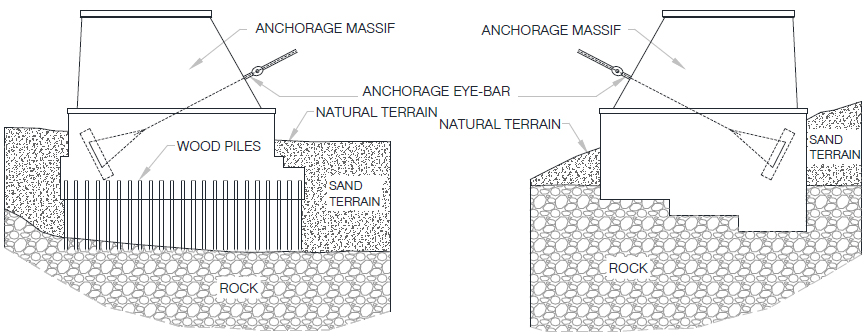
During inspections, surface wear was found in the concrete structures. Furthermore, it was found that the blocks and anchorage massifs were made of Cyclopean concrete. The original foundation project indicates that one of the anchorage massifs is set directly over the rock and the other over wood piles (Fig. 12). The wood piles are inaccessible. Therefore, it was not possible to verify their state of preservation and the structural integrity of the wood piles, due to age, cannot be guaranteed.
4 BRIDGE STRUCTURE REHABILITATION PROJECT
The thickness of some structural elements was reduced due to the high corrosion state of the structure and, as a consequence, the stress level increased. For that reason, several structural elements will need to be replaced, such as eye-bars, eye-bar supports, pylon bases, hangers, deck and some truss elements.
All foundations should be reinforced because of incertitude concerning their structural impairment. The blocks and anchorage massifs will be reinforced through adding a new layer of concrete around them and the construction of concrete piles under them.
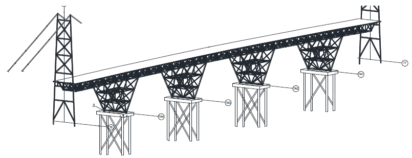
A state of minimal structure loading should be reached so that the steel elements replacement and foundation retrofit may take place. For that purpose, a solution where the main span is supported by an auxiliary structure was designed. This approach makes the rehabilitation process safe, once the main span is completely supported by the auxiliary structure. This structure is composed by a space truss with four bases, supported by independent foundations (Fig. 13).
Another alternative based on, based on the support of the central span by auxiliary cables placed over the eye-bars was evaluated. This alternative is similar to the procedure adopted in the initial assembly of the structure. However, this procedure does not reduce the loads at the pylons’ foundations. This solution would demand even bigger reinforcements and bigger jacking loads for bearing replacement. This solution is also less safe than the adopted one, because it relies on damaged elements to sustain and stabilize the structure.
4.1 Load Transfer
Once the inferior auxiliary structure is assembled, the load transfer from the eye-bar to this structure must be performed. This procedure will be performed through the synchronized vertical jacking of 54 truss points. The bridge displacements through jacking will be performed in a parabolic form. The whole process is monitored trough topographic survey and data analysis from sensors added to the structure, such as extensometers, displacement sensors, thermometers, among others.
To define the geometric configuration needed to minimize the efforts at the eye-bars, a geometric non-linear finite elements model at (SAP2000®, 2009SAP 2000, v.14.1.0. Computers and Structures, Inc, 2009.) software was developed. Incremental displacements are imposed on the truss inferior part aiming to obtain minimal loading at the eye-bars. Evaluation of those displacements will provide the displacements that need to be imposed on the structure by the jacking system. The confirmation of the hypothesis of zero loading in each element is to be verified experimentally, in loco, by the analysis of the strains measured by strain gauges.
Basically, the load transfer process is executed in two main phases, listed below.
- Phase 1: Jacking of 54 points in a parabolic form, with upward displacements, aiming to reach zero loading condition to the truss external eye-bars. After phase 1 is completed, just the external eye-bars can be disconnected from the truss. Even with the disconnected truss structure, there will be a residual tension load in the internal eye-bars (superior chords of the truss) due to the erection order of the bridge. In disassembly, the structural system of the truss does not enable the relieve of the tension efforts existent in its superior chords (composed by eye-bars). As can be seen in Figure 3b, the eye-bars are subject to tension loads before the assembly of the truss has been completed, due to the self weight of the elements. A total upward displacement of 550 mm must be considered in the middle span in order to annul the tension load in external eye-bars. The displacement will be made in 10 steps of 55 mm each (Fig. 14).
- Phase 2: After disconnecting the truss from the external eye-bars, the 54 points must be jacked in a parabolic form, through downward displacements, aiming to reach compression loading at the truss superior chord. These imposed displacements are applied through six steps - Fig. 15 - and their values vary from 330 mm (first step) to 30 mm (last step) in the middle span. At each step, the added compression load will annul the residual tension load in the eye-bar symmetrical pairs, from the extremity towards the center, and the elements can be sequentially removed.
To disconnect the truss eye-bars at the end of Phase 1, the main span pylons should remain to stabilize the set.
Once the structure is disconnected and the internal eye-bars are opened, all the replacements and reinforcements can be performed. After rehabilitation, the structure should be reassembled in a reverse sequence.
4.2 Changes in Concrete Structures and Foundations
The access span foundations were originally designed as rock supported concrete blocks. Since it is not possible to verify the real condition of the block support, a block reinforcement project was developed. The blocks will be expanded by being wrapped by a new bigger block that will be supported by 450 mm diameter concrete piles (Fig. 16).
The reinforcement of the central span pylon foundations will follow the same logic as the one employed for the access span foundations. The difference is that steel bars will connect the old block with the new wrapping one. Pre-casted concrete cofferdams will be employed around the existent block to build the reinforcement.
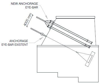
The anchorage massif, which is set over the rock, will be used and only its surface repaired, while the anchorage massif set over wood piles will be demolished and integrally rebuilt with the original geometric shape. Figure 17 shows the position of the new anchorage eye-bars in the massif set over the rock.
4.3 Changes in Steel Structures
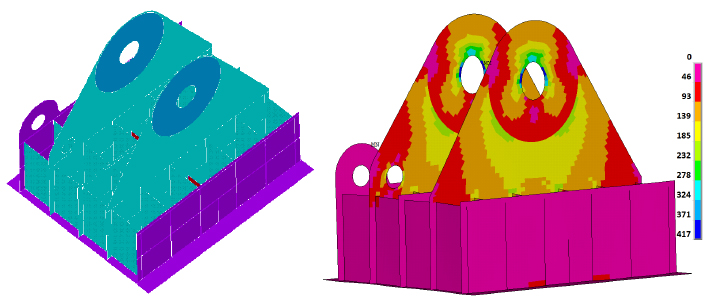
The Hercilio Luz Bridge steel structures were the most affected by the time effect. The bridge deck, initially composed by steel beams covered by wood plates, will be replaced by an orthotropic steel deck. All the elements with complex geometries had their resistance evaluated based on FEM models. The cast parts, such as the pylon base and the eye-bar supports will be replaced by new cast parts. Figure 18 presents the stress diagram at the pylon base. Figures 19 and 20 present the stress diagrams of the eye-bar support and the eye-bar anchorage on the massif, respectively.
The eye-bars will be replaced by new machined bars, made by high resistance steel with yield limit equal to 980 MPa. Some changes in the eye-bar geometry were analyzed, but the original design with circular hole was maintained. Figure 21 presents the geometry for the whole eye-bar, which total length is equal to, approximately, 15000 mm.
5 CURRENT STATE OF BRIDGE REHABILITATION WORKS
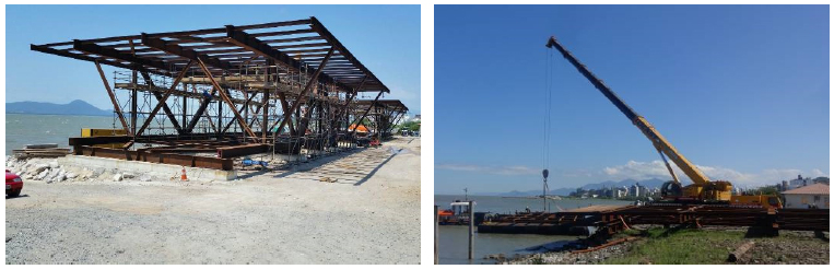
Currently (01/06/2016), the inferior auxiliary truss assembly has been concluded. The load transfer process is predicted to be initiated in August, 2017. After this stage is completed, the load transfer process will be initiated. Once the load transfer process completed, the proper rehabilitation work will start. Retrofitting and replacement of damaged steel elements, foundations strengthening and reverse load transfer will be performed. Figures 22 to 24 present the auxiliary structure assembly in several stages.
6 CONCLUSIONS
Main conclusions:
-
- Due to high corrosion levels, the Hercilio Luz Bridge needs to be rehabilitated and repaired to be reopened to traffic.
-
- The rehabilitation project was conceived considering an auxiliary structure under the bridge main span. A load transfer process project considers an auxiliary structure under the bridge main span. This structure will temporarily hold the main span. The load transfer from the eye-bar to the auxiliary structure will be performed with a synchronized jacking sequence of 54 points of the main span truss.
-
- After the load transfer process, all the structural interventions may be performed. The foundations will be reinforced by the lateral expansion of the blocs and construction of new concrete piles. The main truss bars, access span and pylon elements will be either reinforced or replaced. The main structural elements such as eye-bars, eye-bar supports, pylon bases and eye-bar anchors will be integrally replaced.
-
Structure reassembly should follow the reverse sequence of the steps of the load transfer from the eye-bars to the auxiliary truss.
Acknowledgments
The authors gratefully acknowledge RMG Engenharia and DEINFRA-SC (Departamento Estadual de Infraestrutura do estado de Santa Catarina) for their participation in the project.
References
- ASTM E140-05e1, “Standard Hardness Conversion Tables for Metals Relationship Among Brinell Hardness, Vickers Hardness, Rockwell Hardness, Superficial Hardness, Knoop Hardness, and Scleroscope Hardness”. ASTM International, (2005).
- Costa, B.J.A., Figueiras, J.A. “Rehabilitation and condition assessment of a centenary steel truss bridge”. Journal of Constructional Steel Research, v. 89, p.185-197, 2014.
- Costa, B.J.A., Magalhães, F., Cunha, A,. Figueiras, J. “Modal analysis for the rehabilitation assessment of the Luiz I Bridge”. Journal of bridge engineering, v. 19, Issue 12. 2014.
- Radomski, W. “Bridge rehabilitation”. Stahlbau, Vol. 72. Issue 7, p.506-512, 2013.
- SAP 2000, v.14.1.0. Computers and Structures, Inc, 2009.
- Shim, H.S., Lee, S.H. “Developing a probable cost analysis model for comparing bridge deck rehabilitation methods”. KSCE Journal of Civil Engineering, p 1-9, 2015.
- Steinman, D.B. “A practical treatise on suspension bridges”, London, John Wiley e Sons, Inc. 1922.
- Steinman, D.B., Grove, W. G., “The eye-bar suspension bridge at Florianopolis”, Brazil, Paper no. 1662, American Society of Civil Engineers, Vol. 92, p.266, 1926.
Publication Dates
-
Publication in this collection
Mar 2017
History
-
Received
27 Sept 2016 -
Reviewed
03 Feb 2017 -
Accepted
21 Feb 2017