
ABSTRACT
This paper deals with a spherical cavity excavated in infinite homogeneous and isotropic strain-softening rock mass subjected to a hydrostatic initial stresses. By simplifying the strain-softening process of the post-failure region as a Multi-step Brittle-Plastic model (MBPM), analytical solutions of the spherical cavity are derived with the consideration of the deterioration of elastic parameters. Meanwhile, critical deterioration conditions of elastic parameters are established theoretically. Both Mohr-Coulomb (M-C) and Hoek-Brown (H-B) criteria are included in the analysis. The results are compared with those obtained by former numerical methods, and the solutions are validated. Moreover, the presented results show that deteriorated elastic parameters for post-failure rock mass only has a little influence on stresses, softening radius and residual radius, but influences the deformation significantly.
KEY WORDS
Spherical cavity; strain-softening; Elasto-plastic coupling; Yield criterion; Analytical solution
1. Introduction
Displacements and stresses distributions are two of the most important information for underground engineering, for that it can provide a theoretical foundation for geotechnical engineering optimism design and stability evaluation. In past few years, many scholars have developed series of (semi-)analytical and numerical solutions for circular openings and spherical cavities.
Brown et al. firstly obtained the closed-form solution of circular openings in elasto-brittle-plastic Hoek-Brown (H-B) medium [ 11 Brown ET, Bray JW, Ladanyi B, Hoek E. Ground response curves for rock tunnels. J Geotech Geoenviron 1983;109, 15–39. ]. Later, more studies were done in this area (e.g., Reed [ 22 Reed MB. Stresses and displacements around a cylindrical cavity in soft rock. IMA J App Math 1986; 36, 223–45. ]; Ogawa and Lo [ 33 Ogawa T, Lo KY. Effects of dilatancy and yield criteria on displacements around tunnels. Can Geotech J, 1987; 24:100–13. ]; Gates [ 44 Gates DJ, Strain softening around cavities in rock-like materials. Mech Mater 1990; 8, 309-331. ]; Sharan [ 55 Sharan SK. Elastic-brittle-plastic analysis of circular openings in Hoek-Brown media. Int J Rock Mech Min Sci 2003; 40, 817-24. , 66 Sharan SK. Analytical solutions for stresses and displacements around a circular opening in a generalized Hoek-Brown rock. Int J Rock Mech Min Sci 2008; 45,78-85. ]; Park and Kim [ 77 Park KH, Kim YJ. Analytical solution for a circular opening in an elastic-brittle-plastic rock. Int J Rock Mech Min Sci 2006; 43, 616-22. ]; Yuan and Chen [ 88 Yuan WB, Chen J. Analysis of plastic zone and loose zone around opening in softening rock mass. Journal of China Coal Society 1986; 3, 77-86. ]; Jiang et al. [ 99 Jiang BS,Zhang Q,He YN, Han LJ. Elastioplastic analysis of cracked surrounding rocks in deep circular openings. Chinese Journal of Rock Mechanics and Engineering 2007; 26, 982–986. ]; Yu [ 1010 Yu HS. Cavity Expansion Methods in Geomechanics. Dordrecht: Kluwer, 2000. ]). However, most of those solutions are based on the common elasto-perfectly-plastic and elasto-brittle-plastic models, because those solutions can be easily obtained using simple mathematical methods. However, most of the geotechnical materials display strain-softening behavior in the post-failure region. Therefore, the normally used elasto-perfectly plastic model and elasto-brittle-plastic model can’t well represent the actual failure process. Brown et al. were the earliest ones to analyze the stresses and displacements of circular openings excavated in the strain-softening rock mass. But, the assumption of constant elastic strain in the plastic region, which should obey the generalized Hooke's law, leads to a poor accuracy of the results. And Wang points out that Brown et al.’s solution is difficult to predict the plastic radius [ 1111 Wang Y. Ground response of circular tunnel in poorly consolidated rock. Journal of Geotechnical Engineering 1996; 122, 703-8. ]. Carranza-Torres and Fairhurst’s solution for H-B rock mass, which is based on the so-called self-similarity of H-B criterion, is theoretically rigorous. But, it seems rather complicated for practical use and is applicable only to the elasto-perfectly-plastic case [ 1212 Carranza-Torres C, Fairhurst C The elasto-plastic response of underground excavations in rock masses that satisfy the Hoek–Brown failure criterion. Int J Rock Mech Min Sci 1999; 36,777–809. ]. Alonso et al. presented comprehensive reviews about modeling strain-softening behavior while studying ground response curve (GRC) in strain-softening M-C and H-B rock masses by a self-similar method, which was regarded as the most rigorous one [ 1313 Alonso E, Alejano LR, Varas F, Fdez-Manin G, Carranza-Torres C. Ground response curves for rock masses exhibiting strain-softening behavior. Int J Numer Anal Met 2003; 27,1153-85. ]. Additionally, some researchers proposed the simplified model by negative Young’s modulus in the post-failure region, but there is no physical meaning for the negative Young’s modulus [ 1414 Bazant ZP. Instability, ductility, and size effect in strain-softening concrete. Journal of the Engineering Mechanics Division 1976; 102, 331-44. ]. Park et al. improved Brown et al.’s solution and presented a numerical differential procedure, which is accurately correct [ 1515 Park KH, Tontavanich B, Lee JG. A simple procedure for ground response curve of circular tunnel in elastic-strain softening rock masses. Tunn Undergr Sp Tech 2008; 23, 151-9. ]. At the same time, Lee and Pietruszczak obtained the displacement and stress solutions of circular openings and spherical cavities by gradually relieving the supporting pressure using a finite difference numerical procedure [ 1616 Lee YK, Pietruszczak S. A new numerical procedure for elasto-plastic analysis of a circular opening excavated in a strain-softening rock mass. Tunn Undergr Sp Tech 2008; 23, 588-99. ]. Wang et al. analyzed the strain-softening process of circular openings by semi-analytical and semi-numerical method [ 1717 Wang SL, Yin XT, Tang H, Ge XR. A new approach for analyzing circular tunnel in strain-softening rock masses. Int J Rock Mech Min Sci 2010; 1, 170-8. ]. The results obtained by the above methods are in accordance with each other. On the basis of the presented approach, Wang et al. also implemented it in a finite element code, which is used for solving strain-softening problems [ 1818 Wang SL, Zheng H, Li CG, Ge XR. A finite element implementation of strain-softening rock mass. Int J Rock Mech Min Sci 2011; 48, 67-76. ]. The numerical results seem very satisfactory.
As we see, all of the solutions for strain-softening rock mass are based on semi-analytical and numerical method, no analytical solutions are available. Additionally, most of the indoor and field tests show that material properties of rock mass change during the failure process, not only strength parameters but also elastic parameters, i.e. Yong’s modulus and Poisson’s ratio. This is the so-called elasto-plastic coupling effect. Generally speaking, the effect of Young’s modulus is analyzed in two ways. One is the pressure-dependent Young’s modulus model (PDM) in which Young’s modulus depends on the confining pressure or minor principal stress (Kulhawy [ 1919 Kulhawy FH. Stress deformation properties of rock and rock discontinuities. Eng Geol 1975; 9, 327-50. ]; Brown et al. [ 2020 Brown ET, Bray JW, Santarelli FJ. Influence of stress-dependent elastic moduli on stresses and strains around axisymmetric boreholes. Rock Mech Rock Eng 1989; 22, 189 –203. ]; Asef and Reddish [ 2121 Asef MR, Reddish DJ. The impact of confining stress on the rock mass deformation modulus. Geotechnique 2002; 52, 235-41. ]; Verman et al. [ 2222 Verman M, Singh B, Viladkar MN, Jethwa JL. Effect of tunnel depth on modulus of deformation of rock mass. Rock Mech Rock Eng 1997; 30, 121-7. ]; Zhang et al [ 2323 Zhang Q, Zhang CH, Jiang BS, Li N, Wang YC. Elastoplastic coupling solution of circular openings in strain-softening rock mass considering pressure-dependent effect. Int J Geomech, 2018; 18(1), 04017132 ]); the other is the radius dependent Young’s modulus (RDM) in which Young’s modulus is supposed to be the function of radius (Ewy and Cook [ 2424 Ewy RT, Cook NGW. Deformation and fracture around cylindrical openings in rock-I: Observations and analysis of deformations. Int J Rock Mech Min Sci 1990; 27, 387-407. ]; Nawrocki and Dusseault [ 2525 Nawrocki PA, Dusseault MB. Modelling of damaged zones around openings using radius-dependent Young’s modulus. Rock Mech Rock Eng 1995; 28, 227-39. ]). Additionally, under the seepage effects [ 2626 Liu RC, Li B, Jiang Y. Critical hydraulic gradient for nonlinear flow through rock fracture networks: the roles of aperture, surface roughness, and number of intersections. Adv Water Resour 2016, 88: 53-65. - 2727 Liu RC, Jiang YJ, Li B, Wang X. A fractal model for characterizing fluid flow in fractured rock masses based on randomly distributed rock fracture networks. Comput Geotech 2015, 65: 45-55. ], the progressive failure process may be more significant. However, the two models can hardly be solved with analytical method. Considering the different tensile and compressive Young’s modulus, Luo et al. obtained the closed-form solutions of spherical cavities in elasto-brittle-plastic rock mass [ 2828 Luo ZY, Zhu XR, Gong X. Expansion of spherical cavity of strain-softening materials with different elastic moduli of tension and compression. J Zhejiang Univ-sc A 2007; 8, 1380-7. ]. The difficulty of analytical methods for strain-softening rock mass is the coupling effect between softening index and material properties. In view of this, the Multi-step Brittle-Plastic model (MBPM) is proposed to solve the stress, strain, and displacement in the post-failure region for the spherical cavity. Moreover, the deterioration process of elastic parameters and strength parameters are also considered.
2. Problem description
2.1. Physical model
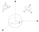
Figure 1 shows a spherical cavity with radius R0 excavated in isotropic rock mass subject to a hydrostatic stress field p. The supporting stress σ0 uniformly distributed along the excavation surface. In the present problem, the polar coordinate is considered. Then, the spherical cavity turns to be a spherically symmetric problem, in which the stresses, strains and displacements in the surrounding rock are only functions of radius r. Moreover, the tangential stresses are uniform in each direction, i.e. σθ =σφ.
Generally speaking, the post-failure rock mass is composed of two regions. One is the strain-softening region, and the other is the residual region. In the residual region, material parameters take the residual value and they are constant. But, the material properties vary with the deformation changes in the strain-softening process. Usually, a softening index, which is determined by plastic strains, is defined to relate the strength parameters to deformation. So, the strain-softening character usually induces difficulties for both analytical and numerical methods. In the case where the closed-form solutions of spherical cavities in elasto-brittle-plastic rock mass are available, the strain-softening problem can be easily deal with MBPM.
Figure 2 shows the simplified mechanical model for spherical cavities excavated in the strain-softening rock mass, and the post-failure rock is divided into k spherical shells. If number k is large enough, each spherical shell would be so thin that its material properties can be approximately assumed as uniform. In this way, each spherical shell is assumed to be a separate perfectly-plastic material. Moreover, the simplified mechanical model converges to the actual strain-softening model with increasing k .

(a) Simplified physical model for a spherical cavity and (b) Simplified mechanical model for a spherical cavity
In this paper, the subscript “(i)” is employed to denote the material property parameters and variables of the ith shell, and symbol “(·)” denotes the corresponding variable is a function of radius r. The default value of i varies from 1 to k. Meanwhile, the compressive stress is supposed to be positive, and the tensile stress to be negative.
2.2. Yield criteria
The linear Mohr-Coulomb criterion (M-C) and the non-linear Hoek-Brown criterion (H-B) are commonly used in geotechnical engineering. Here, both criteria are employed.
The linear M-C yield criterion can be written in principle stress space as
where and are respectively the major and minor principal stress; η is an internal parameter indicating the softening process; α =(1+sinφ)/(1-sinφ), Y =2·c·cosφ/(1-sin φ), c and φ, which are functions of η, are cohesion and internal friction angle, respectively.
The nonlinear H-B yield criterion is expressed in the principal stress space as
where m and s are strength parameters, and they are also functions of η; σc is the uniaxial compressive strength of the intact rock.
3. Stresses and displacements in the elastic region
3.1. Lame’s solution for the elastic region
The elastic solution (Lame’s solution) for a spherical cavity with radius Rk, which is excavated in infinite homogeneous and isotropic rock mass subjected to hydrostatic initial stress p, can be written in the following form.
where σk is the internal pressure of the spherical cavity, and Gk is the shear modulus of the medium. , and are the radial stress, the tangential stress and radial displacement, respectively.
3.2. Critical internal pressure σk
Stress and displacement in the surrounding rock mass depend on the initial stress and internal supporting pressure. If the supporting pressure is lower than its critical value, a post-failure region would form around the surrounding rock mass.
At the interface of the elastic and strain-softening zone, properties of rock mass take the peak value. By substituting elastic stress components of Equation (2) at r=Rk into Equation (1) , critical supporting pressure for M-C rock mass and H-B rock mass can be obtained as follows:
The superscript “M-C” and “H-B ” denotes the M-C and H-B rock mass, respectively. Meanwhile, Equation (3) denotes the critical supporting pressure is the only function of p and material properties, but independent of radius Rk. So, once plastic region forms, the radial stress at the elastic-softening interface can be determined by Equation (3) .
Although solutions for elasto-perfectly-plastic and elasto-brittle-plastic models can be easily obtained, solutions for softening rock mass can hardly explicitly expressed because of the varying properties. In the next section, an efficient approach is proposed for the complicated strain-softening process.
4. Stresses and displacements in the post-failure region
As shown in Figure 2 (b), the strain-softening process is simplified as multi brittle-plastic steps with uniform and isotropic material in each step. The elasto-perfectly plastic analysis, which would be firstly presented in this section, is the foundation of a strain-softening process for the proposed analytical method.
4.1. Theoretical equations
In each spherical shell, the stresses satisfy the equilibrium equation. If the body force is neglected, it can be formulated as
Since in the present problem, Equation (4) can be rewritten as
In each spherical shell, the geometric equations can be expressed as
Because of the symmetry of the spherical cavity, the tangential stresses ( ) and radial stress ( ) are the principal stresses, namely, and . Then, the yield criteria for the ith spherical shell can be written as
for M-C criterion, and
for H-B criterion.
When the yield criteria are satisfied, the nonlinear deformation would occur. In order to get the plastic strain, the following plastic potential function is employed.
where , and ψi is the dilation angle.
Additionally, the stress and displacements of rock mass should be continuous at the interface of adjacent spherical shells
4.2. Stress in each post-failure shell
By submitting Equation (7a) into equilibrium Equation (5) , the differential equation of radial stress can be obtained. By solving the differential equation and using boundary conditions of Equation (9), the stresses in the surrounding rock mass can be formulated as
where , , and is the radial stress at r=Ri-1, i.e. .
In the same way, when H-B yield criterion is considered, the stresses in each spherical shell can be formulated as
where , .
4.3 Displacement in each post-failure shell
The total strain is composed of elastic strain and plastic strain, and it can be written as
By means of Equation (8) and Equation (12) , the plastic components of the radial strain and tangential strain can be related by
Substitutions of Equation (6) into Equation (12) and then into Equation (13) result in the compatibility function for radial displacement.
where .
The radial displacement at the elasto-plastic interface can be determined by Equation (2) , i.e. . For the ith shell, if the displacement at outer radius is known as ui, the displacement of the differential Equation (14) can be obtained.
The elastic strain is supposed to obey the generalized Hooke’s law. Considering the symmetry of this problem, the elastic strains induced by excavation can be expressed as
where E is Young’s modulus.
Then the function in Equation (14) can be rewritten as
Using Equation (10) in the ith spherical shell, the function fi (r) can be expressed as
where , .
Substituting Equation (11) and Equation (16) into Equation (17) , function fi(r) for H-B criterion can be expressed as
where , , .
Then, substitution of Equations (18) and (19) into Equation (15) , respectively and integral manipulation, displacement for the ith spherical shell for both M-C and H-B rock mass can be written in a compact way as follows.
where , , , , .
5. Calculation of spherical shell radii
5.1. Evolution of material parameters
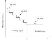
Whether material parameters changes with internal variables or not is the main difference between strain-softening model and elasto(-brittle)-plastic model. In strain-softening rock mass, material parameters evolve as deformation continues in the post-peak region. Different rock mass should have different strength evolution law. C.D. Martin proposed the cohesion weakening- frictional strengthening model (CWFS), in which cohesion weakens and frictional strength increases with the accumulation of deformation [ 2929 Martin CD, Chandler NA. The progressive fracture of Lac du Bonnet granite. Int J Rock Mech Min Sci 1994; 31, 643-59. ]. The wave velocity tests show that elastic modulus and Poisson’s ratio also change with deformation. In reality, the evolution law of rock mass can be obtained through loading-unloading tests in the laboratory. For simplicity, a linear deterioration process of material properties is considered as shown in Equation (21) .
where w(i) represents any one of the material parameters, such as strength parameters of c , φ, m, s and deformation parameters of E, μ, ψ ; w(k) and w(1) are the peak and residual value, respectively; is the shear plastic strain, and is the critical shear plastic strain.
In view of the assumption of uniform properties in each spherical shell, the real evolution law of material properties can be expressed by staircase linear functions, as shown in Figure 3 .
In this way, Equation (21) can be rewritten as
where wi is any of the rock mass property parameters with a predetermined value, and it’s corresponding to the shear plastic strain ηi. ηi is the shear plastic strain of representation point in the ith spherical shell, which will be described in the following sub-section.
5.2. Compatibility conditions of material property parameters
In section 4, stresses and displacement are derived with the hypothesis that rock mass properties are assumed to be constant values for each spherical shell. Theoretically speaking, material properties in each spherical shell are probably different because shear plastic strain varies. Here three representative points located at the outer point (A1 ), middle point (A2) and inner point (A 3) are considered as shown in Figure 4 . Shear plastic strain at any one of the representative points can be used to determine wi in Equation (22) .

Later, we will show that the spherical shell is so thin that the numerical results are the same for any one of the three representative points when the number of a spherical shell is large enough.
For M-C rock mass, the compatibility conditions are formulated by Equations (23) , (24) and (25) for points A1, A2 and A3, respectively.
Case 1: In this case, rock mass properties are determined by shear plastic strain at the outer point in the ith shell, namely point A1 shown in Figure 4 , . By means of Equations (6) , (10) and (16) the compatibility condition can be obtained
where , , , , is Young’s modulus deteriorated coefficient.
Case 2: If the property parameters of the ith spherical shell are determined by the shear plastic strain at the middle point, (point A2 shown in Figure 4 ), . By means of Equations (6) , (10) and (16) the compatibility condition can be written as
where .
Case 3: In the same way, the compatibility conditions corresponding to point A3, i.e. , can be formulated as
For H-B rock mass, the compatibility condition can be obtained in the same way. Equations (26) , (27) and (28) are the proposed three kinds of compatibility conditions corresponding to representative points of A1, A2 and A3, respectively.
Case 1:
where , .
Case 2:
where is the radial stress at r=(Ri-1 +Ri)/2.
Case 3:
5.3. Calculation of spherical shell radii
As shown in sub-section 5.2, any one of the compatibility conditions ( Equations (23) ~ (28) ) is functions of spherical shell radii. When the rock mass outside the spherical cavity is divided into k shells, there will be a k-order nonlinear equation about spherical shell radii. Although the radii can be calculated using the Newton method theoretically, the difficulty will arise because of coupling effect between stress, displacements and property parameters. Therefore, an efficient calculation method was proposed in the following way:
-
Firstly, the radius Rk of the elastic region is predetermined and it is used as an input. So, the radial stress and displacement can be calculated using Equations (2) and (20) .
-
Then, the inner radius Rk-1, together with the radial stress and displacement of the kth shell can be obtained. In the same way, the rest radii of spherical shells can be calculated until the first shell radius of R1 .
-
Finally, we can calculate the needed supporting pressure corresponding to predetermined softening radius Rk using the stress expression in the first shell. If the calculated supporting pressure equals to the actual supporting pressure , the radii for spherical shells would be absolutely correct; if , it means the elasto-softening radius Rk is less than real value, and vice versa.
The above process is looped and the radius Rk is updated using the secant method until the tolerance between and is significantly small. The lower and upper radius of Rk can be determined by elasto-perfect-plastic and elasto-brittle-plastic solutions, respectively.
6. Restrictive condition in the post-failure region
Both strength weakening and elastic parameter deterioration are taken into account in this study. Generally speaking, the irrecoverable part of the displacement never decreases while the deformation increases in the post-peak region. Therefore, strength parameters and elastic parameters in the post-failure region should obey the general rule.
Figure 5 shows the unloading path in the post-failure region with the various deterioration of Young’s modulus. Three kinds of unloading path are shown. L1 is an unloading path from point C1, and L2 and L3 are the unloading paths from point C 2. They are corresponding to plastic strains (shear plastic strains) ( ), ( ) and ( ). If the unloading path from point C2 is L 3, this means that the plastic strain at point C2 is smaller than that at point C1 and that the plastic strain will decrease as the deformation goes on. It is not true in reality.

Moreover, it may be zero or negative when the deformation parameters, such as Young’s modulus, Poisson’s ratio and dilatancy angle, satisfy certain conditions. So, this would violate the basic theory of continuum medium.
As described in the former paper [ 3030 Zhang Q, Jiang BS, Wu XS, Zhang HQ, Han LJ. Elasto-plastic coupling analysis of circular openings in elasto-brittle-plastic rock mass. Theor Appl Fract Mec 2012; 60, 60-7. ], the MBPM supposes that the rock mass experiences elasto-perfectly-plastic deformation and brittle-failure in each spherical shell. The material deterioration process only occurs in the brittle-failure process. The restrictive condition is set up based on the above explanations. It means the shear plastic strain at point C2 should be no less than that at point C1. The restrictive condition can be written as
where is the increment of shear plastic strain at r=Ri while a brittle failure occurs.
6.1. Restrictive condition for M-C rock mass
At the interface (r=Rk) between the elastic region and plastic region, stresses satisfy the continuum equation, . On the other interfaces, the increment of shear plastic strain between (i +1)th and ith shells can be obtained using the Equation (6) and generalized Hooke's law.
6.2. Restrictive condition for H-B rock mass
In the same way, the increments of shear plastic strain between the adjacent spherical shells can be formulated as
7. Analysis of examples
7.1. Convergence of the proposed solutions
Although the analytical solutions have been derived, the radii of spherical shells should be calculated with the numerical method as described in subsection 5.3. Usually, a different number (k) leads to different results. So before detailed analysis, the convergence is tested for determining the reasonable divided number of the post-failure region. In this sub-section, solutions of representing point A 2 and η*=0.025 is considered for strain-softening M-C and H-B rock mass. Figure 6 and Figure 7 shows the dimensionless displacements curve with different numbers of post-failure regions for M-C and H-B rock mass, respectively. The relative error Abs( A-B)/B×100% between A and B is used to quantitatively analyze the convergence. Moreover, four kinds conditions with k=5, 10, 20 and 50 are considered.
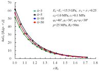

For M-C rock mass, Figure 6 shows the dimensionless displacement 4uGk/[R 0(p-σk )]=55.72 for k=5 and 4uG/[R 0(p-σk)]=56.68 for k=50 at the excavation surface when supporting pressure σ 0=0. The relative error of dimensionless displacement between k =5 and k=50 is 1.69%. For H-B rock mass, Figure 7 shows the dimensionless displacements are 4uGk/[ R0(p-σk )]=18.15 for k=5 and 4uGk/[ R0(p-σk )]=18.75 for k=50. And the relative error of dimensionless displacement between k=5 and k=50 is 3.31%. The tolerance is thought to be acceptable and k=50 is taken in the following analysis.
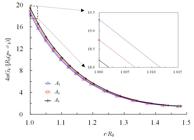
7.2. Consistency test of three compatibility conditions
There is a unique solution for the proposed problem. And the solutions of three compatibility conditions should theoretically converge to the unique solution when k is large enough. So, the consistency test of three kinds of compatibility conditions is performed. Also, the critical shear plastic strain η*=0.025 and k=50 is considered.
Figures 8 and 9 show the dimensionless displacements for M-C and H-B rock mass, respectively. As we can see, dimensionless displacements obtained from the three representative points are of the same distribution. The maximum relative errors occur at the excavation surface. The maximum errors of dimensionless displacement between represent point A1 and A3 are 4.28% and 6.11% for M-C and H-B rock mass, respectively. We can imagine that the relative error will decrease with the increase of k . When the number of post-failure regions is large enough, the results of three representative points would converge. In the following, representative point A 2 is chosen for the further analysis.

7.3. Validation for strain-softening rock mass
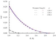
Several of critical shear plastic strains η* are considered for the stain-softening rock mass. The residual region, plastic region and displacement with different shear plastic strain is illustrated in Figures 10 - 15 . Figures 10 , 11 and 12 are for M-C strain-softening rock mass and Figures 13 , 14 and 15 for H-B strain-softening rock mass.


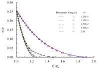
Elasto-perfectly-plastic model and elasto-brittle- plastic model are extreme cases of coupling strain-softening rock mass. When η*=0, the proposed model become the classic elasto-brittle-plastic model, and when η *→∞, it will change into the elasto-perfectly-plastic model.
For the M-C rock mass, the critical internal pressure σk =4.91MPa (σk/σ0=0.196). Figure 10 shows the dimensionless displacement with various internal supporting pressure, and Figures 11 and 12 show the softening radius Rk and residual radius R1 evolution as internal pressure decrease from critical value to zero. When η*=2, the softening radius Rk and dimensionless displacement (u/R 0)4Gk/(p-σk) of excavation surface reaches the smallest value. R k/R0=1.20 and (u/ R0)4Gk/(p-σ k)=3.93. When η*=1.25e-5, the softening radius Rk/R0 =1.88 and dimensionless displacement (u/R 0)4Gk/(p-σk)=126.24, the softening radius and radial displacement of excavation surface reach the maximum.
Figure 10 also shows that the dimensionless displacement overlaps with the elasto-brittle-plastic solution when η* takes the value of 1.25e-5 and that it overlaps with the elasto-perfectly-plastic solution when η* takes the value of 2.0. Figure 12 shows that there would be no residual region occurs when η* increase to a certain value.
For H-B rock mass, the critical internal pressure σk =6.45MPa (σk/σ0=0.258). The softening radius Rk, residual radius R 1 and cavity wall displacement change with the supporting pressure, which has the same trend as those for M-C rock mass.
The results shown in Figures 10 ~15 indicate that the proposed analytical method is in excellent agreement with the numerical method by Wang [ 3131 Wang SL, Yin SD, Wu ZJ. Strain-softening analysis of a spherical cavity. Int J Num Anal Met 2012; 36, 182-202. ].
7.4. Influence of elastic parameters in the post-failure region
The linear distribution form of elastic parameters is assumed, and ζ E=E1/Ek and ζμ=μ 1/μk are employed to denote the deterioration degree of Young’s modulus and Poisson’s ratio in the residual region. Restrictive condition Equations (33-35) show that the critical value of elastic parameters also related to its strength characters in the post-failure region. The smallest elastic parameters tend to nil because of the poor strength character. In this part, the influence of Young’s modulus and Poisson’s ratio on stress and displacement of surrounding rock mass are studied separately. That is to say, the deterioration coefficient of Young’s modulus is set to be 1 when Poisson’s ratio is studied, and vice versa. Besides of the condition of ζE=ζμ =1.0, another two sets of deteriorated elastic parameters ζE = ζμ=0.3 and 0.5 are employed to study its influence on stress and displacement. When case 3 are considered, the influence of elastic parameters on displacement and plastic radius are shown in Table 1 and Figures 16 ~19 .

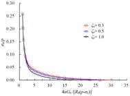

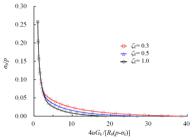
The results indicate that softening radius, residual radius and dimensionless displacement at r=R0 increase with the increasing deteriorated degree of Young’s modulus and Poisson’s ratio. In fact, the Poisson’s ratio of failure rock mass increases, which leads to a decreasing plastic radius and displacement. For the M-C rock mass, the residual radius, plastic radius and displacement at excavation surface increase by 8.33%, 2.37% and 96.47% when ζE decreases to 0.3, and that of 5.56%, 2.37% and 46.39% corresponds to ζ μ=0.3. For the H-B rock mass, R1 /R0, Rk/R 0 and (u0/R0 )4Gk/(p-σk ) increase by 9.02%, 4.08% and 105.01% when ζE decreases from 1.0 to 0.3. Meanwhile, while ζμ decreases from 1.0 to 0.3, R1/R 0, Rk/R0 and ( u0/R0)4Gk /(p-σk) increase by6.58%, 3.40% and 59.84%. Clearly, the influence of Young’s modulus and Poisson’s ratio affect the residual and plastic radius slightly with a percentage less than 10%. However, the displacement increases more than 45%, with a maximum value of 105%. Thus, the elastic parameters mainly enlarge the displacement of surrounding rock.
8. Conclusions
In this paper, analytical solutions for a spherical cavity problem subject to hydrostatic initial stresses in strain-softening M-C and H-B rock mass were proposed by simplifying the strain-softening rock mass as a multi-step brittle plastic spherical shell. Meanwhile, the deterioration process of elastic parameters (Young’s modulus and Poisson’s ratio) was also considered. The closed-form solutions for elasto-perfectly-plastic rock mass were firstly derived. Then, using the continuum conditions between adjacent shells, the compatibility equations for obtaining the shell radii were presented and they can be solved with a simple and efficient method. Meanwhile, the restrictive condition in the post-failure region was proposed theoretically considering the deteriorated limitation. Finally, the proposed solutions were validated with two sets of the strain-softening rock mass and the proposed analytical solution is in excellent agreement with the former study. The results also show the strain-softening solutions respectively converge to an elasto-perfectly-plastic solution and elasto-brittle-plastic solution when critical shear plastic strain is big enough and zero.
The influence of elastic parameters was also analyzed. The results show deteriorated Young’s modulus decrease residual radius, softening radius and displacement in the surrounding rock. The change of residual and softening radii is little, but the change of displacement is significant. However, increasing Poisson’s ratio has the opposite influence. Moreover, the restrictive conditions can be used to check whether the data from indoor and field tests are correct.
Acknowledgments
This project is supported by the National Basic Research 973 Program of China (2014CB046306), National Natural Science Foundation of China (51204168 and 51579239).
References
-
1Brown ET, Bray JW, Ladanyi B, Hoek E. Ground response curves for rock tunnels. J Geotech Geoenviron 1983;109, 15–39.
-
2Reed MB. Stresses and displacements around a cylindrical cavity in soft rock. IMA J App Math 1986; 36, 223–45.
-
3Ogawa T, Lo KY. Effects of dilatancy and yield criteria on displacements around tunnels. Can Geotech J, 1987; 24:100–13.
-
4Gates DJ, Strain softening around cavities in rock-like materials. Mech Mater 1990; 8, 309-331.
-
5Sharan SK. Elastic-brittle-plastic analysis of circular openings in Hoek-Brown media. Int J Rock Mech Min Sci 2003; 40, 817-24.
-
6Sharan SK. Analytical solutions for stresses and displacements around a circular opening in a generalized Hoek-Brown rock. Int J Rock Mech Min Sci 2008; 45,78-85.
-
7Park KH, Kim YJ. Analytical solution for a circular opening in an elastic-brittle-plastic rock. Int J Rock Mech Min Sci 2006; 43, 616-22.
-
8Yuan WB, Chen J. Analysis of plastic zone and loose zone around opening in softening rock mass. Journal of China Coal Society 1986; 3, 77-86.
-
9Jiang BS,Zhang Q,He YN, Han LJ. Elastioplastic analysis of cracked surrounding rocks in deep circular openings. Chinese Journal of Rock Mechanics and Engineering 2007; 26, 982–986.
-
10Yu HS. Cavity Expansion Methods in Geomechanics. Dordrecht: Kluwer, 2000.
-
11Wang Y. Ground response of circular tunnel in poorly consolidated rock. Journal of Geotechnical Engineering 1996; 122, 703-8.
-
12Carranza-Torres C, Fairhurst C The elasto-plastic response of underground excavations in rock masses that satisfy the Hoek–Brown failure criterion. Int J Rock Mech Min Sci 1999; 36,777–809.
-
13Alonso E, Alejano LR, Varas F, Fdez-Manin G, Carranza-Torres C. Ground response curves for rock masses exhibiting strain-softening behavior. Int J Numer Anal Met 2003; 27,1153-85.
-
14Bazant ZP. Instability, ductility, and size effect in strain-softening concrete. Journal of the Engineering Mechanics Division 1976; 102, 331-44.
-
15Park KH, Tontavanich B, Lee JG. A simple procedure for ground response curve of circular tunnel in elastic-strain softening rock masses. Tunn Undergr Sp Tech 2008; 23, 151-9.
-
16Lee YK, Pietruszczak S. A new numerical procedure for elasto-plastic analysis of a circular opening excavated in a strain-softening rock mass. Tunn Undergr Sp Tech 2008; 23, 588-99.
-
17Wang SL, Yin XT, Tang H, Ge XR. A new approach for analyzing circular tunnel in strain-softening rock masses. Int J Rock Mech Min Sci 2010; 1, 170-8.
-
18Wang SL, Zheng H, Li CG, Ge XR. A finite element implementation of strain-softening rock mass. Int J Rock Mech Min Sci 2011; 48, 67-76.
-
19Kulhawy FH. Stress deformation properties of rock and rock discontinuities. Eng Geol 1975; 9, 327-50.
-
20Brown ET, Bray JW, Santarelli FJ. Influence of stress-dependent elastic moduli on stresses and strains around axisymmetric boreholes. Rock Mech Rock Eng 1989; 22, 189 –203.
-
21Asef MR, Reddish DJ. The impact of confining stress on the rock mass deformation modulus. Geotechnique 2002; 52, 235-41.
-
22Verman M, Singh B, Viladkar MN, Jethwa JL. Effect of tunnel depth on modulus of deformation of rock mass. Rock Mech Rock Eng 1997; 30, 121-7.
-
23Zhang Q, Zhang CH, Jiang BS, Li N, Wang YC. Elastoplastic coupling solution of circular openings in strain-softening rock mass considering pressure-dependent effect. Int J Geomech, 2018; 18(1), 04017132
-
24Ewy RT, Cook NGW. Deformation and fracture around cylindrical openings in rock-I: Observations and analysis of deformations. Int J Rock Mech Min Sci 1990; 27, 387-407.
-
25Nawrocki PA, Dusseault MB. Modelling of damaged zones around openings using radius-dependent Young’s modulus. Rock Mech Rock Eng 1995; 28, 227-39.
-
26Liu RC, Li B, Jiang Y. Critical hydraulic gradient for nonlinear flow through rock fracture networks: the roles of aperture, surface roughness, and number of intersections. Adv Water Resour 2016, 88: 53-65.
-
27Liu RC, Jiang YJ, Li B, Wang X. A fractal model for characterizing fluid flow in fractured rock masses based on randomly distributed rock fracture networks. Comput Geotech 2015, 65: 45-55.
-
28Luo ZY, Zhu XR, Gong X. Expansion of spherical cavity of strain-softening materials with different elastic moduli of tension and compression. J Zhejiang Univ-sc A 2007; 8, 1380-7.
-
29Martin CD, Chandler NA. The progressive fracture of Lac du Bonnet granite. Int J Rock Mech Min Sci 1994; 31, 643-59.
-
30Zhang Q, Jiang BS, Wu XS, Zhang HQ, Han LJ. Elasto-plastic coupling analysis of circular openings in elasto-brittle-plastic rock mass. Theor Appl Fract Mec 2012; 60, 60-7.
-
31Wang SL, Yin SD, Wu ZJ. Strain-softening analysis of a spherical cavity. Int J Num Anal Met 2012; 36, 182-202.
Publication Dates
-
Publication in this collection
16 May 2018 -
Date of issue
2018
History
-
Received
14 Mar 2018 -
Reviewed
12 Apr 2018 -
Accepted
18 Apr 2018


