
Abstract
The main aim of this paper is to employ an extension of two-variable Refined Plate Theory (RPT2) to determine Sound Transmission Loss (STL) across laminated composite plate in contrast to external excitation. It should be noted that RPT2 known as a second type of Refined Plate Theory which includes the extension term in displacement field. To achieve this goal, firstly, the lateral displacements are expanded by considering three parts, including shear, bending and extension term to provide an analytical model based on two-variable Refined Plate Theory without considering the effect of the shear correction coefficient in governing equations. Secondly, vibro-acoustic analysis is administered by incorporating the laminated composite plate equation beside the acoustic wave equation, simultaneously. Consequently, the power transmission through the structure is specified due to a plane sound wave. Beside, in order to illustrate the accuracy of the present formulation (RPT2), the obtained STL is compared with those available in literature. However, the application of present study (RPT2) is clarified in the acoustical designs due to presenting more precise results in comparison with Classical Plate Theory. Eventually, the numerical results are achieved to determine the influences of various properties on STL.
Keywords
Sound Transmission Loss; Two Variable Refined Plate Theory; laminated composite Plate
1 INTRODUCTION
Laminated composite plates are extensively being employed in various technical applications due to high stiffness to weight ratio. Furthermore, the application of these structures in aerospace industries has been absorbed the researcher’s attention since last decades as a result of their light weights as well as their characteristics in noise and vibration control. Besides, the elastic wave propagation as well as interaction of sound waves in these structures is known as another serious major that should be identified. Likewise, when these structures are set in contrast to external fluid, the generation of the unwanted turbulence is unavoidable. However, this generated noise by transmitting into the cabin causes annoyance to the passengers and crew and also leads into structural fatigue. Accordingly, the inspection of the acoustic vibration which leads to interpretation of Sound Transmission Loss (STL) through these structures is brought forward.
Noise transmission, evaluated by Sound Transmission Loss (STL) through such structures, has been taken into account by many authors. Bhattacharya et al. (1971) Bhattacharya, M., Guy, R., Crocker, M., (1971). Coincidence effect with sound waves in a finite plate. Journal of sound and vibration 18: 157-169. , presented a theoretical model through the finite plate to determine STL. In this research work, two procedures were followed on the basis that in the first one a finite plate backed by a cavity was taken into account. On the other hand, in the second one a finite plate having no backing cavity was considered. In the following, Koval (1976) Koval, L.R., (1976). Effect of air flow, panel curvature, and internal pressurization on field‐incidence transmission loss. The Journal of the Acoustical Society of America 59: 1379-1385. proposed a theoretical model of STL through the single walled panel by considering the influences of panel curvature, external air flow and internal fuselage pressurization. Moreover, it was shown that mean flow as well as panel curvature are recognized as parameters that have a direct influence on STL. In an experimental and analytical model that suggested by Wu and Maestrello (1995) Wu, S.F., Maestrello, L., (1995). Responses of finite baffled plate to turbulent flow excitations. AIAA Journal 33: 13-19. a formulation for obtaining acoustics as well as dynamic response of the finite baffled plate impinged upon turbulent boundary layer excitation was discussed. However, Clark and Frampton (1996) Clark, R.L., Frampton, K.D., (1996). Sound transmission through an aeroelastic plate into an acoustic cavity. The Journal of the Acoustical Society of America 99: 2586-2603. calculated the STL through a convected fluid loaded plate employing Galerkin’s method to model the plate and cavity. On the other hand, the aerodynamic forces were clarified by using singular value decomposition method. Tang et al. (2006a Tang, H., Luo, C., Zhao, X., (2006a). Sound transmission behavior through a sandwiched electrorheological layer. Acta Materiae Compositae Sinica 23: 128-132. , 2006b Tang, H., Zhao, X.-p., Luo, C.-r., (2006b). Sonic responses of an electrorheological layer with one side of grating electrodes. Journal of Physics D: Applied Physics 39: 552. ) navigated their attention through a triple layered panel to determine STL. It is noteworthy that the structure was composed of two plastic plates with an ER mid layer. In the following, the STL of the lightweight all-metallic panels was achieved by Xin and Lu (2010) Xin, F., Lu, T., (2010). Analytical modeling of sound transmission across finite aeroelastic panels in convected fluids. The Journal of the Acoustical Society of America 128: 1097-1107. sandwiching corrugated cores as well as employing the space-harmonic method. It should be considered that two parallel panels are connected uniformly with distributed rotational and translational springs. Besides, an analytical model of STL proposed through finite as well as infinite aero elastic panels in convected fluids. It is essential to mention that the influence of mean flow on sound transmission was presented by three various condition, including existence of mean flow on radiating, incident and also the both sides. Then, the Classic Shell Theory was employed by Daneshjou et al. (2011) Daneshjou, K., Ramezani, H., Talebitooti, R., (2011). Wave transmission through laminated composite double-walled cylindrical shell lined with porous materials. Applied Mathematics and Mechanics 32: 701-718. to designate the STL of double-walled cylindrical shell subjected to porous core. Following the last work, the acoustic behavior of the panels subjected to air gap insulation was interpreted Arunkumar et al. (2016) Arunkumar, M., Pitchaimani, J., Gangadharan, K., Babu, M.L., (2016). Influence of nature of core on vibro acoustic behavior of sandwich aerospace structures. Aerospace Science and Technology 56: 155-167. . Koval (1980) Koval, L.R., (1980). Sound transmission into a laminated composite cylindrical shell. Journal of Sound and Vibration 71: 523-530. studied the transmission as well as the reflection at plane displacement discontinuity surface in second gradient solid. In this regard, another work by Vashishth and Sukhija (2015) Vashishth, A., Sukhija, H., (2015). Reflection and transmission of plane waves from fluid-piezothermoelastic solid interface. Applied Mathematics and Mechanics 36: 11-36. was suggested across the reflection and transmission of plane wave from a fluid-piezothermoelastic solid interface. Consequently, Tang et al. (1996a Tang, Y.Y., Robinson, J.H., Silcox, R.J., (1996a). Sound transmission through a cylindrical sandwich shell with honeycomb core, 34th AIAA aerospace science meeting and exhibit, pp: 877-886. , 1996c Tang, Y.Y., Silcox, R.J., Robinson, J.H., (1996c). Sound transmission through two concentric cylindrical sandwich shells. ) considered honeycomb core as an intermediate layer to enhance the amount of STL. Moreover, the STL was calculated in Tang et al.(1996b) Tang, Y.Y., Silcox, R.J., Robinson, J.H., (1996b). Sound transmission through cylindrical shell structures excited by boundary layer pressure fluctuations. NASA Rep 96: 1760. work through the cylindrical shell sandwiching a layer impinged upon an exterior turbulent boundary layer. As it’s obvious, the importance of using laminated composite shell is unavoidable. For this reason, Daneshjou et al. (2007 Daneshjou, K., Nouri, A., Talebitooti, R., (2007). Sound transmission through laminated composite cylindrical shells using analytical model. Archive of Applied mechanics 77: 363-379. , 2009 Daneshjou, K., Nouri, A., Talebitooti, R., (2009). Analytical model of sound transmission through orthotropic cylindrical shells with subsonic external flow. Aerospace Science and Technology 13: 18-26. ) absorbed their regard to determine STL of the laminated composite as well as orthotropic circular cylindrical shells. Just recently, an analytical model of double-walled sandwich shells was offered by Liu and He (2016) Liu, Y., He, C., (2016). Analytical modelling of acoustic transmission across double-wall sandwich shells: Effect of an air gap flow. Composite Structures 136: 149-161. to illustrate the influence of air gap flow on STL by employing the Love’s theory to obtain the shell motion. It should be noted that they considered elasticity theory to determine the motion of the isotropic thick polymer core. However, Talebitooti and Khameneh (2017) Talebitooti, R., Khameneh, A.C., (2017). Wave propagation across double-walled laminated composite cylindrical shells along with air-gap using three-dimensional theory. Composite Structures. , a complete model of power transmission on the double-walled laminated composite cylindrical shells along with air-gap was proposed applying three-dimensional equations of anisotropic elasticity. In the following, Talebitooti et al. (2017a) Talebitooti, R., Gohari, H. D., Zarastvand, M. R. (2017a). Multi objective optimization of sound transmission across laminated composite cylindrical shell lined with porous core investigating Non-dominated Sorting Genetic Algorithm. Aerospace Science and Technology. employed the Genetic Algorithm to optimize the sound transmission of the structure subjected to porous material. Besides, Talebitooti et al. (2016) Talebitooti, R., Zarastvand, M., Gheibi, M., (2016). Acoustic transmission through laminated composite cylindrical shell employing Third order Shear Deformation Theory in the presence of subsonic flow. Composite Structures 157: 95-110. presented an analytical model across the specifications of the laminated composite cylindrical shell based on Third-order Shear Deformation Theory in the existence of external mean flow. Likewise, the displacements are derived as a cubic order of the thickness coordinate. Consequently, the equations of vibration related to cylindrical shell are combined with acoustic wave equation to clarify sound transmission into such structure. As another consequence, the vibroacoustic behavior of the laminated composite doubly curved shell was analyzed by Talebitooti et al. (2017b) Talebitooti, R., Zarastvand, M. R., Gohari, H. D. (2017b). Investigation of power transmission across laminated composite doubly curved shell in the presence of external flow considering shear deformation shallow shell theory. Journal of Vibration and Control, 1077546317727655. in another paper based on considering Shear Deformation Shallow Shell Theory. In another work, Talebitooti et al. (2018a Talebitooti, R., Zarastvand, (2018a). Vibroacoustic behavior of orthotropic aerospace composite structure in the subsonic flow considering the Third order Shear Deformation Theory Aerospace Science and Technology,75, 227-236. , b Talebitooti, R., Zarastvand, (2018b). The effect of nature of porous material on diffuse field acoustic transmission of the sandwich aerospace composite doubly curved shell. Aerospace Science and Technology,75, 227-236. ), Third order Shear Deformation Theory was employed through sound transmission of the orthotropic doubly curved composite shell. They also inspected the influence of porous core on acoustic transmission of the doubly curved composite shell.
Literature clearly demonstrates that, although the STL on the variety of laminated theories has been presented and discussed, there is no investigation of STL through the plate employing an extension of two variables Refined plate theory (RPT2), so far. Earlier, to analyze the equation of motion of the plate, Classical thin Laminated Plate Theory was taken into account in which transverse shear and rotation effects are completely ignored. However, it should be noted that since the effect of transvers shear especially for thick plate become important, then, First-order Shear Deformation Theory (FSDT) is used to fulfill this end. Likewise, FSDT was developed based on stress approach for the first time by Reissner (1944 Reissner, E., (1944). On the theory of bending of elastic plates. Journal of mathematics and physics 23: 184-191. , 1945 Reissner, E., (1945). The effect of transverse shear deformation on the bending of elastic plates. ) with inserting the effect of transvers shear in its equations. Later, Reissner’s theory was extended by Mindlin (1951) Mindlin, R.D., (1951). Influence of rotary inertia and shear on flexural motions of isotropic elastic plates. which is well-known as Mindlin’s theory based on displacement approach. It is necessary to mention that FSDT was proposed by entering shear correction coefficient as well as regarding constant transvers shear stress through the thickness of the plate. Finally, it is noteworthy that the theory which is followed in this paper is well-known as RPT2, without entering shear correction factor (which is recognized as interesting feature of this theory) in its equations to interpret the behavior of STL in the existence of airflow. Besides, in the present formulation (RPT2) the effects of shear, extension and bending are taken into account in its transverse displacement while in other theories including FSDT as well as HSDT are being neglected. However, the importance of employing the RPT2 in comparison with other theories including FSDT and HSDT is clarified in a work done by Kim et al. (2009) Kim, S.-E., Thai, H.-T., Lee, J., (2009). A two variable refined plate theory for laminated composite plates. Composite Structures 89: 197-205. as a result of demonstrating the accurate results. Furthermore, this procedure is applicable for Naviour closed form solution in the free vibration state. As another aspect, although the present study (RPT2) does not have the complicated process such HSDT, but the obtained result present the accuracy of the current formulation or sometimes the better results could be observed. It is not also refused to note that the present formulation appears much more effective in transverse deflection as well as buckling in comparison to HSDT, as a result of demonstrating accurate results. Consequently, the obtained STL from present study (RPT2) is compared with those of literature to demonstrate the validity of the present results in entire range of frequency. Furthermore, in numerical result section the effects of various properties on STL are presented and discussed.
2 System description
As depicted in Figure 1 , a laminated composite flat plate with mass density of the shell and thickness h is considered impinged upon two angles , in which denotes the angle between wave and horizontal plane and is specified as the clockwise angle from the projection of wave on the horizontal surface to the direction. It should be noted that the plate is assumed to be infinitely long from two sides with an external airflow in the exterior fluid medium. To provide the acoustic situation of the problem the interior of the plate is considered to be totally absorbing. Furthermore, the density and speed of the sound in the acoustic media are illustrated by and in which the subscripts and are associated to the incident and transmitted sides, respectively.

3 Refined plate theory for laminated composite plates:
3.1 Fundamental presumptions
Since the extended two variables Refined Plate Theory (RPT2) is employed in this paper, some assumptions are taken into account based on those described in ( Kim et al., 2009 Kim, S.-E., Thai, H.-T., Lee, J., (2009). A two variable refined plate theory for laminated composite plates. Composite Structures 89: 197-205. ). Accordingly, it is essential to note that in this theory the lateral displacement composed of three components: shear section , bending component and extension component . As another aspect, these three components are only considered to be a function of general coordinates and time as follows:
Note that for being consensus, it is refused to bring forward the other assumptions related to this theory in this paper, again.
3.2 Kinematic relation
The displacement fields of the RPT2 are presented in what follows form ( Kim et al., 2009 Kim, S.-E., Thai, H.-T., Lee, J., (2009). A two variable refined plate theory for laminated composite plates. Composite Structures 89: 197-205. ):
The following stress-strain relations for each lamina of the laminated composite shell are also recognized as follows:
Where the detailed description of the transformed stiffness coefficients could be found in ( Qatu, 2004 Qatu, M.S., (2004). Vibration of laminated shells and plates. Elsevier. ). Furthermore, the parameter presents the number of layers. As another consequence, the stresses in Eq. (5) are arranged as below:
As obviously defined, the Eq. (6) includes some terms in the following forms:
Consequently, it is attempted to integrate the stresses over the shell thickness, to present the forces and moments as below:
3.3 Equations of motion
The differential equation of motion of the RPT2 related to laminated composite plate can be derived by using Hamilton’s principle, as follows:
4. Boundary conditions
On the incident side as well as transmitted side of plate surfaces, the acceleration of the fluid particle through the acoustic media in the normal direction has to be equal to the normal acceleration of the plate. As a result, following equations are considered as ( Howe, 1998 Howe, M.S., (1998). Acoustics of fluid-structure interactions. Cambridge university press. ; Shojaeefard et al., 2014b Shojaeefard, M.H., Talebitooti, R., Ahmadi, R., Ranjbar, B., (2014b). A study on acoustic behavior of poroelastic media bonded between laminated composite panels. Latin American Journal of Solids and Structures 11: 2379-2407. ):
In above equations, , and demonstrate three acoustic pressures related to the incident, transmitted and reflected waves, respectively.
5. Vibro-acoustic Solution
As demonstrated in Figure 1 , three acoustic pressures are diagnosed as following:
In above equations, describes amplitude of the incident wave, displays the wave number in the external moving medium, devotes the angular frequency, represents the wave number in the direction and denotes the wave number in the direction as below:
As it’s obvious, the incident traveling wave carry out the traveling wave in the plate, the wave numbers in the direction should adapt throughout the system, so:
The displacement terms of the mid surface are presented as below:
By substituting Eqs. (15) - (17) and (20) into shell equation (12) and also taking account Eqs. (13 , 14 )))))) simultaneously, the solutions can be provided as the ratio of the pressure amplitude of the incident wave. Finally, the result of this superposition can be represented in the matrix form as below:
with
In Eq. (21) , L describes the coefficient matrix and F denotes the vector showing the acoustic forces. The detailed explanations of these constants could be found in the Appendix A Appendix A The detailed descriptions of the coefficient matrix [L] as well as vector of acoustic force [F] are presented as below: L 11 = A 11 k p x 2 + A 66 k p y 2 + 2 A 16 k p x k p y − I 0 ω 2 L 12 = A 16 k p x 2 + A 26 k p y 2 + A 12 k p x k p y + A 66 k p x k p y L 13 = B 11 k p x 3 + B 26 k p y 3 + B 12 k p x k p y 2 + 3 B 16 k p x 2 k p y + 2 B 66 k p x k p y 2 L 14 = B s 11 k p x 3 + B s 26 k p y 3 + B s 12 k p x k p y 2 + 3 B s 16 k p x 2 k p y + 2 B s 66 k p x k p y 2 L 21 = A 16 k p x 2 + A 26 k p y 2 + A 12 k p x k p y + A 66 k p x k p y L 22 = A 66 k p x 2 + 2 A 26 k p x k p y + A 22 k p y 2 − I 0 ω 2 L 23 = B 16 k p x 3 + B 22 k p y 3 + B 12 k p x 2 k p y + 3 B 26 k p x k p y 2 + 2 B 66 k p x 2 k p y L 24 = B 16 s k p x 3 + B 22 s k p y 3 + B 12 s k p x 2 k p y + 3 B 26 s k p x k p y 2 + 2 B 66 s k p x 2 k p y L 31 = B 11 k p x 3 + B 26 k p y 3 + B 12 k p x k p y 2 + 3 B 16 k p x 2 k p y + 2 B 66 k p x k p y 2 L 32 = B 16 k p x 3 + B 22 k p y 3 + B 12 k p x 2 k p y + 3 B 26 k p x k p y 2 + 2 B 66 k p x 2 k p y L 33 = D 11 k p x 4 + D 22 k p y 4 + 2 D 12 k p x 2 k p y 2 + 4 D 66 k p x 2 k p y 2 + 4 D 16 k p x 3 k p y + 4 D 26 k p x k p y 3 − I 0 ω 2 − I 2 ( k p x 2 ω 2 + k p y 2 ω 2 ) L 34 = D 11 s k p x 4 + D 22 s k p y 4 + 2 D 12 s k p x 2 k p y 2 + 4 D 66 s k p x 2 k p y 2 + 4 D 16 s k p x 3 k p y + 4 D 26 s k p x k p y 3 − I o ω 2 L 35 = − I o ω 2 L 36 = − 1 L 37 = − 1 L 41 = B s 11 k p x 3 + B s 26 k p y 3 + B s 12 k p x k p y 2 + 3 B s 16 k p x 2 k p y + 2 B s 66 k p x k p y 2 L 42 = B 16 s k p x 3 + B 22 s k p y 3 + B 12 s k p x 2 k p y + 3 B 26 s k p x k p y 2 + 2 B 66 s k p x 2 k p y L 43 = D 11 s k p x 4 + D 22 s k p y 4 + 2 D 12 s k p x 2 k p y 2 + 4 D 66 s k p x 2 k p y 2 + 4 D 16 s k p x 3 k p y + 4 D 26 s k p x k p y 3 − I o ω 2 L 44 = A 55 s k p x 2 + A 44 s k p y 2 + H 11 s k p x 4 + H 22 s k p y 4 + 2 H 12 S k p x 2 k p y 2 + 4 H 66 S k p x 2 k p y 2 + 2 A 45 s k p x k p y + 4 H 16 s k p x 3 k p y + 4 H 26 s k p x k p y 3 − I 0 ω 2 − I 2 84 ( k p x 2 ω 2 + k p y 2 ω 2 ) L 45 = A 55 a k p x 2 + 2 A 45 a k p x k p y + A 44 a k p y 2 − I 0 ω 2 L 46 = − 1 L 47 = 1 L 53 = − I o ω 2 L 54 = A 55 a k p x 2 + 2 A 45 a k p x k p y + A 44 a k p y 2 − I 0 ω 2 L 55 = A 55 k p x 2 + 2 A 45 k p x k p y + A 44 k p y 2 − I 0 ω 2 L 56 = − 1 L 57 = 1 L 63 = − ( ρ 1 ω 2 + v x k p x 2 ) L 64 = − ( ρ 1 ω 2 + v x k p x 2 ) L 65 = − ( ρ 1 ω 2 + v x k p x 2 ) L 66 = k 1 z L 73 = − ( ρ 2 ω 2 ) L 74 = − ( ρ 2 ω 2 ) L 75 = − ( ρ 2 ω 2 ) L 77 = − k 2 z F 31 = P 0 i F 41 = P 0 i F 51 = P 0 i F 61 = k 1 z P 0 i .
6. Sound Transmission Loss
The power transmission coefficient can be obtained as a ratio of transmitted power and the incident power as follows ( Zhou et al., 2013 Zhou, J., Bhaskar, A., Zhang, X., (2013). Sound transmission through a double-panel construction lined with poroelastic material in the presence of mean flow. Journal of Sound and Vibration 332: 3724-3734. ):
Finally, the STL in the logarithmic scale can be prepared as below ( Shojaeefard et al., 2014a Shojaeefard, M.H., Talebitooti, R., Ahmadi, R., Gheibi, M.R., (2014a). Sound transmission across orthotropic cylindrical shells using third-order shear deformation theory. Latin American Journal of Solids and Structures 11: 2039-2072. ):
7. Coincidence frequency
In this section, it is identified to illustrate one important frequency and its corresponding regions before obtaining STL with respect to frequency.
Since the laminated composite plate is excited acoustically, the coincidence frequency is emerged as a result of the fact that the wavelength of the forced bending wave is equal to the wavelength of the free bending wave. As discussed in ( Zhou et al., 2013 Zhou, J., Bhaskar, A., Zhang, X., (2013). Sound transmission through a double-panel construction lined with poroelastic material in the presence of mean flow. Journal of Sound and Vibration 332: 3724-3734. ), the coincidence frequency of an isotropic plate is presented as:
In Eq. (25) , represents the modulus of elasticity, denotes the density, devotes the Poisson’s ratio and is related to the wall thickness, respectively.
8. Numerical Results
The two variables Refined Plate Theory expanded here, can be employed efficiently in the substantial design step of the plate Vibro-acoustic systems. Due to the complexity of the solution presented as well as the behavior of the equation obtained, some numerical cases are investigated. Moreover, each layer of laminated composite flat plate is made of Graphite/Epoxy which the fiber orientation angles are arranged in a pattern (see Figure 1 ). The acoustic properties of the fluids are listed in Table 1 .
At the start of this section, it is recognized to verify the validity of the present formulation (RPT2) with those of literature for the special case of isotropic shell; then, the obtained results have been compared with those of Xin and Lu (2010) Xin, F., Lu, T., (2010). Analytical modeling of sound transmission across finite aeroelastic panels in convected fluids. The Journal of the Acoustical Society of America 128: 1097-1107. and Roussos (1984) Roussos, L.A., (1984). Noise transmission loss of a rectangular plate in an infinite baffle. The Journal of the Acoustical Society of America 75: S2-S3. . It should be noted that the structural properties used in these comparisons are listed in Table 1 .
Fig. 2 compares the obtained STL from present result (RPT2) with those offered by Xin and Lu (2010) Xin, F., Lu, T., (2010). Analytical modeling of sound transmission across finite aeroelastic panels in convected fluids. The Journal of the Acoustical Society of America 128: 1097-1107. . Likewise, it is easily seen that although the two curves are completely corporated to each other in the frequency region below 86 Hz but the offered results by Xin and Lu present the higher level of STL over this frequency. In fact, this trend is generated due to employing RPT2 in the present study.
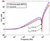
STL comparison between present study(RPT2) and Xin and Lu (2010) Xin, F., Lu, T., (2010). Analytical modeling of sound transmission across finite aeroelastic panels in convected fluids. The Journal of the Acoustical Society of America 128: 1097-1107. .
As another consequence, the numerical result of this comparison is set to Table 2 . In addition, as illustrated in Fig. 3 and Table 3 , the present results are also compared with those of Roussos by taking account the same data as ( Roussos, 1984 Roussos, L.A., (1984). Noise transmission loss of a rectangular plate in an infinite baffle. The Journal of the Acoustical Society of America 75: S2-S3. ). As it is obvious, no difference could be considered in the coincidence frequency between two theories which is set to 20250 Hz. Although, Roussos’s model gives a good validity to our results and the two theories are exactly corroborated to each other in high frequency region, a little difference is brought up in frequency region below 2000 Hz. As another consequence, although the theory used by Roussos was the same with Xin and Lu, it is essential to mention the fact that the thickness of the plate which was considered by Roussos was about three times fewer than Xin and Lu which caused the fewer amounts of discrepancies in entire range of frequency. These two comparisons indicate the superiority of RPT2 in contrast with CST particularly in thick plates.
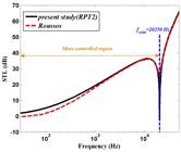
STL comparison of present study (RPT2) and Roussos (1984) Roussos, L.A., (1984). Noise transmission loss of a rectangular plate in an infinite baffle. The Journal of the Acoustical Society of America 75: S2-S3. .
In addition, it is necessary to mention that the obtained coincidence frequency from current problem (RPT2) is adopted with those calculated from Eq. (25) in two validation. Furthermore, as illustrated in Fig. 3 , the region in low frequency dropped below the coincidence frequency known as mass-controlled region. On the other hand, the stiffness-controlled zone is fallen over this frequency ( Renji et al., 1997 Renji, K., Nair, P., Narayanan, S., (1997). Critical and coincidence frequencies of flat panels. Journal of Sound and Vibration 205: 19-32. ).
As shown in Fig. 4 the influence of various external Mach number of the upstream flow on STL is discussed. The inspection of this figure demonstrates that variation of the Mach number has a direct effect on STL in mass-controlled region. In fact, upper Mach number makes STL to be enhanced in this region. It is noteworthy that the coincidence frequency shifts forward in this case. As another consequence, the STL of the laminated composite plate by variation of this parameter behaves in opposite way particularly in stiffness - controlled region.

Figure 5 demonstrates the effects of various deviation angles on STL in the absence of airflow (it can be achieved by setting ). The inspection of this figure clarifies the fact that the variation of this angle does not have any effect on STL in low frequency region. But at high frequency zone, increasing this angle leads to decrease STL because of reducing the stiffness in the wave propagation direction. Moreover, the effect of existing external mean flow is emerged in Fig. 6 . According to this figure, the influence of presence of external mean flow (Mach number of the upstream flow is considered 0.4) on STL by variation of this angle is unavoidable. In fact, the STL is significantly enhanced with increasing the angles. However, in mass-controlled region, it behaves in opposite way.

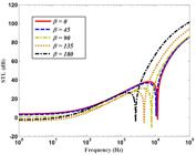
STL provided for a ten-layered composite plate with respect to various angles in the presence of air flow.
As illustrated in Fig. 7 , the effects of the various thicknesses on transverse displacement with respect to different frequencies are investigated by considering that the amplitude of the incident wave is assumed to be . It should be noted that this amplitude is recognized as the maximum sound pressure in industries ( Bies et al., 1996 Bies, D.H., Hansen, C.H., Campbell, R.H., (1996). Engineering noise control. The Journal of the Acoustical Society of America 100: 1279-1279. ; Ziobroski and Powers, 2005 Ziobroski, D., Powers, C., (2005). Acoustic Terms, Definitions and General Information. General Electric Company, GER-4248 (06/05). ). The present results apparent that, the variation of the frequency has an opposite effect on transverse displacement. However, increasing the frequency result in reducing the transverse displacements. Moreover,

Transverse displacement of the ten-layered composite plate with respect to various frequencies.
inspection of the figure demonstrates some points with specified thicknesses, in which the resonance is occurred with respect to their frequency. It is noteworthy that by increasing frequency the locations of these points shift downward. As another consequence, Fig. 8 is composed of some sub-figures to present the STL comparison of the ten-layered composite plate with a certain thickness versus to frequency. Note that these thicknesses are recognized as the thickness in which the transverse displacement is encountered with the structural resonance in the specified frequency (see Fig. 7 ). Besides, note that these sub-figures present the accuracy of present formulation as a result of the fact that the minimum of STL associated to each configuration is settled exactly in the definite frequency that was previously predicted in Fig. 7 .

STL comparison of the laminated composite plate with respect to resonance frequency in the definite thickness.
The effects of various orthotropic materials on STL of the ten-layered composite plate are illustrated in Fig. 9 . It should be noted that with changing the material, no significant influence could be observed on STL approximately below 110 Hz. However, the discrepancies are gradually brought up above this frequency. Consequently, the Glass/Epoxy as a result of higher density appears much more effective rather than other material, particularly in mass-controlled region. In high frequency range, the STL of the Graphite/Epoxy is upper than other material due to its highest stiffness in axial direction; In fact, the plane sound waves are propagated in this orientation. As another aspect, the clockwise angle from the projection of wave on the horizontal surface to the direction ( ) is set to zero.

Figure 10 demonstrates the effects of different angles of incidence on STL. As clearly defined in this figure, the STL value of the laminated composite plate is sensitive to variation of this parameter in mass-controlled region. In fact, with increasing this parameter, the STL is enhanced, as a result of the fact that the coincidence frequency shifts forward. However, in high frequency range, the trend is against the mass-controlled region.

STL provided for a ten-layered composite plate with respect to various angles of incidence.
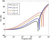
The effects of various densities on STL are investigated in Fig. 11 . As it is obvious, increasing the density of the ten-layered composite plate has a direct influence on STL in mass-controlled region due to increasing the mass of the plate. As another consequence, the coincidence frequency shifts upward in this case.
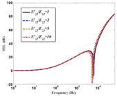
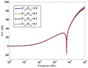
According to Figures 12 and 13 , the influence of different mechanical properties of material on STL of a ten-layered composite plate is discussed. As displayed in Fig. 12 , by increasing the stiffness of composite lamina in fiber direction , the STL is enhanced at high frequency domain. Note that the coincidence frequency behaves in opposite way in such a case. Additionally, the effect of increasing the stiffness on STL is emerged in Fig. 13 . As it is obvious, the STL of the laminated composite plate is enhanced, because of increasing this parameter particularly in stiffness-controlled region. It is noteworthy that, the rate of changing the stiffness in axial direction on STL is more desirable.

Investigation of various stiffness’s in axial direction on STL of the ten-layered composite plate.
As indicated in Fig. 14 , by variation the ply orientation of the laminated composite plate, no considerable change is appeared at low frequency region below 2700 Hz. On the other hand, the effect of zero degree plies in comparison with 90 degree plies and 45 degree plies are clarified in high frequency region. As another consequence, in comparison of two laminated which composed of 0 and 90 degree plies, each of them that contain 0 degree plies in the furthest layer present the desirable STL. As another aspect, the main goal from comparison between STL results obtained from and other patterns reveals the fact that although by using the 45 degree plies no considerable improvement on STL could be observed, it is not avoided to note that when the importance of bearing shear loads in such structures become significance, these 45 degree plies are arranged in ply orientation to fulfill this end.

The effects of various shear moduli on STL of the ten-layered composite plate are investigated in Figures 15 and 16 . Inspection of the results presents the fact that with increasing this shear stiffness, the STL is enhanced in higher frequency zone. But it is noteworthy that no significance changes could be observed by variation of this parameter in low frequency region.

In order to show the influence of varying the number of layers on STL curve, the Figure 17 is presented. As it is obvious, the STL of the current structure is sensitive to variation this parameter. In description the fact of this behavior should be noted that since increasing the number of the layer leads to enhancing the shell thickness, therefore this trend would be predicted as a result of increasing the shell stiffness and mass simultaneously. Accordingly, although the coincidence frequency shifts backward in this case, but the STL of the structure is enhanced in entire range of frequency. Likewise, it could be concluded that increasing the number of the layer is recognized as another factor in improving the sound insulation property of the laminated composite plate.

9. Conclusion
As obviously defined, the STL problem has been investigated by many authors across the structure based on employing various theories. Likewise, the inspection of the last literature shows that Classical thin Laminated Plate Theory has been taken in to account in which transverse shear and rotation effects are completely ignored. However, by thickening the structure First-order Shear Deformation Theory (FSDT) was employed which composed of the effects of shear correction coefficient factor and transvers shear stress across the thickness of the structure. Moreover, some other authors employed Mindlin’s theory obtain their corresponding results based on displacement approach. Therefore in the following of the last works, the present formulation based on RPT2 is recognized without entering shear correction factor (which is recognized as interesting feature of this theory) in its equations to interpret the behavior of STL in the existence of airflow. As another consequence, this theory considers the effects of shear, extension and bending in its transverse displacement while in other theories are being neglected. Besides, although the employed method does not have the complicated process of higher order theories but it is able to present the accurate results. It was also shown that the coincidence frequency of the laminated composite plate is sensitive to variation of Mach number as well as incident angle so that by increasing these parameters, it shifts forward. This is while, the STL ascends in mass-controlled region and descents in stiffness-controlled zone. However, increasing the stiffness in axial and tangential directions was recognized as another factor in increasing the sound insulation properties of these structures. It is noteworthy that the rate of the STL improvement by increasing the stiffness in axial direction is more remarkable. In this regards, the shear modules was appeared to be effective in improving the behavior of STL particularly at high frequency zone. At the end, it is not refused to mention that increasing the number of layer is recognized as another factor in improving the sound insulation property of the laminated composite plate.
Appendix A
The detailed descriptions of the coefficient matrix [L] as well as vector of acoustic force [F] are presented as below:
References
- Arunkumar, M., Pitchaimani, J., Gangadharan, K., Babu, M.L., (2016). Influence of nature of core on vibro acoustic behavior of sandwich aerospace structures. Aerospace Science and Technology 56: 155-167.
- Bhattacharya, M., Guy, R., Crocker, M., (1971). Coincidence effect with sound waves in a finite plate. Journal of sound and vibration 18: 157-169.
- Bies, D.H., Hansen, C.H., Campbell, R.H., (1996). Engineering noise control. The Journal of the Acoustical Society of America 100: 1279-1279.
- Clark, R.L., Frampton, K.D., (1996). Sound transmission through an aeroelastic plate into an acoustic cavity. The Journal of the Acoustical Society of America 99: 2586-2603.
- Daneshjou, K., Nouri, A., Talebitooti, R., (2007). Sound transmission through laminated composite cylindrical shells using analytical model. Archive of Applied mechanics 77: 363-379.
- Daneshjou, K., Nouri, A., Talebitooti, R., (2009). Analytical model of sound transmission through orthotropic cylindrical shells with subsonic external flow. Aerospace Science and Technology 13: 18-26.
- Daneshjou, K., Ramezani, H., Talebitooti, R., (2011). Wave transmission through laminated composite double-walled cylindrical shell lined with porous materials. Applied Mathematics and Mechanics 32: 701-718.
- Howe, M.S., (1998). Acoustics of fluid-structure interactions. Cambridge university press.
- Kim, S.-E., Thai, H.-T., Lee, J., (2009). A two variable refined plate theory for laminated composite plates. Composite Structures 89: 197-205.
- Koval, L.R., (1976). Effect of air flow, panel curvature, and internal pressurization on field‐incidence transmission loss. The Journal of the Acoustical Society of America 59: 1379-1385.
- Koval, L.R., (1980). Sound transmission into a laminated composite cylindrical shell. Journal of Sound and Vibration 71: 523-530.
- Liu, Y., He, C., (2016). Analytical modelling of acoustic transmission across double-wall sandwich shells: Effect of an air gap flow. Composite Structures 136: 149-161.
- Mindlin, R.D., (1951). Influence of rotary inertia and shear on flexural motions of isotropic elastic plates.
- Qatu, M.S., (2004). Vibration of laminated shells and plates. Elsevier.
- Reissner, E., (1944). On the theory of bending of elastic plates. Journal of mathematics and physics 23: 184-191.
- Reissner, E., (1945). The effect of transverse shear deformation on the bending of elastic plates.
- Renji, K., Nair, P., Narayanan, S., (1997). Critical and coincidence frequencies of flat panels. Journal of Sound and Vibration 205: 19-32.
- Roussos, L.A., (1984). Noise transmission loss of a rectangular plate in an infinite baffle. The Journal of the Acoustical Society of America 75: S2-S3.
- Shojaeefard, M.H., Talebitooti, R., Ahmadi, R., Gheibi, M.R., (2014a). Sound transmission across orthotropic cylindrical shells using third-order shear deformation theory. Latin American Journal of Solids and Structures 11: 2039-2072.
- Shojaeefard, M.H., Talebitooti, R., Ahmadi, R., Ranjbar, B., (2014b). A study on acoustic behavior of poroelastic media bonded between laminated composite panels. Latin American Journal of Solids and Structures 11: 2379-2407.
- Talebitooti, R., Khameneh, A.C., (2017). Wave propagation across double-walled laminated composite cylindrical shells along with air-gap using three-dimensional theory. Composite Structures.
- Talebitooti, R., Gohari, H. D., Zarastvand, M. R. (2017a). Multi objective optimization of sound transmission across laminated composite cylindrical shell lined with porous core investigating Non-dominated Sorting Genetic Algorithm. Aerospace Science and Technology.
- Talebitooti, R., Zarastvand, M., Gheibi, M., (2016). Acoustic transmission through laminated composite cylindrical shell employing Third order Shear Deformation Theory in the presence of subsonic flow. Composite Structures 157: 95-110.
- Talebitooti, R., Zarastvand, M. R., Gohari, H. D. (2017b). Investigation of power transmission across laminated composite doubly curved shell in the presence of external flow considering shear deformation shallow shell theory. Journal of Vibration and Control, 1077546317727655.
- Talebitooti, R., Zarastvand, (2018a). Vibroacoustic behavior of orthotropic aerospace composite structure in the subsonic flow considering the Third order Shear Deformation Theory Aerospace Science and Technology,75, 227-236.
- Talebitooti, R., Zarastvand, (2018b). The effect of nature of porous material on diffuse field acoustic transmission of the sandwich aerospace composite doubly curved shell. Aerospace Science and Technology,75, 227-236.
- Tang, H., Luo, C., Zhao, X., (2006a). Sound transmission behavior through a sandwiched electrorheological layer. Acta Materiae Compositae Sinica 23: 128-132.
- Tang, H., Zhao, X.-p., Luo, C.-r., (2006b). Sonic responses of an electrorheological layer with one side of grating electrodes. Journal of Physics D: Applied Physics 39: 552.
- Tang, Y.Y., Robinson, J.H., Silcox, R.J., (1996a). Sound transmission through a cylindrical sandwich shell with honeycomb core, 34th AIAA aerospace science meeting and exhibit, pp: 877-886.
- Tang, Y.Y., Silcox, R.J., Robinson, J.H., (1996b). Sound transmission through cylindrical shell structures excited by boundary layer pressure fluctuations. NASA Rep 96: 1760.
- Tang, Y.Y., Silcox, R.J., Robinson, J.H., (1996c). Sound transmission through two concentric cylindrical sandwich shells.
- Vashishth, A., Sukhija, H., (2015). Reflection and transmission of plane waves from fluid-piezothermoelastic solid interface. Applied Mathematics and Mechanics 36: 11-36.
- Wu, S.F., Maestrello, L., (1995). Responses of finite baffled plate to turbulent flow excitations. AIAA Journal 33: 13-19.
- Xin, F., Lu, T., (2010). Analytical modeling of sound transmission across finite aeroelastic panels in convected fluids. The Journal of the Acoustical Society of America 128: 1097-1107.
- Zhou, J., Bhaskar, A., Zhang, X., (2013). Sound transmission through a double-panel construction lined with poroelastic material in the presence of mean flow. Journal of Sound and Vibration 332: 3724-3734.
- Ziobroski, D., Powers, C., (2005). Acoustic Terms, Definitions and General Information. General Electric Company, GER-4248 (06/05).
Publication Dates
-
Publication in this collection
14 June 2018 -
Date of issue
2018
History
-
Received
03 Aug 2017 -
Reviewed
06 Nov 2017 -
Accepted
16 Nov 2017


