
Abstract
The international highways within the city limits of Istanbul are used to transit more than 15 million trucks and other heavy good vehicles per year. According to the statistics, the number of single truck run of the road accidents is in the rise. Recent accidents on bridges showed that currently used bridge rails specified by Istanbul Metropolitan Municipality (IMM) lack the required design criteria to safely contain and redirect heavy vehicles. The objective of this study is therefore design, analyze and test a new high containment level (HCL) bridge rail to be used on bridges on high risk locations, within the city limits of Istanbul. After the development and simulation phases, the bridge rail is subjected to full-scale crash testing in accordance with European Standard EN1317 to conclusively prove its adequacy. This study is of importance since the barrier is the first nationally developed high containment level bridge rail in Turkey. The bridge rail, YIM04 is currently in use on several bridge decks in Istanbul.
Keywords
Bridge Rail; Transportation Safety; Heavy Vehicle; Crash Test; Istanbul; EN1317; YIM04
1 Introduction
City of Istanbul is located at a strategic position between Asia and Europe in terms of freight transport. The international highways within the city limits are used to transit more than 15 million trucks and other heavy good vehicles per year [ IMM, 2016 IMM (2016). Istanbul Traffic Safety Strategic Plan, Technical Report IBB-3-TS04, Istanbul Metropolitan Municipality. ]. According to statistics, the number of run of the road accidents involving large trucks is increasing [ TRA, 2015 TRA (2015). Traffic Safety Handbook. Turkish Road Association, Department of Transportation, Ankara. ].
As shown in Figure 1 , when a loaded tractor trailer goes out of control on a highway, the outcome could be devastating. The kinetic energy of the vehicle traveling as slow as 50 kph could reach up to 700 kJ level and stopping or controlling such a vehicle would be a challenging task [ IMM, 2016 IMM (2016). Istanbul Traffic Safety Strategic Plan, Technical Report IBB-3-TS04, Istanbul Metropolitan Municipality. ]. In real life conditions, there are two methods that could be used to safely control these vehicles: 1. placement of emergency truck exits, which does not exist in Istanbul and 2. Installation of adequately designed and tested energy absorbing road restraint systems. Note that the latter option only contains and redirects impacting trucks by gradually aborbing the kinetic energy of the vehicle.
According to predictions by the Turkish Statistics Institute (TUIK), in year 2023 the number of heavy vehicles whose weight is gretaer than 10 tons will be over 25,000 per day for the city of Istanbul [ TUİK, 2016 TUİK (2016). Vehicle data on Turkish Highways. Turkish Statistics Organization, Ankara. ]. Bridges and overpasses are considered to be the most risky locations in terms of accidents for highways due to the discontinuity of the deck structure and reduced survival chances in drop off accidents [ AASHTO, 2011 AASHTO (2011). Roadside Design Guide, 4th Edition. American Association of State Highways and Transportation Officials, Washington D.C. ]. Placement of high containment level road restraint systems or bridge rails is the most effective way of providing safety and security on bridge decks against heavy vehicle impact loads ( Kubler, 2008 Kubler J. (2008). Improvement of safety barriers on German bridges - Results of impact test with heavy lorries, Federal Highway Research Institute (BASt), Germany. ).
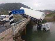
Recent accidents occurring on bridges and viaducts around Istanbul showed that the current safety barriers specified by IMM lack the desired properties. Figure 2 shows devastating result of an truck accident on a bridge deck [ Atahan, 2016 Atahan, A.O. (2016). Heavy Containment Bridge Rails in Turkey. Transportation Research Board, AFB20(2) International Activities Subcomittee, Informal presentation, Washington D.C. ]. Recently, IMM decided to replace existing bridge barriers in the city limits with crash tested and adequate heavy containment level (HCL) barriers. The objective of this study is therefore to design, analyze and test a HCL bridge rail to be used on bridges and viaducts on increased risk locations, within the city limits of Istanbul. An initial bridge rail design was chosen based on engineering judgement and past experiences. A versatile three-dimensional finite element program LS-DYNA was used to perform the initial dynamic evaluations of the initial bridge rail to verify its adequacy and fine tune design flaws [ LSTC, 2016 LSTC (2016). LS-DYNA Keyword User’s Manual. Livermore Software Technology Corporation, Livermore, California, 2016. ]. The final design was successfully crash tested to verify finite element analysis findings. This study is of importance since the HCL bridge barrier, called YIM04, is the first barrier fully developed by Turkish researchers and is currently in use on several bridge decks in Istanbul to improve transportation safety.

Bridge rail failure due to a heavy vehicle impact in Istanbul [ Atahan, 2016 Atahan, A.O. (2016). Heavy Containment Bridge Rails in Turkey. Transportation Research Board, AFB20(2) International Activities Subcomittee, Informal presentation, Washington D.C. ]
2. European Crash Test Standard EN1317 on HCL Bridge Rails
European crash testing guidelines for vehicle restraint system, EN1317, is first established in 1998 for the purpose of providing crashworthy road restraint systems for the European roads [ CEN, 2014 CEN (2014). European Committee for Standardization. European Standard EN1317, Testing and Evaluation of Road Restraint Systems, Brussels. ]. Similar to the U.S. practice, all new safety hardware, such as safety barriers, crash cushions, end terminals and transitions should meet the requirements of EN1317 before put in use on European highway system. Table 1 lists the most recent parts of EN1317 European Standard. In EN1317 part 1, terminology and general criteria for test methods are presented. After this introductory section, the next section, EN1317 part 2 describes the testing and acceptance criteria of safety barriers through full-scale crash tests. In order to satisfy crash test requirements, the bridge rail and test vehicle must fulfill requirements regarding general behavior, vehicle occupant impact severity and deformations. These requirements can be summarized under five items, i.e., safety barrier behavior, test vehicle behavior, impact severity, vehicle deformation and deformation of safety barrier. The working width class is determined from the measured lateral deformation of the safety barrier during crash test. These classes range from W1 to W8 for lateral deformations from less that 0.6 m to more than 3.5 m, respectively. EN1317 parts 3, 4, 5 and 6 deal with crash cushions, transitions, product certification and pedestrian paraphets, repectively [ CEN, 2014 CEN (2014). European Committee for Standardization. European Standard EN1317, Testing and Evaluation of Road Restraint Systems, Brussels. ].
Parts of EN1317 European Standard [ CEN, 2014 CEN (2014). European Committee for Standardization. European Standard EN1317, Testing and Evaluation of Road Restraint Systems, Brussels. ]
The impact resistence of HCL bridge rails are evaluated using full-scale crash tests. As shown in Tables 2 and 3 , high containment performance level (H4b) requires two crash tests, namely TB11 and TB81 [ CEN, 2014 CEN (2014). European Committee for Standardization. European Standard EN1317, Testing and Evaluation of Road Restraint Systems, Brussels. ]. Bridge rail has to satisfy test requirements, such as minimal occupant injury risks in small car impact (TB11), adequate strength to withstand dynamic loads in truck impact (TB81) and vehicle stability criteria during both crash tests. Designing such a barrier is a complicated and difficult task.
Barrier impact test descriptions in EN1317 [ CEN, 2014 CEN (2014). European Committee for Standardization. European Standard EN1317, Testing and Evaluation of Road Restraint Systems, Brussels. ]
Containment levels in EN 1317 [ CEN, 2014 CEN (2014). European Committee for Standardization. European Standard EN1317, Testing and Evaluation of Road Restraint Systems, Brussels. ]
3. European vs. U.S. Crash Testing Details of HCL Bridge Railings
Heavy contaiment bridge rails are designed to safely contain and redirect heavy goods vehicle when they run of the road and impact the bridge rail. They should be strong enough to withstand enourmous impact loads while flexible enough to minimize occupant injury risks.
There are different heavy containment level bridge rail designs in the world that are crash tested either according to EN 1317 or American Standards MASH09 or NCHRP Report 350. These barriers are generally made out of concrete or steel. An online guide to bridge railings approved by the U.S. Federal Highway Administration, FHWA, can be found at FHWA web site [ FHWA, 2017 FHWA (2017). Online Guide to Bridge Railings. TF 13, Federal Highway Administration, https://safety.fhwa.dot.gov/roadway_dept/policy_guide/road_hardware/barriers/bridgerailings/, Washington, D.C.
https://safety.fhwa.dot.gov/roadway_dep...
]. For these designs the most essential parameter is the strength, load transfer mechanism and geometry of the barrier, such as top height and material thickness. According to MASH09 or NCHRP Report 350 HCL bridge railings are tested with a 36,000 kg tractor-tank trailer traveling at 80 kph and impacting the barrier at 15 degrees [ AASHTO, 2009 AASHTO (2009). Manual for Assessing Safety Hardware, MASH09. American Association of State Highways and Transportation Officials, Washington D.C. ;Ross et al., 1993 Ross, Jr., H.E., Sicking, D.L., Zimmer, R.A. and Michie, J.D. (1993). Recommended Procedures for the Safety Performance Evaluation of Highway Features. NCHRP Report 350, Washington, D.C. ]. On the other hand, in Europe similar test is performed with a 38,000 kg tractor trailer traveling at 65 kph with impact angle of 20 degrees [ CEN, 2014 CEN (2014). European Committee for Standardization. European Standard EN1317, Testing and Evaluation of Road Restraint Systems, Brussels. ]. It is important to note that during these tests the impact energies exerted on HCL barriers according to MASH09, Report 350 and EN1317 are 595 kJ, 595 kJ and 725 kJ, respectively. This suggests that HCL bridge railings successfully passed the EN1317 testing criteria is likely to satisfy MASH09 requirements.
4. YIM04 Bridge Rail
Recently, Yimtas Corporation, a well-known Istanbul based guardrail manufacturing company, was asked by the IMM to replace existing lower standard bridge rails in Istanbul with HCL ones. The design, called YIM04, is intended, similar to other commercially available bridge rails, to provide safe containment and redirection for the impacting vehicles. Development phase for the YIM04 bridge rail was based on engineering judgement and past experience of bridge rail performances.
As shown in Figure 3 , YIM04 design is consisted of 5 mm thick steel C150x90 posts welded to 15 mm thich base plate, 6 mm thick triangular post-to-base plate supports, 3 mm thick top and rear rails, 2.5 mm thich thrie rail and 6 mm thick spacer. Note that the posts were anchored to the concrete deck below using 5 M16x250 mm threaded bolts. Table 4 provides material property details of the YIM04 bridge rail elements. Overall geometry, such as top height, system width of the YIM04 was examined carefully to make sure the design is flexible enough for small car impact and strong enough for tractor trailer impact. The next sub sections describe the development and analysis details of the HCL bridge rail, YIM04.

Details of YIM04 heavy containment level bridge rail (a) solid drawing, (b) front and top view, (c) side view
5. Methodology
Before going into a costly full-scale crash testing, a detailed finite element simulation study was performed on YIM04. A highly non-linear and large deformation finite element code LS-DYNA developed by the Livermore Software Technology Corporation (LSTC) was used to model the barrier and simulate the vehicle-barrier impact event [ LSTC, 2016 LSTC (2016). LS-DYNA Keyword User’s Manual. Livermore Software Technology Corporation, Livermore, California, 2016. ]. Details of the bridge rail and both vehicle models are explained below.
5.1. Finite Element Model of Heavy Containement Level Bridge Rail – YIM04
A picture of the barrier model is shown in Figure 3 . As shown in these figures the model is consisted of C shaped steel post (1), upper box beam (4), thrie rail (2), rear box connectors (5), L-shaped connectors (8), spacer block (3), base plate (6), base plate to post support (7) and concrete deck (9). The YIM04 model consisted of 67,919 nodes, 46,605 shell and 12,501 solid elements. Shell elements represented the steel members of the model while solid elements represented the bridge deck. The shell elements of the thrie rail, box beam and other part that are expected to undergo direct vehicle contact and experience severe deformations are modeled with full integration formulation to accurately represent the complex interactions and behavior. All other elements were modeled with default element formulation for computational efficiency.
In an actual YIM04 installation, connections between the members, such as post to spacer block and thrie beam to spacer block were established using bolts and nuts. To accurately represent the behavior of these connections during full-scale crash testing CONSTRAINED_SPOTWELD option in LS-DYNA was used [ LSTC, 2016 LSTC (2016). LS-DYNA Keyword User’s Manual. Livermore Software Technology Corporation, Livermore, California, 2016. ]. By definition, this option keeps members connected until a certain force criteria is met. Then the connection fails and members allow moving freely. To determine the required force level that fails a bolt, a detailed post-to-rail connection model was constructed using LS-DYNA. The behavior of connection was examined under different loading conditions. A reasonable failure criterion obtained from the component simulation was used in the post-to-rail connection model [ Atahan and Bonin, 2006 Atahan A.O. and Bonin G. (2006). Numerical analysis of an H4a heavy containment level transition. Int. J. Heavy Vehicle Systems, Inderscience Enterprises, 13(4), 351-365. ].
Since steel is expected to sustain 38,000 kg truck impact and experience possible crushing, large plastic deformations are likely to occur in the barrier parts. To account for these, a piecewise linear plastic material definition was used to model the steel elements [ Vesenjak et al., 2005 Vesenjak M., Borovinsek M. and Ren Z. (2005). Computational and experimental crash analysis of the road safety. Engineering Failure Analysis, 12, 963-973. ,Atahan and Bonin, 2006 Atahan A.O. and Bonin G. (2006). Numerical analysis of an H4a heavy containment level transition. Int. J. Heavy Vehicle Systems, Inderscience Enterprises, 13(4), 351-365. ]. Since no failure is expected in concrete a rigid material modeling is used to represent concrete deck.
It is a fact that splice connections generate weaker cross-sections due to the reduced effective rail area at the bolt holes, and these connections are prime locations for stress concentrations. As reported in many full-scale crash tests, failure initiates at a splice connection resulting complete rupture of rail. Special attention was paid to develop an accurate splice model for the YIM04 model. After experimenting several options, including an explicit bolted connection, it was decided that the use of an equivalent bolt opening area at the splices could represent the behavior of bolted connection. Previous simulations show that this model proved to be a fairly accurate and immensely cost-effective in capturing the potential failure behavior at splice connections [ Atahan and Cansiz, 2005 Atahan A.O.and Cansiz O.F. (2005) Impact analysis of a vertical flared back bridge rail-to-guardrail transition structure using simulation, Finite Elements in Analysis and Design, Elsevier Science Ltd., 41, 371–396. ]. The anchoring bolts used to secure the post base plate to concrete deck on the other hand were modeled explicitly with a failure criteria.
5.2 Vehicle Models
After the development of YIM04 model, a small passenger car and a large tractor trailer models were necessary to impact the barrier. A Geo Metro model and a tractor trailer model considered to be good representative of actual size vehicles, were obtained from the National Crash Analysis Center (NCAC) and was used in the study [ FEMA, 2002 FEMA (2002). Finite Element Model Archive, FHWA/NHTSA National Crash Analysis Center, http://www.ncac.gwu.edu/vml/models.html, Virginia.
http://www.ncac.gwu.edu/vml/models.html...
]. Both vehicle models were used in many previous studies with success [ Atahan, 2009 Atahan, A.O. (2009). Vehicle crash test simulation of roadside hardware using LS-DYNA: a literature review. International Journal of Heavy Vehicle Systems 17(1), 52-75. ]. Pictures of both vehicles are shown in Figure 4 .

900 kg car (left) and 38,000 kg tractor trailer (right) models [ FEMA, 2002 FEMA (2002). Finite Element Model Archive, FHWA/NHTSA National Crash Analysis Center, http://www.ncac.gwu.edu/vml/models.html, Virginia.
http://www.ncac.gwu.edu/vml/models.html... ]
5.3 TB11 Simulation
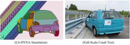
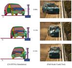
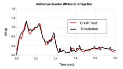
After the final modifications on the vehicle model, the simulation was setup according to TB11 conditions. This test is intended to evaluate the occupant injury criteria based on impact loads on the vehicle. As shown in Figure 5 , vehicle was positioned in front of the barrier at 20 degrees impact angle. The vehicle speed was 100 km/h. In this simulation no dummy is used. Simulation was run about 0.320 sec until the vehicle exited the installation. As shown in Figure 6 , vehicle left the barrier in a stable and upright position. The velocity of vehicle at exit of installation was approximately 82 km/h. This represented approximately 20 percent decrease in vehicle speed compared to initial impact speed. This significant decrease shows the amount of energy absorbed by the barrier. A picture of the deformed shape of the barrier after TB11 simulation is shown in Figure 7 . As shown in this figure, spacer blocks behaved like shock absorbers thus improved the flexibility of the HCL barrier. As a result of this flexibility occupant injury criteria, or Acceleration Severity Index (ASI) calculated based on the measured acceleration values during crash testing, was well within the acceptable limits (see Figure 8 ). Based on the simulation predictions, it was determined that YIM04 bridge rail successfully contained and redirected 900 kg vehicle with minimal injury risk to occupants.

5.4 TB81 Simulation
A second simulation study, as shown in Figure 9 , was also performed to evaluate the structural adequacy of the barrier. As described by test TB81, 38,000 kg tractor trailer was positioned in front of the barrier. The vehicle contacted the barrier at 20 degrees and the velocity of the vehicle was 65 km/h just before the impact. Following the initial contact, as shown in Figure 10 thrie rail and box beam began to deform and absorbed the initial impact by the tractor. When the trailer impacted the barrier at around 0.4 seconds into the simulation the deformation of the barrier reached its maximum level. At 1.050 seconds after the initial impact vehicle became parallel with the barrier and beyond this time vehicle is redirected away from the barrier. At 1.4 seconds after the initial impact vehicle exited the barrier in a stable manner. The exit angle was approximately 5 degrees. The velocity of vehicle at exit of installation was approximately 44 km/h representing approximately 32 percent decrease compared to initial speed. This was due to plastic deformation of barrier parts during impact event. Damage to YIM04 barrier after TB81 test was significant. As shown in Figure 11 , the lateral deformation of the barrier was approximately 1,130 mm.


6. Full-Scale Crash Testing
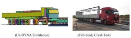
After performing two successful simulation studies for tests TB11 and TB81, a large full-scale crash test program was performed. Crash tests were run at CSI-SPA proving ground facility located in Milano, Italy during summer of 2013. These tests were intended to both verify the simulation findings and get a final approval for use of this HCL bridge rail on European highway bridges.
6.1 Crash Test TB11
As shown in Figures 5 and 6 , a full-scale crash test, designated as 0062/ME/HRB/13, was performed on YIM04 barrier according to EN1317 test TB11 conditions [ CSI, 2013a CSI (2013a). TB11 crash tests on YIM04 bridge rail. Test No. 0062/ME/ HRB/13, CSI-SPA, Crash Test Facility, Bollate, Milano. ]. A 60 m long installation was setup on concrete deck and the impact point, as described in EN1317-2, was at 20 meters from the beginning of the barrier. A 1991 model Fiat Uno was used as the test vehicle. The total mass of the tested vehicle was 900 kg with the addition of dummy and measurement devices. Vehicle positioned in the test track, the vehicle accelerated toward the test article at an angle of 20 degrees using a remote control and GPS system and impacted the barrier at 101.5 km/h. Behavior of the barrier and the vehicle are illustrated in Figure 6 . As expected 900 kg vehicle was not able to deform the barrier significantly. As illustrated in Figure 7 , spacer blocks at the impact region were compressed and absorbed the kinetic energy of the vehicle. Data collected from accelerometer installed at Fiat Uno’s center of gravity was used to calculate the ASI and as shown in Figure 8 , the result was 1.2 which proves the acceptability of the HCL barrier. Results of TB11 crash test showed that the barrier is flexible enough to protect its occupants from potential injuries.
6.2 Crash Test TB81
After repairing damaged thrie rail and few spacer blocks another full-scale crash test, designated as 0063/ME/HRB/13, was performed on YIM04 barrier according to EN1317 test TB81 [ CSI, 2013b CSI (2013b). TB81crash tests on YIM04 bridge rail, Test No. 0063/ME/ HRB/13, CSI-SPA, Crash Test Facility, Bollate, Milano. ]. As shown in Figure 9 , a 37390 kg IVECO model tractor trailer impacted the barrier with a speed of 66 km/h and at an angle of 20 degrees. The impact point was also around 20 m away from the beginning of the barrier. Following the initial contact, as shown in Figure 10 , thrie rail and box beam began to deform and absorbed the initial impact loads. When the trailer impacted the barrier at around 0.42 seconds the deformation of the barrier reached its maximum level. Similar to LS-DYNA simulation, at 1.1 seconds after the initial impact vehicle became parallel with the barrier. At this point deformation in barrier was significant. At 1.45 seconds after the initial impact vehicle exited the barrier in a stable manner. The exit angle was approximately 4 degrees. The velocity of vehicle at exit of installation was approximately 41 km/h representing approximately 37 percent decrease compared to impact speed. This was due to plastic deformation of barrier parts during impact event. As shown in Figure 11 , the lateral deformation of the barrier was approximately 1,100 mm agreeing favorably to that obtained from finite element simulation study. When the crash tests results are evaluated, YIM04 barrier, as predicted by LS-DYNA study, satisfied the HCL baridge rail crash test requirements in EN1317 standard.
7. Results and Conclusions
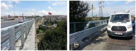
This paper deals with designing, analyzing and testing a high containment level rail to be used on bridges and viaducts on increased risk locations, within the city limits of Istanbul. First of all a structurally adequate design was constructed using steel elements. Then, a versatile three-dimensional finite element program LS-DYNA was used to construct the model and perform the finite element impact analysis on the design. These anaysis are intended to predict the crash test performance of the bridge rail in a cost effective way. A highly sophisticated, versatile finite element program, LS-DYNA was used for the anaysis. After successfully completing the crash test simulations, design was subjected to full-scale crash testing before its final approval. 900 kg car and 38000 kg tractor trailer crash tests performed at Milano crash testing facility proved the adequacy of the bridge rail for use on bridges and viaducts. This study is of importance since this barrier is the first barrier fully developed by Turkish researchers. As shown in Figure 12 , currently YIM04 barrier is in use on bridges and viaducts around Istanbul to provide adequate safety and security for hıghway users and improve traffic safety in Istanbul.
References
- AASHTO (2009). Manual for Assessing Safety Hardware, MASH09. American Association of State Highways and Transportation Officials, Washington D.C.
- AASHTO (2011). Roadside Design Guide, 4th Edition. American Association of State Highways and Transportation Officials, Washington D.C.
- Atahan, A.O. (2016). Heavy Containment Bridge Rails in Turkey. Transportation Research Board, AFB20(2) International Activities Subcomittee, Informal presentation, Washington D.C.
- Atahan, A.O. (2009). Vehicle crash test simulation of roadside hardware using LS-DYNA: a literature review. International Journal of Heavy Vehicle Systems 17(1), 52-75.
- Atahan A.O. and Bonin G. (2006). Numerical analysis of an H4a heavy containment level transition. Int. J. Heavy Vehicle Systems, Inderscience Enterprises, 13(4), 351-365.
- Atahan A.O.and Cansiz O.F. (2005) Impact analysis of a vertical flared back bridge rail-to-guardrail transition structure using simulation, Finite Elements in Analysis and Design, Elsevier Science Ltd., 41, 371–396.
- CEN (2014). European Committee for Standardization. European Standard EN1317, Testing and Evaluation of Road Restraint Systems, Brussels.
- CSI (2013a). TB11 crash tests on YIM04 bridge rail. Test No. 0062/ME/ HRB/13, CSI-SPA, Crash Test Facility, Bollate, Milano.
- CSI (2013b). TB81crash tests on YIM04 bridge rail, Test No. 0063/ME/ HRB/13, CSI-SPA, Crash Test Facility, Bollate, Milano.
- FHWA (2017). Online Guide to Bridge Railings. TF 13, Federal Highway Administration, https://safety.fhwa.dot.gov/roadway_dept/policy_guide/road_hardware/barriers/bridgerailings/, Washington, D.C.
» https://safety.fhwa.dot.gov/roadway_dept/policy_guide/road_hardware/barriers/bridgerailings/ - FEMA (2002). Finite Element Model Archive, FHWA/NHTSA National Crash Analysis Center, http://www.ncac.gwu.edu/vml/models.html, Virginia.
» http://www.ncac.gwu.edu/vml/models.html - IMM (2016). Istanbul Traffic Safety Strategic Plan, Technical Report IBB-3-TS04, Istanbul Metropolitan Municipality.
- Kubler J. (2008). Improvement of safety barriers on German bridges - Results of impact test with heavy lorries, Federal Highway Research Institute (BASt), Germany.
- LSTC (2016). LS-DYNA Keyword User’s Manual. Livermore Software Technology Corporation, Livermore, California, 2016.
- Ross, Jr., H.E., Sicking, D.L., Zimmer, R.A. and Michie, J.D. (1993). Recommended Procedures for the Safety Performance Evaluation of Highway Features. NCHRP Report 350, Washington, D.C.
- TRA (2015). Traffic Safety Handbook. Turkish Road Association, Department of Transportation, Ankara.
- TUİK (2016). Vehicle data on Turkish Highways. Turkish Statistics Organization, Ankara.
- Vesenjak M., Borovinsek M. and Ren Z. (2005). Computational and experimental crash analysis of the road safety. Engineering Failure Analysis, 12, 963-973.
Publication Dates
-
Publication in this collection
02 July 2018 -
Date of issue
2018
History
-
Received
19 Nov 2017 -
Reviewed
02 Dec 2017 -
Accepted
31 Mar 2018


