
Abstract
This research presents a study of the behavior of built-up compressed steel members composed of concentric hot rolled circular hollow sections. The use of these members is an innovative solution of practical interest for situations in which a single member does not reach the required compressive strength. Some technically and economically viable design and fabrication solutions to built-up members composed of concentric hot rolled circular hollow sections are presented. For the validation of numerical results, models of singular hollow sections are made and compared to the EN 1993-1-1, and the results obtained with numerical models were satisfactory. The compression resistance of these numerical models differs less than 9% from the EN 1993-1-1 values. Once the numerical modeling was validated, the study of built-up members was made, considering the tubes always united at the extremities by end plates, and along the length by fixed interconnections or sliding interconnections or, furthermore, without interconnections. For these three different conditions, several numerical models using FEM via Abaqus software were simulated to obtain and compare the compression resistance. The results show that these built-up sections with fixed and sliding interconnections have very similar behavior to the results obtained with European Standard procedure, when considering equivalent areas and inertias for the built-up section. Also, it shows that this observation does not apply to the sections without interconnections. Comparative graphs of compression resistance curves were generated, as also some graphs that show the distribution of the compressive force between each member of the built-up section. Finally, a formulation for the design of built-up sections without interconnections along the tubes was proposed to avoid robust computational methods.
Keywords
Steel Structures; Built-up Concentric Tubular Sections; Axial Compression; Structural Stability
1 INTRODUCTION
Circular hollow steel sections (CHS) have homogeneous mass distribution around the centroid, which gives them equal geometric properties taking as reference any axis passing through its center. For this reason, the moment of inertia of these sections is about 1.8 times higher and the radius of gyration about 1.4 times higher than H sections of the same mass and equivalent external dimensions. Consequently, from the material consumption perspective, members with circular cross sections are especially advantageous when subjected to axial compression. Additionally, these members are very efficient when used in structures under dynamic forces. They present also a higher corrosion resistance due the absence of corners in transversal section ( RONDAL et al., 2008 Rondal, J.; Würker, K. G., (2008). Dutta, D. Design guide for circular hollow section (CHS) joints under predominantly static loading. 2nd Ed. CIDECT. ).
In some situations, the compression resistance (in this work, compression resistance indicates the axial force equal to the characteristic buckling resistance of the member) of the members can be lower than the required one. The usual ways to solve this problem using hot rolled hollow sections (these sections are limited in size because of the manufacturing process) are the direct welded connection of tubular profiles or the assembly based on lattice bars or connection plates, as shown in figures 1 1b.
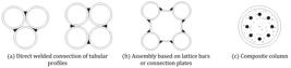
These solutions can cause severe impact on the architectural project, and bring complicating factors in manufacturing, erection and structural design. The welding regions in parallel built-up members are complicate to perform and the connections between beams and columns may be penalized by large eccentricities. An option, which practically does not cause impact in the architecture, is the use of composite columns, filling the tubular steel profile with concrete (reinforced or not) – see Figure 1 c. However, this option can strongly affect the operational viability of the construction, since it is necessary to cast concrete at the construction site and it increases the final weight of the structure.
In this work, the use of built-up compressed steel members composed of concentric hot rolled circular hollow sections ( Figure 2 ) is proposed, limited to the case where only two tubes are used. This is an innovative solution that makes possible to increase the compression resistance without changing the architecture and without using other materials, such as concrete.

A numerical study of the structural behavior of the built-up members composed of concentric hot rolled circular hollow sections, henceforth called CHRCHS, is presented to determine the compression resistance of these members, using the finite element analysis software ABAQUS ( Simulia, 2013 Simulia, D. S., (2013). ABAQUS 6.13 User’s manual. Dassault Systems, Providence, RI. ). The inner and the outer tubes of CHRCHSs are always united at the extremities by end plates, and along the length these two tubes can be united by fixed interconnections or sliding interconnections or, furthermore, have no interconnection. Calculation procedures for CHRCHS resistance of each type of solution are proposed based on the results analysis, that applies to sections that are not subjected to local buckling.
2 CIRCULAR HOLLOW SECTIONS MEMBERS BEHAVIOR UNDER AXIAL COMPRESSION
2.1 Residual Stresses and Geometric Imperfections
Steel tends to have a perfectly plastic behavior when the internal stresses reach the yield stress. In case of compressed members with initial crookedness, the yielding of the midspan section begins in the concave face in the most external fiber of the section (where the stresses are higher). As the force and the displacements increase, the internal bending moment raises and the yielding spread to the interior of the section, forming the plastic hinge. At this point, the member becomes a plastic mechanism and collapses, thus determining the compression resistance of the member ( Chen and Han, 2007 Chen, W. F.; Han, D. J., (2007). Plasticity for structures engineers, Springer-Verlag, New York, USA. ).
In hot rolled sections, the residual stresses are the result of the non-uniform cooling of the steel cross section, from lamination to ambient temperature, resulting in a self-equilibrated stresses distribution in the cross section that varies from compression to tension. For circular hollow sections (CHS) the residual stresses are linearly distributed along the thickness and there is no temperature variation along the circumference of the cross section, with inferior values than the values of residual stresses found in open cross sections, such as I, U and L profiles. According to European Convention for Constructional Steelwork ( ECCS, 1976 ECCS – European Convention for Constructional Steelwork – Committee 8, (1976). Manual on stability of steel structures, 2nd Ed. ), members with hot rolled circular hollow sections are not significantly affected by residual stresses. In these sections, there is a maximum linear variation of -15% to +15% of the steel yielding resistance, as shown in Figure 3 . Nowadays these values are still considered acceptable ( Grilo, 2015 Grilo, L.F., (2015). Study of the behavior of built-up compression steel members composed of concentric hot rolled circular hollow sections. MSc. Dissertation (in Portuguese), Federal University of Minas Gerais, Brazil. ). Recently, Law and Gardner (2012) Law, H. K., Gardner, L., (2012). Lateral instability of elliptical hollow section beams. Engineering Structures, v. 37. obtained the residual stresses in a similar profile, with elliptical cross section, and concluded that these stresses correspond to 10 to 15% of the steel yielding resistance, confirming the previous conclusions about the circular hollow sections.

The initial geometric imperfection, or initial crookedness, of steel members is inherent to the fabrication process and can be amplified during transportation and assembly of the structure. The value of this imperfection used in the generation of the axial compressive strength curves by European design specification – EN 1993-1-1 ( Eurocode, 2005 Eurocode (2005). EN 1993-1-1: Design of steel structures - Part 1-1: General rules and rules for buildings – Eurocode 3. ) – is bellow to the tolerance values prescribed by the manufacturing specifications ( Beedle, 1991 Beedle, L.S., (1991). Stability of metal structures: A world view, 2nd Ed., Structural Stability Research Council, Lehigh University, Bethlehem. ; Galambos, 1998 Galambos, T. V., (1998). Guide to stability design criteria for metal structures, 5th Ed. Wiley, New York. ). This difference awakes a concern about the actual value of the member’s strength when compared to that evaluated according the design specification ( Bild and Trahair 1989 Bild S., Trahair N. S., (1989) In-plane strengths of steel columns and beam-columns. Journal of Constructional Steel Research, 13(1), 1–22. ).
The limit for the initial crookedness in the manufacturing specifications for hot rolled circular hollow sections (CHS) is , were is the length of the member ( Eurocode, 2006 Eurocode (2006). EN 10210-2: Hot finished structural hollow sections of non-alloy and fine grain steels—Part 2: Tolerances, dimensions and sectional properties, Eurocode. ; ASTM, 2005 ASTM (2005). Standard specification for hot-formed welded and seamless carbon steel structural tubing, ASTM A501, West Conshohocken. ), while the initial crookedness adopted by EN 1993-1-1 is ( Eurocode, 2005 Eurocode (2005). EN 1993-1-1: Design of steel structures - Part 1-1: General rules and rules for buildings – Eurocode 3. ; Beer and Schulz, 1970 Beer H., Schulz G., (1970) “Bases théoriques des courbes européennes de flambement” Construction Métallique, 3, 37–57. ).
2.2 Compression Resistance Force According to EN 1993-1-1
For the determination of the compression resistance of cross-sections, not subjected to local buckling, EN 1993-1-1 ( Eurocode, 2005 Eurocode (2005). EN 1993-1-1: Design of steel structures - Part 1-1: General rules and rules for buildings – Eurocode 3. ) provides the following expression:
where is a reduction factor related to the compressive strength, is the gross cross-section and is the yielding resistance of the steel. The effects of the initial crookedness are taken in account by the factor , given by:
In this expression, is the non-dimensional slenderness, defined as:
where is the elastic critical force, and, for the strength curve “a”, from EN 1993-1-1 ( Eurocode, 2005 Eurocode (2005). EN 1993-1-1: Design of steel structures - Part 1-1: General rules and rules for buildings – Eurocode 3. ), that includes tubular circular profiles, is equal to:
3 SOLUTION DESIGN PROPOSAL
3.1 End Plate Joints
In order to comprehend the behavior of built-up sections formed by concentric tubular sections, the possible ways of assembling this type of composition should be studied. In this context, it is necessary to solve mainly two problems: the interconnections along the tubular sections and the connections of the tubes with the end plates (flanges).
To connect the two tubular sections at the ends, an end plate with central opening was chosen. The outer tube was joined to the end plate with fillet welding, and the inner tube was joined to the end plate with a single bevel butt-welding, with the chamfer made in the end plate opening, as shown in Figure 4 .

3.2 Tubes Interconnections
The end plate does the compatibility of the displacements at the extremities of the tubes, but it may be necessary to match the transverse displacement of the inner and outer tubes, in some points, along the members. From the viewpoint of designing and manufacturing, the design of these interconnections between the tubes should be solved. To ensure that each member of a double symmetric built-up section works structurally together with the other member of the assembly, the standard EN 1993-1-1 ( Eurocode, 2005 Eurocode (2005). EN 1993-1-1: Design of steel structures - Part 1-1: General rules and rules for buildings – Eurocode 3. ) recommends that the connecting elements along the members respect the equation:
where is the minimum radius of gyration of individual component and is the maximum distance between the interconnections.
In this paper, the simulations were performed considering three types of assemblies: without interconnections, with fixed interconnections and with sliding interconnections. The last two assemblies types can be manufactured as described in the following subitems, always respecting the maximum distance from Equation (5).
3.2.1 Fixed Interconnections
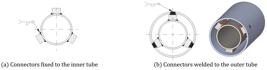
One of the proposed options for engaging the tubes together is the use of connectors welded on the tubes. In the production of CHRCHSs, the steps for placing these interconnections can be divided into three. In the first step, the connectors must be fixed with a fillet weld on the outer face of the inner tube, as shown in Figure 5 a. In the second step, the outer tube must be drilled at the points above the places where the connectors will be. In the third step, a butt weld should be performed, welding the connectors to the outer tube, as shown in Figure 5 b.
3.2.2 Sliding Interconnections
The second option for engaging the tubes together is the use of sliding interconnections. To assemble, initially the outer tube should be drilled in the positions of the interconnections. Thereafter, the tubes should be concentrically positioned and the pins should be placed in the holes, touching the inner tube. Finally, a fillet weld should be performed, welding the pins and the outer tube. The assembly is shown in Figure 6 .

4 DEVELOPMENT AND VALIDATION OF THE NUMERICAL MODELS
Initially, the numerical models of isolated tubes with initial crookedness subject to axial compression, considering several element and procedure types were developed on ABAQUS 6.13 ( Simulia, 2013 Simulia, D. S., (2013). ABAQUS 6.13 User’s manual. Dassault Systems, Providence, RI. ). By the comparison of the values obtained and the EN 1993-1-1 ( Eurocode, 2005 Eurocode (2005). EN 1993-1-1: Design of steel structures - Part 1-1: General rules and rules for buildings – Eurocode 3. ), the S8R element, that adapts perfectly to the geometry of the problem, and the modified Riks method (arc length method) were chosen to determinate the compression resistance ( Castro e Silva, 2006 Castro e Silva, A. L. R., (2006). Non-linear numerical analysis of local buckling of structural steel profiles under single axis compression. PhD Thesis (in Portuguese), Federal University of Minas Gerais, Brazil. ).
The isolated tubes models were generated with initial crookedness taken as , the same value adopted on the procedure of EN 1993-1-1 ( Eurocode, 2005 Eurocode (2005). EN 1993-1-1: Design of steel structures - Part 1-1: General rules and rules for buildings – Eurocode 3. ), with elastic-plastic bilinear stress-strain diagram for steel. The residual stresses were neglected in the numerical models since their variations occur only along the thickness and have an insignificant effect on the global behavior of the structure. One quarter of the tube was modeled, taking advantage of the longitudinal and the transversal symmetry planes.
To find the best discretization of the models, a sensibility test of the mesh was made with the circular hollow sections CHS 73 x 3.6 (diameter/thickness ratio, , equal to 20) and CHS 323.8 x 6.4 ( equal to 50), with slenderness parameters approximately 0.80 and 1.60, respectively. The results showed that, for a number of elements in the cross section higher than 10, the difference between the results is negligible for all models tested. Therefore, aiming to reduce the error in the modeling to a minimum and optimizing the processing time, it was adopted 15 elements in the cross section in this work.
Sixty numerical models were analyzed with three different cross sections. It was considered the circular hollow sections: CHS 73.0 x 7.1, CHS 73.0 x 3.6 and CHS 323.8 x 6.4, with equal to 10.3, 20.3 and 50.6, respectively. The curves of versus were obtained generating the plots of the differences between these curves and the curves obtained with the EN 1993-1-1 ( Eurocode, 2005 Eurocode (2005). EN 1993-1-1: Design of steel structures - Part 1-1: General rules and rules for buildings – Eurocode 3. ) procedure, as can be seen in Figure 7 .

The maximum difference observed between the numerical results and the results evaluated in accordance with EN 1993-1-1 ( Eurocode, 2005 Eurocode (2005). EN 1993-1-1: Design of steel structures - Part 1-1: General rules and rules for buildings – Eurocode 3. ) was under 9.3%. Therefore, the numerical modeling parameters were considered satisfactory for this study, and were applied for the built-up models.
5 NUMERICAL ANALYSIS OF CHRCHS
5.1 Numerical Models
Once the numerical simulation process was validated by the single tubes model, simulations were performed with the CHRCHSs numerical models. Seventeen different combinations of cross sections were considered, each one with the three different types of interconnections (fixed, sliding and free) along the tubes. In all models, the ends of the tubes were considered rigidly coupled between themselves. This consideration assumes that the end plate made a perfect transference of the load to the inner and outer tubes. All the models were made with an initial crookedness equal to , and each cross section of CHRCHS was simulated with a different , by varying the length of the members. The cross sections of the simulated models are presented in Table 1 .
All the models were generated considering the yield strength equal to 350 MPa, and bilinear stress-strength diagram of steel, with inclination of 1/10,000 in the plastic part. Models with ranging from 0.07 to 2.66 were analyzed, with young modulus equal to 200 GPa, and the results are shown in the following subitems. In addition to the compression resistance curve comparisons, there were obtained some curves of compression force distribution between the tubes of CHRCHS, along the loading steps.
5.2 Fixed Interconnections versus EN 1993-1-1
Assuming that it is possible to ensure that both tubes of CHRCHSs work perfectly coupled, the compression resistance of the built-up section could be calculated using the EN 1993-1-1 ( Eurocode, 2005 Eurocode (2005). EN 1993-1-1: Design of steel structures - Part 1-1: General rules and rules for buildings – Eurocode 3. ) formulation for a circular hollow section single member, considering the equivalent areas and inertias of the cross section, which are calculated by the sum of both single sections properties. The comparison of the values of χ obtained according to the EN 1993-1-1 ( ) in relation to those obtained by numerical models with fixed interconnections ( ) are shown in Figure 8 .

As can be seen, there is a fairly uniform qualitative behavior in all models, noticing a pattern in the variation of the difference between and , obtained by varying the non dimensional slenderness of the members. This pattern of variation possibly occurs due to adjustments in the compression resistance curve equation presented in the EN 1993-1-1 ( Eurocode, 2005 Eurocode (2005). EN 1993-1-1: Design of steel structures - Part 1-1: General rules and rules for buildings – Eurocode 3. ). In all tested models, the differences between numerical and analytical results did not reach 9%, which can be considered small, and can be explained by inaccuracies of both, the numerical model and the compression resistance curve equation of the European Standard.
It is also important to observe that the behavior of the obtained curves is similar to those obtained in the calibration model, made for single tubes. This observation allows concluding that the structural behavior obtained with the fixed interconnection CHRCHSs is similar to that of single member with equivalent cross section properties. Therefore, it can be concluded that the fixed interconnection in the numerical models are ensuring that the two tubes of the CHRCHSs work in perfect coupling.
5.3 Fixed Interconnections versus Sliding Interconnections Models
Figure 9 shows the differences between the numerical values of obtained with the sliding interconnection models ( ) in relation to those obtained with the fixed interconnection models ( ).
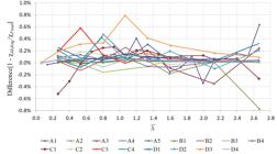
As shown, the difference between and are less than 0.8%, showing that the structural behavior of the CHRCHSs models with both fixed and sliding interconnections are practically the same. The difference presented can be attributed to variations in the numerical models, such as the use of contact in the model when sliding interconnection is simulated, which have a greater complexity of numerical convergence. From the point of view of the compression resistance, this study shows that there is no significant difference between CHRCHSs with sliding and fixed interconnections.
5.4 CHRCHSs without Interconnections versus Fixed Interconnections
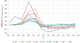
The setting of the interconnections in CHRCHSs significantly complicates their manufacturing, comparing to CHRCHSs without interconnections, which justifies analyzing also the behavior of this type of built-up profile. In the absence of interconnections, the tubes no longer behave in perfect coupling, what makes the compression resistance tending to reduce. Figures 10 and 11 show the relation between the values of obtained with models without interconnections ( ) and those obtained with fixed interconnections models ( ).
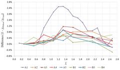

As can be seen, in all models of groups A and B, the differences found between and were less than 3%, which can be considered small. For groups C and D, these differences reach 21%, which is a considerable value. This accentuated difference will be better discussed on Subitem 5.6, in which the distribution of the axial compression force between the tubes along the loading steps will be analyzed.
5.5 Sum of Single Bars Resistance versus CHRCHSs without Interconnections
A first simplified approximation to determine the compression resistance force on CHRCHSs without interconnections is the sum of the resistance of each single tube. The differences between the equivalent value of obtained by the sum of the compression resistance of single tubes ( ), and the value obtained by analyzing the CHRCHSs without interconnections ( ) are shown in figures 12 and 13 . Both and are obtained by the numerical analysis.

As presented in Figure 12 , the maximum difference between and of the CHRCHSs of A and B groups is less than 6%, which can be considered negligible. Although, it can be observed that, up to a value of , the differences show positive values, therefore, the sum of the compression resistance of the single tubes is lower than the resistance calculated by the CHRCHS model without interconnections. Up to this limit, for the analyzed models, the value of the compression resistance force could be calculated, in a simplified way, as the sum of the resistant forces of the single profiles, thus remaining conservative.
From that value on, which varies in each CHRCHS, the results are reversed, and the value of the sum of the compression resistance of the single tubes becomes higher than the resistance calculated by the CHRCHS model without interconnections, reaching the maximum value between 1.2 and 1.6 of . Therefore, between this values of , the determination of the compression resistance force by the sum of the single members resistance can be non-conservative, and its use is not reasonable. This can be explained by the fact that the inner tube becomes unstable before the outer tube.
The same qualitative behavior from the models of groups A and B can be observed in the results of models of groups C and D. However, these latest models present the values of the differences significantly higher when compared to groups A and B, as shown in Figure 13 , between -9% and 19%. From this figure, it can be concluded that, for groups C and D, the calculation of the axial compression resistance by the sum of the compression resistance of single tubes can lead to very conservative values (reaching 19%), but also can lead to dangerous values, with more than 8% of non conservative error.
5.6 Axial Compression Force Distribution
To study the axial compression force distribution through the CHRCHS tubes as the load is applied, some selected models of this paper were evaluated in more detail. On these models, it was determined the axial compression force acting in each tube of the CHRCHS, varying along the load steps.
To determine the force acting on each tube, an approximation based on the average normal stress of the model elements was made. The obtained average stress of each tube was multiplied by the transversal area, and the axial force acting in each tube was estimated. This method to estimate de axial compression force in each tube of CHRCHS contains some inaccuracies. Firstly, the elements may have a small difference in size, because of the FEM mesh adaptations. Another source of inaccuracies is the fact that the tubes are not exactly aligned with the axis of the stress, due to the crookedness of adopted. However, as can be observed in the follow items, the results obtained were acceptable, properly representing the member’s behavior.
In order to explain the obtained results, the versus curves of the C4 models are shown in Figure 14 a, and the differences of versus , for the different interconnections types are shown in Figure 14 b. The axial force distribution versus the load step curves of the model C4, with =1.07, are shown in Figure 15 , also for the different types of interconnections. For comparison purposes, the horizontal dashed lines are indicating the compression resistant force of the single tubes, as well as the sum of the resistance of these members. All the results shown in figures 14 and 15 were numerically generated.
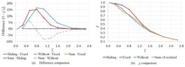
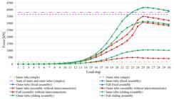
It can be seen in figures 14 and 15:
-
i
Inner tube behavior
The inner tube, with any form of interconnections, supports more axial force than itself when calculated as a single member. It can also be observed that the behavior is similar when using sliding or fixed interconnections, and the curves on the graphic are almost overlapping. However, when the interconnections are not used, the maximum force on the inner tube reduces, but remains higher than the calculated single tube force. This behavior can be explained by the fact that the outer tube stabilizes the inner tube, increasing the maximum force that the inner tube can support. When there are fixed or sliding interconnections, the system works by matching the displacements along the profiles. When there are no interconnections, the compatibility of the displacements is made only by the end plates, resulting in transversal displacements that are not perfectly compatibilized along the tubes.
-
ii
Outer tube behavior
The outer tube, with any forms of interconnection, supports less axial force than itself, when calculated as a single member. This behavior occurs since the outer tube is being used to stabilize the inner tube, which is less fixed. The behavior of the outer tube in models with fixed or sliding interconnections is very similar, as observed for the inner tube.
-
iii
Assembly behavior
When analyzing the whole assembly behavior, it can be seen that with no interconnections, the inner tube reaches the maximum force in load step 24, and the outer tube reaches the maximum force in load step 25 ( Figure 15 ), confirming the fact that the inner tube loses its stability before the outer tube does. For some values of , this behavior causes the maximum axial force of the assembly without interconnections to be lower than the sum of the compression resistance of the single members. This can be observed in the dashed line in Figure 14 a, which reaches its minimum at . In the assemblies in which full compatibility of displacements were obtained (fixed and sliding interconnections), the maximum compression force is always higher than the sum of the single bars compression resistances. As shown in Figure 15 , when the interconnections are used, the maximum forces in the inner and outer tubes occur simultaneously, in load step 25.
The von Mises stresses, in load step 25, are shown in figures 16 and 17 , for the CHRCHS without interconnections and with fixed interconnections, respectively, in MPa.


As shown in Figure 16 , the transversal displacement of the inner tube is larger than that on the outer tube, leading it to become unstable before the outer tube. At the load step 24, the inner tube loses the capacity to support additional compression forces, with almost full cross section yielded. In load step 25, the same behavior is observed in outer tube.
As shown in Figure 17 , when fixed interconnections are used, the maximum axial force assembly is achieved without the inner tube being yielded. This behavior is also the same in the model with sliding interconnections.
By increasing the non dimensional slenderness of the CHRCHS, the stiffness of the inner tube becomes smaller than the one of the outer tube. In this situation, the maximum axial force of the inner tube is smaller than the one of the outer tube, and the outer tube governs the behavior of the CHRCHS without interconnections.
6 PROPOSED DESIGN PROCEDURE
6.1 CHRCHSs with Interconnections
To design a CHRCHS, the present study shows that it is feasible to use FEM models, as described throughout this work. However, although leading to good accuracy results, the use of these models has a high computational processing cost, that makes it extremely difficult to use in practical engineering projects. In attempt to simplify the design, a formulation is proposed in this item, based on the EN 1993-1-1 ( Eurocode, 2005 Eurocode (2005). EN 1993-1-1: Design of steel structures - Part 1-1: General rules and rules for buildings – Eurocode 3. ).
As shown in this work, the behavior of CHRCHSs with fixed or sliding interconnections is similar to a single member behavior when calculated using equivalent cross section properties. Therefore, the compression resistance ( ) of CHRCHS can be calculated by considering equivalents gross area ( ) and moment of inertia ( ), according to the follow equations:
where and and and are the moments of inertia and the gross areas of each single cross section, respectively. Once these properties of the equivalent CHRCHS cross section are determined, the EN 1993-1-1 ( Eurocode, 2005 Eurocode (2005). EN 1993-1-1: Design of steel structures - Part 1-1: General rules and rules for buildings – Eurocode 3. ) design specification can be used to determine the compression resistance of circular hollow sections. As already shown in this work, by using sliding or fixed interconnections, the differences between this procedure and the FEM results are less than 9% for all the studied models.
6.2 CHRCHSs without Interconnections
As shown in this work, if the same procedure proposed to determine the compression resistance of CHRCHSs with interconnections is employed to CHRCHSs without interconnections, it could lead to dangerous results, since the calculated resistance could be higher than the actual resistance.
To propose a conservative procedure to determine the axial compression resistance of CHRCHSs without interconnections, avoiding the use of robust computational methods, the relation between the compression resistance of the single members and of the CHRCHS without interconnections were studied. This approach leads to a conservative procedure since, in some situations, it neglects part of the resistance of the assembly.
As previously shown in this work, the value of may be smaller or greater than the value of , and varies with the non dimensional slenderness of the assembly. The proposed formulation is based on determining the lower envelopment curve of the difference between these values, and using that curve to reduce the calculated. Therefore, this reduced value of can be used to calculate the compression resistance of the built-up section. To perform this analysis, it was initially defined the coefficient :
where and are, respectively, the largest and the smallest values of for the single tubes that composes the CHRCHS, calculated according to EN 1993-1-1 ( Eurocode, 2005 Eurocode (2005). EN 1993-1-1: Design of steel structures - Part 1-1: General rules and rules for buildings – Eurocode 3. ), with the same length of the assembly. Using the calculated values of for all numerical models tested, the curves of versus Difference are shown in Figure 18 , being the value of Difference calculated as:

As shown, the difference can be positive or negative along the curves. When this difference is negative, it means that is higher than , meaning that it is necessary to reduce the value of to be able to safely use it in the CHRCHS compression resistance determination. When this difference is positive, it means that by using in resistance calculation, part of the axial resistance will not be considered.
To determine an equation to predict a factor to reduce the value of , the fitted curve equation was calculated for the lower envelopment of the CHRCHS curves, shown in dashed line in Figure 18 . By using this function, the maximum reduction factor of each value of will be applied, leading to a conservative estimation of the compression resistance. The equation of the dashed curve shown in the graph is:
with a coefficient of determination ( ) equal to 0,97.
The following expression was proposed to calculate the compression resistant force of CHRCHS without interconnections:
with
where e are the compression resistant forces of the inner and outer tubes, respectively, calculated as a single member, according to EN 1993-1-1 ( Eurocode, 2005 Eurocode (2005). EN 1993-1-1: Design of steel structures - Part 1-1: General rules and rules for buildings – Eurocode 3. ), with the same length of the CHRCHS. Due to the exponential form of the function, the use of this formulation for values of higher than 0,88 is not recommended, which is not a major limitation, once CHRCHSs with higher than this value will be geometrically out of proportion.
It is important to notice that, in some cases, the presented formulation neglects a resistance gain that reached 19%. However, the design time reduction could be substantial, and the manufacturing of CHRCHS without interconnections is cheaper and faster when compared to CHRCHS with interconnections.
7 CONCLUSIONS
In this work, a study of the structural behavior of the built-up concentric hot rolled circular hollow sections (CHRCHS) under axial compression was presented. In order to make the use of these members feasible, it was necessary to study design solutions that enable its manufacturing. Design solutions for the end plate joint welding to the tubes have been presented, as well as design solutions for the assembly of the interconnections (fixed, sliding and without interconnections). These presented solutions were elaborated with the collaboration of manufacturers and assemblers of steel structures, to ensure that it is viable from economic and manufacturing aspects.
To study the CHRCHS behavior under axial compression, the resistance curves of 17 combinations of cross sections were numerically obtained. These curves were determined for each built-up section, and for each different proposed interconnection type, and then compared. In addition, a comparison with the obtained curves was presented, considering the compression resistance as the sum of the resistances of the single members that compose it.
The results indicated that, with fixed and sliding interconnections, the behavior was similar to each other and also similar to those obtained considering a single CHS, with the equivalent area and moment of inertias, and designed according to EN 1993-1-1 ( Eurocode, 2005 Eurocode (2005). EN 1993-1-1: Design of steel structures - Part 1-1: General rules and rules for buildings – Eurocode 3. ) compression resistance procedure. The results obtained with built-up members without interconnections indicated that the loss of stability of one of the tubes may occur before the other one. This behavior can lead to a smaller resistance of the built-up section than the sum of the resistances of the single tubes with the same length.
Based on the obtained results, a procedure to calculate the axial compression resistance of the CHRCHS was proposed, to avoid the use of robust computational methods. This procedure ensures that the calculated compression is always conservative even if, in many cases, it neglects part of the resistance of the built-up section.
Acknowledgments
The authors acknowledge the support of the Brazilian research agencies CNPq, CAPES and FAPEMIG, and of the companies Vallourec Tubos do Brasil and Brafer Construções Metálicas.
References
- ASTM (2005). Standard specification for hot-formed welded and seamless carbon steel structural tubing, ASTM A501, West Conshohocken.
- Beedle, L.S., (1991). Stability of metal structures: A world view, 2nd Ed., Structural Stability Research Council, Lehigh University, Bethlehem.
- Beer H., Schulz G., (1970) “Bases théoriques des courbes européennes de flambement” Construction Métallique, 3, 37–57.
- Bild S., Trahair N. S., (1989) In-plane strengths of steel columns and beam-columns. Journal of Constructional Steel Research, 13(1), 1–22.
- Castro e Silva, A. L. R., (2006). Non-linear numerical analysis of local buckling of structural steel profiles under single axis compression. PhD Thesis (in Portuguese), Federal University of Minas Gerais, Brazil.
- Chen, W. F.; Han, D. J., (2007). Plasticity for structures engineers, Springer-Verlag, New York, USA.
- Eurocode (2005). EN 1993-1-1: Design of steel structures - Part 1-1: General rules and rules for buildings – Eurocode 3.
- Eurocode (2006). EN 10210-2: Hot finished structural hollow sections of non-alloy and fine grain steels—Part 2: Tolerances, dimensions and sectional properties, Eurocode.
- ECCS – European Convention for Constructional Steelwork – Committee 8, (1976). Manual on stability of steel structures, 2nd Ed.
- Galambos, T. V., (1998). Guide to stability design criteria for metal structures, 5th Ed. Wiley, New York.
- Grilo, L.F., (2015). Study of the behavior of built-up compression steel members composed of concentric hot rolled circular hollow sections. MSc. Dissertation (in Portuguese), Federal University of Minas Gerais, Brazil.
- Law, H. K., Gardner, L., (2012). Lateral instability of elliptical hollow section beams. Engineering Structures, v. 37.
- Rondal, J.; Würker, K. G., (2008). Dutta, D. Design guide for circular hollow section (CHS) joints under predominantly static loading. 2nd Ed. CIDECT.
- Simulia, D. S., (2013). ABAQUS 6.13 User’s manual. Dassault Systems, Providence, RI.
Publication Dates
-
Publication in this collection
02 July 2018 -
Date of issue
2018
History
-
Received
10 Apr 2017 -
Reviewed
10 Aug 2017 -
Accepted
01 Dec 2018


