Abstract
Multi-bolted joints are adopted and designed to provide efficient load transfer within assembled engineering parts. Bearing failure is favorable during design phase due to more progressive failure mode, however, ability of by-pass stress to be transferred to adjacent bolts in multi-bolted joints prone to catastrophic net-tension failure. Former approach known as equivalent spring stiffness (ESS) was proposed but it requires experimental sliding load value. This has led to semi-empirical approach to require experimental set-up than incorporating a generic bolt preload value. This paper aims to provide a unified bolt preload (UBP) value to be implemented in each bolt independent upon plate properties and bolts arrangements. Strength prediction were taken place by 3-D Extended Finite Element Method (XFEM) framework of various staggered and non-staggered arrangements to include various lay-ups types and plate thickness. The failure loads predictions in each testing series were investigated and then validated against experimental datasets and also compared with previous technique (ESS approach). Crack patterns and failure modes from this approach were consistent with experimental observations, where net-tension failures were observed within all testing series. Less good prediction compared to from ESS technique, partly due to semi-empirical nature in former approach. Nevertheless, reasonable agreement in UBP technique with experimental datasets were obtained (average discrepancy of approximately 20%).
Keywords
XFEM; multi-bolts; unified bolt preload; mechanical testing; failure mode
1 INTRODUCTION
Mechanically-fastening joints has been adopted in most structures assemblies to offer efficient load transfer between joining parts, closely related to joint efficiency. Behaviour of composite joints is somewhat complicated and among prime factors affected joint efficiencies are bolt arrangements, hole spacings, part geometries, plate (and bolts) properties and applied bolt preload. McCarthy and Gray (2011McCarthy, C.T., and Gray, P.J., (2011). An Analytical Model for The Prediction of Load Distribution in Highly Torqued Multi-bolt Composite Joints. Composite Structures 93: 287-298.) has carried out experimental work on multi-bolted joint on Carbon Fiber Reinforced Polymer (CFRP) composite plates and found that by increasing bolt pitch equally leading to more evenly loading sharing between adjacent bolts. Godwin et al. (1982Godwin, E.W., Matthews, F.L., and Kitty, P.F., (1982). Strength of Multi-bolt Joints in GRP. Composites Joining in Fiber-Reinforced Plastics 13: 268-272.) reported that multi-bolted Glass Fiber Reinforced Polymer (GFRP) in vertical configurations to loading directions were weaker than horizontal arrangements due to better by-pass stress transfer to adjacent bolts in latter configurations. Structures designers usually opted joint design to fail in progressive bearing mode, however due to by-pass stress leading to net-tension failure. McCarthy et al. (2005) found that net-tension modes prone to occur across the outermost bolts in multi-bolted joints due to by-pass stress transferred to adjacent bolts. Similar findings were also reported by Supar and Ahmad (2018aSupar, K., and Ahmad, H., (2018a). Strength Predictions of Multi-Bolted Joints in Woven Fabric Kenaf Composite Plates with Different Configurations Using XFEM Frameworks. Journal Trends in Textile Engineering & Fashion Technology 2: 1-10.) where all testing series on multi-bolted Woven Fabric Kenaf Reinforced Polymer (WKRP) demonstrated fracture along net-tension plane across outermost bolts.
Some bearing-bypass envelope (Crews and Naik, 1986Crews, J.H., and Naik, R.A., (1986). Combined Bearing and Bypass Loading on A Graphite/Epoxy Laminate. Composite Structures, Google Scholar 6: 21-40.) has been developed but generally are problem-specific which tailored for specific composite materials (notably, CFRP used in aerospace sectors). Developing such a failure envelope requires a significant amount of testing and a testing machine with two loading actuators, to independently vary the bearing load and by-pass load simultaneously. It was analysed at a coupon level, the most notable bearing/by-pass failure envelope was proposed by Crews and Naik (1986). Earlier analytical approach of stress analysis was reported by Xiong (1995Xiong, Y., (1995). An Analytical Method for Failure Prediction of Multi-Fastener Composite Joints. International Journal Solids Structures 33: 4395-4409.) conducted complex variational approach using point stress criterion for failure predictions in multi-bolts composite joints. Good agreements with finite element results were performed to obtain stress resultant and its associated displacements. McCarthy et al. (2006McCarthy, M.A., McCarthy, C.T., and Padhi, G.S., (2006). A Simple Method for Determining the Effects of Bolt-hole Clearance on Load Distribution in Single-column Multi-bolt Composite Joints. Composite Structures 73: 78-87.) implemented simple spring mass system of single row multi-bolted joints to analyse the load distributions and estimate the overall joint stiffness. This approach showed that effect of small clearance was significant to alter the load distribution in multi-bolted joints. However, both Xiong (1995) and McCarthy et al. (2006) neglected frictional effects which limited its applicability to only finger-tight joints problem. More recently, Kabeel et al. (2015Kabeel, A.M., Maimí, P., González, E.V., and Gascons, N., (2015). Net-tension Strength of Double-lap Joints under Bearing-Bypass Loading Conditions using The Cohesive Zone Model. Composite Structures 119: 443-451.) conducted analytical approach of multi-bolted joints in spring -based model to calculate the bypass to bearing load ratio and predict net-tension strength using cohesive zone modelling. In applying a principle of superposition method and found that with increasing the bolt numbers increased joint strength and application of more than one bolt produced higher bypass load and bearing deformations at outer bolts. They assumed the existence of fasteners by applying a cosine stress profile and secondary bending and the fastener-hole clearance are neglected. As a summary, analytical approach unable to take into account out-of-plane deformations such as secondary bending, friction load transfer between joining parts and real contact parts behaviour.
Due to emerging computing technology, it able to predict the strength of engineering materials by using numerical techniques. Extended Finite Element Method (XFEM) was introduced by Moës et al. (1999Moës, N., Dolbow, J., and Belytschko, T., (1999). A Finite Element Method for Crack Growth Without Remeshing. International Journal for Numerical Methods in Engineering 46: 131-150.) and then were implemented in predicting bearing stress at failure in single-bolt single-lap and double-lap CFRP joints (Ahmad et al., 2014aAhmad, H., Crocombe, A.D., and Smith, P.A., (2014a). Strength Prediction in CFRP Woven Laminate Bolted Single-lap Joints Under Quasi-Static Loading Using XFEM. Composites Part A: Applied Science and Manufacturing 66: 82-93., 2014bAhmad, H., Crocombe, A.D., and Smith, P.A., (2014b). Strength Prediction in CFRP Woven Laminate Bolted Double-lap Joints Under Quasi-Static Loading Using XFEM. Composites Part A: Applied Science and Manufacturing 56: 192-202.). XFEM is extended from classical finite element expression which has enhanced function to enable the crack be tracked visually. Supar and Ahmad (2018dSupar, K., and Ahmad, H., (2018d). 2-D Strength Prediction of Single-row Multi-bolted Joints Woven Fabric Kenaf Composites. International Journal of Engineering & Technology 7: 21-24.) has conducted 2-D XFEM of multi-bolted WKRP joint to implement superposition method which consists of a multi-holes plates, and pin joint with fixed boundary condition around pin edges and then added with sliding load taken from load displacement profile to represent the friction load. They found less good agreement with less than 53% discrepancy and it regarded as semi-empirical approach. Supar and Ahmad (2018a) then improve their work in carried out 3-D finite element analysis (FEA) using equivalent spring stiffness (ESS) technique. Reasonably good agreements in all testing series to experimental datasets were found with less than 28% discrepancy, but this technique requires sliding load from experimental datasets and it regarded as semi-empirical approach. They found cross-ply lay-ups provide best predictions due to repetitive layer sequence are more representative in implementing smeared-out properties. Good agreement has reported in combination of thicker plates and cross-ply lay-ups gave average discrepancy of 10%.
Current works conducted a 3-D XFEM modelling in unified bolt preload (UBP) technique on multi-bolted joints configurations of single-lap multi-bolted WKRP joints to include joint variables such as bolts configurations, lay-up types, and plate thickness as specified in the testing series. This technique used a single bolt preload value taken from available expression of standard for fasteners to provide fully numerical technique without requirement of experimental sliding load datasets. Then, this technique was compared to previous (ESS) technique where bolt preload values were rigorously taken from sliding load at experimental load-displacement curve. 3-D FEA frameworks were carried out thereafter to predict failure load of WKRP composite plates by using independently determined material properties as similar with ESS technique. The numerical modelling results are then validated against experimental datasets. The modelling framework explicitly includes frictional loading transfer, clamping load and surface interactions by using ABAQUS CAE Version 6.13 by implementing physically-based constitutive law.
2 EXPERIMENTAL WORKS
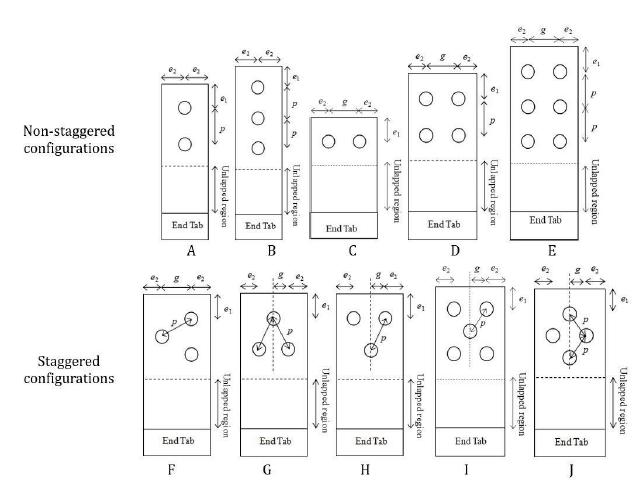
Ten multi-bolts configurations were implemented in current work as given in Table 1 comprised of five non-staggered and five staggered configurations. Circular holes of 5 mm diameter, d was drilled with end distance, e 1 and edge distance, e 2 were respectively set constant to 3d and the normalised pitch distance, p is 4d following minimum spacing provisions specified in code of practice (American Institute of Timber Construction, 2005American Institute of Timber Construction, (2005). Timber Construction Manual. Fifth edition, John Wiley & Sons, Hoboken, New Jersey 239-269.). Spacings between adjacent holes were given as symbol p and g respectively as illustrated in Figure 1. Un-lapped region of 70mm was provided to allow the elastic deformation on the plates. Fastener systems were used of steel M5 hex socket screw cap head allen bolts with high tensile grade 12.9.
A total of 30 WKRP testing plates were prepared throughout the testing series. Three sets of testing plates were prepared and standard deviations of less than 5% within tested datasets were taken to produce good reproducibility. Single-lap multi-bolts configurations assemblies and aluminium plates with a thickness of 4 mm as shown in Figure 2 were used as joining plate. The plate has yield strength of 100MPa to avoid permanent deformation in aluminium plate to allow repetitive use. End-tab of 50mm was prepared to provide proper gripping and avoid slippage to occur during mechanical testing. Mechanical testing was carried out under quasi-static tensile loading using a Universal Testing Machine (UTM) Instron machine with 50 kN load cell and crosshead speed of 0.2 mm/min. The joint configurations were tested immediately after applying bolt preload (using torque wrench) to avoid bolt relaxation effects. A spacer was placed at end tab during mechanical testing to avoid primary bending during mechanical testing. In single-lap joint configurations, secondary bending phenomenon is unavoidable to give additional tensile stresses and may decrease the joint strength (Smith et al., 1986Smith, P.A., Pascoe, K.J., Polak, C., and Stroud, D.O., (1986). The Behaviour of Single-lap Bolted Joints in CFRP Laminates. Composite Structures 41-55.). Nevertheless, the secondary bending effects does not give significant change in load displacement curve but slightly reduce tensile strength compared to double-lap joints configurations.
3 FINITE ELEMENT MODELLING
3.1 Pre-processing stage
A 3-D modelling was adopted in current work to incorporate bolt preload, surface interactions and secondary bending. Three-dimensional modelling frameworks were modelled as half-model (except configuration F due to no existence of symmetrical axis) following experimental configurations of single-lap multi-bolted joints to reduce computational time and effort. The models were explicitly modelled out-of-plane effect including frictional load transfer, bolt clamp-up and surface interactions. The boundary conditions at far-left edge were assigned as fixed boundary and applied displacement was assigned at the far-right edge as shown in Figure 3. Bear in mind that top plate is WKRP plate and bottom plate is aluminium following experimental configuration assemblies (placing WKRP as top plate also to avoid contact with threaded region within the bolt shaft).
Y-symmetry was assigned at the y-axis to portray half-model configurations. Surface interactions were modelled as “master-slave” interactions where master surface was assigned in materials of larger modulus (exhibited less deformable) and slave surface assigned in relatively weaker surface materials. Friction coefficients between composite-composite (0.3) and composite-steel/composite-aluminium (0.1) were assigned similar to McCarthy et al. (2005McCarthy, C.T., McCarthy, M.A., and Lawlor, V.P., (2005). Progressive Damage Analysis of Multi-bolt Composite Joints with Variable Bolt-Hole Clearances. Composite Part B - Engineering 36: 290-305.), correspondingly contact surfaces was modelled as small sliding (sliding formulation to allow significant movement of nodes) and surface-to-surface (discretization method). XFEM regions were assigned within the net-tension plane at the vicinity of outer bolt nearest to the applied loading as observed experimentally to provide fast convergence.
The mesh was refined at the vicinity of hole edge and was made coarser at distance further from notch edge to save computational efforts. The damage stabilization value of 1 x 10⁻⁵ was implemented throughout all models, similar values were used in Ahmad et al. (2014aAhmad, H., Crocombe, A.D., and Smith, P.A., (2014a). Strength Prediction in CFRP Woven Laminate Bolted Single-lap Joints Under Quasi-Static Loading Using XFEM. Composites Part A: Applied Science and Manufacturing 66: 82-93.) on bolted CFRP joints and Supar and Ahmad (2018bSupar, K., and Ahmad, H., (2018b). Multi-holes Configurations of Woven Fabric Kenaf Composite Plates: Experimental Works and 2-D Modelling. Journal of Mechanical Engineering and Sciences 12: 3539-3547.) on multi-holes WKRP composite plates. First-order brick element with element designation code of C3D8I (an 8-node linear brick, incompatible modes) was used as element type in current standard ABAQUS Version 6.13. Despite of susceptible shear locking phenomenon in brick elements type, however this effect is alleviated by applying incompatible modes, in ABAQUS given as C3D8I element.
3.2 Implementation of unified bolt preload
The procedure to assign bolt preloads were followed as suggested by ABAQUS CAE 6.13 documentation, where the bolt was assigned with pre-tensioned load prior to far-field stress applied. Two loading steps involved comprised of Step 1 (pre-loading step) which is implementation of bolt preload and Step 2 to incorporates the applied far-field stress at the far-right of WKRP plate. Physically, in order to provide efficient load transfer between joining parts, total bolt torque applied has to be sufficient to overcome plate slip so that the joining parts behave elastically and the prevailing torque was given in equation (1) below. Formerly in ESS technique, experimental sliding load is required to provide effective bolt preload and regarded as semi-empirical approach. Then, the effective bolt preload assigned in ESS technique is taken from spring analogy dependent upon bolts configurations.
Current model was implemented 3-D modelling framework with unified bolt preload (UBP) technique to provide single bolt preload value to be incorporated in FEA modelling given in equation (1) (Engineers Edge, 2018Engineers Edge (2018). Calculation Assembly Torque per ISO 68 & ISO 724. Retrieved from https://www.engineersedge.com/material_science/calculating_assembly_torque_per__iso_68__iso_724_13154.htm
https://www.engineersedge.com/material_s...
).
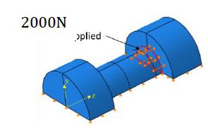
where M A, F M, p, d 2, μ G, μ K were referred as assembly torque (Nm), bolt preload (kN), pitch spacing, bolt diameter, thread friction coefficient and bearing friction coefficient respectively. In addition, expression where d w is outer diameter of bearing surface and d h is the plate hole diameter respectively and were illustrated in Figure 4. The values of parameters given in Equation (1) are given as follows: M A = 5Nm, p=0.94, d 2=5, μ G=0.3, μ K=0.3, and D Km =5.
From this equation, the preload value is calculated as 2000N and applied to each bolt in a joining plate. This value will be used throughout the testing series implemented. Similar value was also previously implemented in Ahmad et al. (2012Ahmad, H., Smith, P.A., and Crocombe, A.D., (2012). 3-D Modelling of GFRP Woven Fabric Double-Lap Bolted Joint. Asian-Australasian Conference on Composite Materials 2: 1050-1056.) of woven fabric GFRP system in single bolt joints, bear in mind that both woven-fabric composites types using epoxy resin as matrix binder. It was suggested that both systems are woven fabrics, and resin-rich (where volume fiber fraction is less than 30%), thereafter implementation of similar bolt preload is reasonable in both cases.
The procedure to assign bolt preloads were followed as suggested by ABAQUS CAE 6.13 documentation and were implementation by Supar and Ahmad (2018aSupar, K., and Ahmad, H., (2018a). Strength Predictions of Multi-Bolted Joints in Woven Fabric Kenaf Composite Plates with Different Configurations Using XFEM Frameworks. Journal Trends in Textile Engineering & Fashion Technology 2: 1-10.). The bolt preload was implemented in current models by applying pre-tension force within internal region of bolt shaft as shown in Figure 5 below. Then, the bolt preload was kept constant as traction being applied during mechanical testing.
4 RESULTS AND DISCUSSIONS
Strength predictions of current modelling framework were described respective to parametric investigated such as bolt configuration, lay-up types and plate thickness, given in sub-sections below, then compared correspondingly with former ESS technique (Supar and Ahmad, 2018aSupar, K., and Ahmad, H., (2018a). Strength Predictions of Multi-Bolted Joints in Woven Fabric Kenaf Composite Plates with Different Configurations Using XFEM Frameworks. Journal Trends in Textile Engineering & Fashion Technology 2: 1-10.).
4.1 Comparison with experimental datasets
In current study, UBP technique was carried out as an improvement technique from previous ESS modelling approach, then validated against experimental datasets. Similar net-tension crack paths were observed between UBP modelling and experimental observations as given in Figure 6. The cracks were initiated and propagated from hole edge and at certain distance ahead of hole edge gave catastrophic failure.
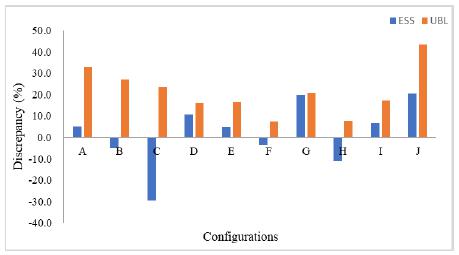
Current UBP technique applying a single bolt preload value taken from available code of practice (Engineers Edge, 2018) and was assigned to each bolt in all testing series. Good agreements were exhibited in current technique with less than 43% discrepancy (average of 20% discrepancy was found) as shown in Table 2. Most testing series was showing over-prediction value especially within staggered configurations than non-staggered counterparts, partly due to the large bolt preload in former configurations resulting from more bolts. The best agreement was given in combination of thinner and cross-ply lay-ups, where PX2 gives discrepancy of less than 21%.
4.2 Effect of bolt configurations
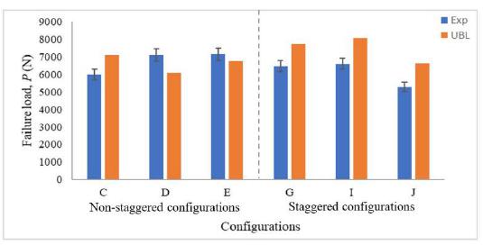
Figure 7 showed comparison of failure load of PX4 lay-ups in three non-staggered and staggered configurations respectively between experimental results and unified bolt preload (UBP) modelling. Overall, good agreements were demonstrated in all testing configurations of less than 25% discrepancy. Nevertheless, non-staggered configurations exhibited better prediction than staggered counterparts due to less contact interactions, less bearing area and not much complex stress distributions exhibited. Similar findings were reported in multi-holes configurations (Supar and Ahmad, 2018bSupar, K., and Ahmad, H., (2018b). Multi-holes Configurations of Woven Fabric Kenaf Composite Plates: Experimental Works and 2-D Modelling. Journal of Mechanical Engineering and Sciences 12: 3539-3547.) and multi-bolts configurations (Supar and Ahmad, 2018a) where more complex stress distribution may exhibit within each bolt in diagonal directions. From stress analysis study of these testing series (Supar and Ahmad, 2018c), staggered hole configurations give highest tangential stress, σ T along hole boundary than non-staggered configuration due to resistance stress diagonally may not be physically represented in current framework of using smeared-out properties.
Higher failure load in staggered configurations than non-staggered configurations resulting from requirements of plates geometries such as bolt spacings (given as gage, g and pitch, p) and bolt arrangements. Bear in mind that staggered series have wider testing plates width than non-staggered series. Distinct bolts configurations gave changes in by-pass stress distribution to be transferred to their adjacent bolts (Supar and Ahmad, 2018cSupar, K., and Ahmad, H., (2018c). Three-dimensional Stress Analysis Study on Multi-bolted Joints of Composite Plates. Journal of Engineering Science and Technology 1-11. submitted manuscript.) and correspondingly affected joint strength. Staggered configurations were designed to gives more effective usable area within neighbouring bolts with showed lengthen net-tension failure associated to “zig-zag” path, readily seen in GFRP joints (Cunningham et al., 2015Cunningham, D., Harries, K.A., and Bell, A.J., (2015). Open-hole Tension Capacity of Pultruded GFRP Having Staggered Hole Arrangement. Engineering Structures 95: 8-15.). However, staggered configurations in WKRP plates does not exhibited “zig-zag” path but showing net-tension failure plane across outer bolt (Supar and Ahmad, 2017bSupar, K., and Ahmad, H., (2017b). Stress Distribution Study on Multi-Holes Configuration in Woven Fabric Kenaf Composite Plates. IOP Conference Series: Materials Science and Engineering 127: 1-8.).
4.3 Effect of lay-ups types
Cross-ply series (PX4) exhibited better predictions than quasi-isotropic series (PQ4) of similar nominal thickness. It was found that cross-ply exhibited less than 25% discrepancy (as opposed to PQ4 of 43%), however both series showing average discrepancies of approximately 20%. Larger volume fraction of reinforcing fibers contributes to higher failure loads, where cross-ply has 50% 0° fiber angle than 25% in quasi-isotropic plates of similar plate thickness. Ultimate resistance is borne by reinforcing fibers in longitudinal direction (0° fiber angle), however WKRP plate has only about 10% volume fiber fraction and regarded as resin-rich composites. Therefore, not much effect on variation of lay-up types is much expected.
In current UBP technique, most configurations showed almost consistence discrepancies at 20% due to implementation of a single bolt preload value in each bolt. This technique is more realistic physically followed experimental work within assigned similar bolt preload value in all configurations and showing independent numerical technique where not dependent on experimental datasets than former ESS technique (Supar and Ahmad, 2018aSupar, K., and Ahmad, H., (2018a). Strength Predictions of Multi-Bolted Joints in Woven Fabric Kenaf Composite Plates with Different Configurations Using XFEM Frameworks. Journal Trends in Textile Engineering & Fashion Technology 2: 1-10.). However, quasi-isotropic lay-ups in staggered series may better resistance in shear due to existence of 45° fiber direction as maximum principal shear plane occurred in 45° angle. Staggered configurations found of diagonal direction of bolt arrangement and stress distributions were transferred mostly in diagonal directions (Supar and Ahmad, 2018c).
Cross-ply lay-ups demonstrates good agreement than quasi-isotropic series, partially due to repetitive layer sequence gives more representation of smeared-out properties in cross-ply lay-ups. Current techniques imposed a single bolt preload value applied to each bolt in both lay-up types. It is expected that hole elongation in PQ4 is higher than PX4 due to more 0° fiber volume in latter lay-up, however due to constant bolt preload associated to constant joint stiffness prior to slippage. Therefore, it is much expected that the modelling results produced less prediction strength in cross-ply lay-ups (as results of lesser hole elongation and constant bolt preload) than quasi-isotropic series as shown in Figure 8. More severely, if the holes were arranged in more rows numbers associated to more lesser hole elongations corresponds to smaller prediction loads. From modelling results, under-prediction in two-rows bolts given in configuration D and E in PX4 series is in consistence of smaller hole elongation.
4.4 Effect of plate thickness
Figure 9 showed comparison of discrepancies in UBP technique (validated against experimental datasets) between plate thickness of PX2 and PX4 with nominal thickness of 2mm and 4mm respectively. Overall, thicker plate showed under-prediction trends due to the failure path occur before the real plate strength and it might be related with bolt preload value. This bolt preload value was calculated from the equation of bolt torque (Engineers Edge, 2018) where it largely applied in single bolt and may not be applicable in multi-bolted joints. The expression effective bolt preload in multi-bolted independent of sliding load value (extracted from experimental loading profiles as formerly applied in ESS technique) was not available in any sources or standard of practice.
Respective to plate thickness, thicker plates of PX4 gives less good agreement discrepancy than PX2 lay-ups. These findings were contrary with previous works in ESS technique (Supar and Ahmad, 2018aSupar, K., and Ahmad, H., (2018a). Strength Predictions of Multi-Bolted Joints in Woven Fabric Kenaf Composite Plates with Different Configurations Using XFEM Frameworks. Journal Trends in Textile Engineering & Fashion Technology 2: 1-10.) where better agreements were showed in thicker plates of PX4 of less than 16% discrepancy than PX2 lay-ups counterparts due to current implemented of smeared-out properties more representative in thicker plates. It was found that less secondary bending effect exhibited in thicker plates as shown in Figure 10 below. As the failure occurs across the outer bolt nearest to applied loading, the effect of secondary bending is insignificant due to plate edge lifting only occurred at the other far-end. Current approach used a single bolt preload value, it is suggested that bolt preload value is dependent upon joining plate thickness, which thicker plates produced larger bolt preload to provide efficient stress transfer through friction.
4.5 Comparison between equivalent spring stiffness (ESS) technique
Former approach (ESS technique) is semi-empirical approach that requires sliding load from experimental load-displacement profile extracted from data-logger. This limit the applicability to more unified numerical approach in variation of joining parameters such as bolt configurations, lay-up types and plate thicknesses. Figure 11 shows discrepancies comparison between ESS technique and UBP technique in PQ4 lay-ups where latter technique gives less good agreement compared to former technique as clearly given in Table 2. This is due to the former technique assigned empirical bolt preload value according to bolt configurations. On the other hand, latter technique improves former approach where purely numerical predictions were imposed and this technique still provide reasonable agreement compared to experimental datasets.
It was found that in ESS technique, effective bolt preload calculated in perpendicular series yields smaller value than parallel series arrangement. It was found that smaller bolt preload in perpendicular series may not be well represented here which taken from spring stiffness analogy. Despite of widely used as stiffness calculation in dynamics structures and mechanics of materials, complex geometries in staggered configurations requires further include further geometrical considerations in spring analogy calculation such as hole spacing, plate width effects, finite hole size etc.
ESS technique gives lesser bolt preload than current approach (consistence of 2000N bolt preload) to exhibit mostly under-prediction strength to provide less out-of-plane compression beneath the washer. This corresponds to larger plate edge lifting resulting from secondary bending phenomenon in ESS technique, lower than 2000N as applied in latter technique. As smeared-out material properties were implemented, lesser secondary bending effect may provide better strength prediction as given in UBP technique.
5 CONCLUSIONS
Current approach improves ESS technique by using a constant bolt preload value rather than using curve-fitted sliding load from experimental datasets. 3-D XFEM modelling framework using UBP technique were carried out to investigate the parametric effects from bolt configurations, lay-ups types and plate thickness. In current 3-D modelling framework, effect from secondary bending, joining plates sliding, bolt tilting, applied bolt preload using single value and bearing contact were explicitly modelled, Strength prediction of multi-bolted joints were failed in net-tension mode and in-line with experimental observations. Good agreements were found in all testing series with less than ±44% discrepancy, mostly gives less than 20%. Good predictions were found in most models, particularly staggered multi-bolts configurations due to constant bolt preload value was applied in each bolt taken from available code of practice. Cross-ply lay-ups (PX2 and PX4) gave best prediction than quasi-isotropic lay-ups (PQ4), where cross-ply lay-ups more representation of smeared-out properties due to repetitive layer sequence. Good agreements in combination of thicker and cross-ply lay-ups of less than 20% discrepancy were demonstrated. This study able to be used as a unified numerical approach by using a single bolt preload value to provide reasonable accuracy. However, further work to incorporates bolt preload with the effect of joining variables such as plate thickness and bolt spacing may give better bolt preload representative need to be carried out.
References
- American Institute of Timber Construction, (2005). Timber Construction Manual. Fifth edition, John Wiley & Sons, Hoboken, New Jersey 239-269.
- Ahmad, H., Smith, P.A., and Crocombe, A.D., (2012). 3-D Modelling of GFRP Woven Fabric Double-Lap Bolted Joint. Asian-Australasian Conference on Composite Materials 2: 1050-1056.
- Ahmad, H., Crocombe, A.D., and Smith, P.A., (2014a). Strength Prediction in CFRP Woven Laminate Bolted Single-lap Joints Under Quasi-Static Loading Using XFEM. Composites Part A: Applied Science and Manufacturing 66: 82-93.
- Ahmad, H., Crocombe, A.D., and Smith, P.A., (2014b). Strength Prediction in CFRP Woven Laminate Bolted Double-lap Joints Under Quasi-Static Loading Using XFEM. Composites Part A: Applied Science and Manufacturing 56: 192-202.
- Crews, J.H., and Naik, R.A., (1986). Combined Bearing and Bypass Loading on A Graphite/Epoxy Laminate. Composite Structures, Google Scholar 6: 21-40.
- Cunningham, D., Harries, K.A., and Bell, A.J., (2015). Open-hole Tension Capacity of Pultruded GFRP Having Staggered Hole Arrangement. Engineering Structures 95: 8-15.
- Engineers Edge (2018). Calculation Assembly Torque per ISO 68 & ISO 724. Retrieved from https://www.engineersedge.com/material_science/calculating_assembly_torque_per__iso_68__iso_724_13154.htm
» https://www.engineersedge.com/material_science/calculating_assembly_torque_per__iso_68__iso_724_13154.htm - Godwin, E.W., Matthews, F.L., and Kitty, P.F., (1982). Strength of Multi-bolt Joints in GRP. Composites Joining in Fiber-Reinforced Plastics 13: 268-272.
- Kabeel, A.M., Maimí, P., González, E.V., and Gascons, N., (2015). Net-tension Strength of Double-lap Joints under Bearing-Bypass Loading Conditions using The Cohesive Zone Model. Composite Structures 119: 443-451.
- McCarthy, C.T., and Gray, P.J., (2011). An Analytical Model for The Prediction of Load Distribution in Highly Torqued Multi-bolt Composite Joints. Composite Structures 93: 287-298.
- McCarthy, C.T., McCarthy, M.A., and Lawlor, V.P., (2005). Progressive Damage Analysis of Multi-bolt Composite Joints with Variable Bolt-Hole Clearances. Composite Part B - Engineering 36: 290-305.
- McCarthy, M.A., McCarthy, C.T., and Padhi, G.S., (2006). A Simple Method for Determining the Effects of Bolt-hole Clearance on Load Distribution in Single-column Multi-bolt Composite Joints. Composite Structures 73: 78-87.
- Moës, N., Dolbow, J., and Belytschko, T., (1999). A Finite Element Method for Crack Growth Without Remeshing. International Journal for Numerical Methods in Engineering 46: 131-150.
- Smith, P.A., Pascoe, K.J., Polak, C., and Stroud, D.O., (1986). The Behaviour of Single-lap Bolted Joints in CFRP Laminates. Composite Structures 41-55.
- Supar, K., and Ahmad, H., (2017b). Stress Distribution Study on Multi-Holes Configuration in Woven Fabric Kenaf Composite Plates. IOP Conference Series: Materials Science and Engineering 127: 1-8.
- Supar, K., and Ahmad, H., (2018a). Strength Predictions of Multi-Bolted Joints in Woven Fabric Kenaf Composite Plates with Different Configurations Using XFEM Frameworks. Journal Trends in Textile Engineering & Fashion Technology 2: 1-10.
- Supar, K., and Ahmad, H., (2018b). Multi-holes Configurations of Woven Fabric Kenaf Composite Plates: Experimental Works and 2-D Modelling. Journal of Mechanical Engineering and Sciences 12: 3539-3547.
- Supar, K., and Ahmad, H., (2018c). Three-dimensional Stress Analysis Study on Multi-bolted Joints of Composite Plates. Journal of Engineering Science and Technology 1-11. submitted manuscript.
- Supar, K., and Ahmad, H., (2018d). 2-D Strength Prediction of Single-row Multi-bolted Joints Woven Fabric Kenaf Composites. International Journal of Engineering & Technology 7: 21-24.
- Xiong, Y., (1995). An Analytical Method for Failure Prediction of Multi-Fastener Composite Joints. International Journal Solids Structures 33: 4395-4409.
-
Available online: November 21, 2018.
Publication Dates
-
Publication in this collection
2019
History
-
Received
29 July 2018 -
Reviewed
13 Nov 2018 -
Accepted
17 Nov 2018