Abstract
This paper describes the experimental performance of the bolted stiffened end-plate (BSEP) and bolted flange-plate (BFP) connections using European hot-rolled profiles and built-up profiles. Four connections are designed and constructed according to FEMA-350 and are performed under cyclic loading. The influence of using different member profiles (European profiles and built-up profiles) in both the BSEP and BFP connections are examined. The obtained test results, including failure modes, hysteretic curves, ultimate moment and rotation values and panel zone extensions were reported and the performance of different connections is compared. It was found out, based on the obtained test results, that using hot-rolled or built-up profiles in the connection does not affect its global behavior.
Keywords
Experimental study; bolted stiffened end-plate connection; bolted flange-plate connection; cyclic loading; European profiles
1 INTRODUCTION
Bolted steel beam-column connections, especially end-plate types, have increased in popularity and are widely used in steel structures since the 1994 Northridge earthquake. Before the Northridge earthquake, welded unreinforced flange bolted-web (WUF-B) connection are widely used in many steel structures. After the Northridge earthquake, inspections of many steel structures show that WUF-B connection is inclined to brittle failures and fracture initiated near the backing bar of the bottom flange weld (Schneider and Teeraparbwong 2002Schneider, S.P. and Teeraparbwong, I. (2002). Inelastic behavior of bolted flange plate connections, Journal of Structural Engineering 128(4): 492-500.). Therefore, the SAC Steel Project was funded by the Federal Emergency Management Agency (FEMA) to investigate the causes of brittle failures, provide solutions, and improve connection performance. As a result, new seismic design criteria for steel moment frames known as Recommended Seismic Design Criteria for New Steel Moment Frame Buildings (FEMA 350 2000) were developed (Roeder 2002Roeder, C.W. (2002). Connection performance for seismic design of steel moment frames, Journal of Structural Engineering 128(4): 517-525.). AISC Seismic Provisions for Structural Steel Buildings (ANSI/AISC 341-16 2016) have also been significantly revised. Nowadays, Prequalified Connections for Special and Intermediate Steel Moment Frames for Seismic Applications (ANSI/AISC 358-16 2016) explains design and calculations of post-Northridge connections. In Turkey, six post-Northridge connections are taken from FEMA-350 and they are published in Specification for Buildings to be Built in Seismic Zones (DBYBHY-2007 2007) referring on FEMA 350 (2000). Additionally, European profiles are generally used for steel framed buildings in Turkey. Thus, experimental testing the connections which are constructed with European profiles is a necessity.
Several experimental studies have been performed for bolted end-plate and bolted flange-plate connections. Tsai and Popov (1990Tsai, K.C. and Popov, E.P. (1990). Cyclic behavior of end-plate moment connections, Journal of Structural Engineering 116(11): 2917-2930.) tested three end-plate connections under cyclic loading in order to investigate the effects of rib stiffeners in line with the webs and stronger bolts. Yorgun and Bayramoğlu (2001Yorgun, C. and Bayramoğlu, G. (2001). Cyclic tests for welded-plate sections with end-plate connections, Journal of Constructional Steel Research 57: 1309-1320.) investigated two extended end-plate connections under cyclic loading using a short I-shaped element cut from a beam section between an end plate and a column flange. Yorgun (2002) investigated three extended end-plate connections, two of which had a short I-shaped element. Sumner and Murray (2002Sumner, E.A. and Murray, T.M. (2002). Behavior of extended end-plate moment connections subject to cyclic loading, Journal of Structural Engineering 128(4): 501-508.) examined four-bolt unstiffened and eight-bolt stiffened end-plate connections under cyclic loading as a part of the SAC Steel Project. Their test results show that extended end-plate moment connections can be designed to provide the strength, stiffness, and ductility required for use in seismic force resisting moment frames. Schneider and Teeraparbwong (2002Schneider, S.P. and Teeraparbwong, I. (2002). Inelastic behavior of bolted flange plate connections, Journal of Structural Engineering 128(4): 492-500.) studied bolted flange-plate connections under cyclic loading. In their study, they considered eight connections and compared the failure modes and moment-rotation relationships of those connections with each other. Coelho et al. (2004Coelho, A.M.G., Bijlaard, F.S.K. and da Silva, L.S. (2004). Experimental assessment of the ductility of extended end plate connections, Engineering Structures 26: 1185-1206.) tested eight extended end-plate connections with varying end-plate thicknesses and steel grades. Maggi et al. (2005Maggi, Y.I., Gonçalves, Y.M., Leon, R.T. and Ribeiro, L.F.L. (2005). Parametric analysis of steel bolted end plate connections using finite element modeling, Journal of Constructional Steel Research 61: 689-708.) studied end-plate connections under monotonic loading. They prepared six connections with varying end-plate thicknesses and bolt diameters. Guo et al. (2006Guo, B., Gu, Q. and Liu, F. (2006). Experimental behavior of stiffened and unstiffened end-plate connections under cyclic loading, Journal of Structural Engineering 132(9): 1352-1357.) studied end-plate connections under cyclic loading. They prepared six connections derived by changing end-plate thickness, the existence of end-plate stiffener, and column web stiffener. Shi et al. (2007Shi, G., Shi, Y. and Wang, Y. (2007). Behaviour of end-plate moment connections under earthquake loading, Engineering Structures 29: 703-716.) tested eight end-plate connections with varying end-plate thicknesses, bolt diameter, the existence of column web stiffener, and end plate stiffener under cyclic loading. Sato et al. (2007Sato, A., Newell, J. and Uang, C.M. (2007). Cyclic testing of bolted flange plate steel moment connections for special moment frames, Final Report to American Institute of Steel Construction, Inc., Report No. SSRP-07/10., 2008) tested three bolted flange plate steel moment connection specimens which constructed with deep beams to expand the experimental database for prequalifying the bolted flange plate connection. It was reported that, two connection specimens failed by beam flange net section. Abidelah et al. (2012Abidelah, A., Bouchaïr, A. and Kerdal, D.E. (2012). Experimental and analytical behavior of bolted end-plate connections with or without stiffeners, Journal of Constructional Steel Research 76:13-27.) studied eight end-plate connections under monotonic loading with experimental test and finite element analysis. They noticed that using end-plate rib stiffener increases moment capacity of the connection, but decreases ductility of the connection. Prinz et al. (2014Prinz, G.S., Nussbaumer, A., Borges, L. and Khadka, S. (2014). Experimental testing and simulation of bolted beam-column connections having thick extended endplates and multiple bolts per row, Engineering Structures 59: 434-447.) tested six end-plate connections under monotonic loading determined according to the number and placement of bolt in order to strengthen connection without using column web stiffeners. Culache et al. (2017Culache, G., Byfield, M. P., Ferguson, N. S. and Tyas, A. (2017). Robustness of beam-to-column end-plate moment connections with stainless steel bolts subjected to high rates of loading, Journal of Structural Engineering 143: 04017015. ) tested eight end-plate connection constructed with carbon steel bolts and stainless steel bolts. Their study shows that connections tested with stainless steel bolts showed clearly visible signs of distress prior to failure, whereas the carbon-steel-bolted equivalents provided no warning of failure prior to brittle fracture. Saberi et al. (2017Saberi, H., Kheyroddin, A. and Gerami, M. (2017). Seismic strengthening of weak bolted end plate connections using welded haunches, International Journal of Steel Structures 17(2): 743-755.) used haunch as a way to rehabilitate end-plate bolted connections with weak end plate or bolts. The results of their study show that this strengthening method improves the cyclic behavior of the weak connections.
Most of the previous studies on bolted connections, which were assessed experimentally, are constructed with built-up or wide-flange (W) profiles. There are very few studies on bolted connections concerning European profiles. Moreover, there are insufficient experimental studies concerning bolted flange-plate connections, which are constructed with any profiles.
The aim of this study is to experimentally assess and comparison of bolted stiffened end-plate (BSEP) and bolted flange-plate (BFP) connections under cyclic loading, which are constructed with European profiles and built-up profiles, using new examples compatible with DBYBHY-2007.
2 EXPERIMENTAL PROGRAM
Experimental studies of bolted stiffened end-plate and bolted flange-plate connections under cyclic loading are presented. For each connection, two specimens are designed and tested, with hot-rolled profiles and built-up profiles, respectively. Tested connections and their abbreviations are given in Table 1.
2.1 Geometric properties of the connections
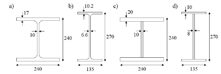
BSEP-01 and BFP-01 are constructed with IPE270 beams and HE240B columns which are European profiles. Height and width values of the built-up beam and column members are taken same as with those of the connections which is constructed with hot-rolled profiles. The connections are designed according to FEMA-350 and in accordance with DBYBHY-2007 to ensure the minimum requirements such as joint strength, bolt diameter, end-plate and flange-plate dimensions. The dimensions of the hot-rolled and built-up profiles are shown in Figure 1.
The dimensions of the hot-rolled and built-up profiles; a) HE240 columns, b) IPE270 beams, c) built-up columns, d) built-up beams.
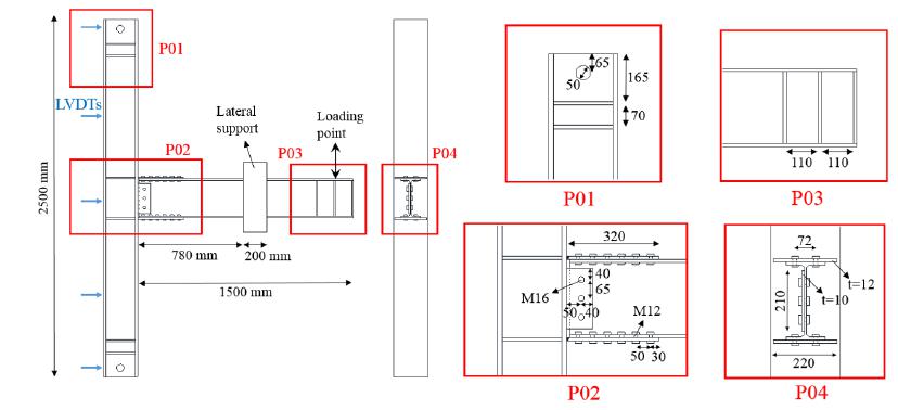
General configurations, details, and some instrumentations of the BSEP and BFP connections are shown in Figures. 2 and 3, respectively. The BSEP connections consist of two parts, one of which is an end-plate with a thickness of 40 mm, which is welded to the beam and fixed to the column flange with sixteen M16 slip-critical bolts. The other part consists of two end-plate rib stiffeners with a thickness of 8 mm welded to the beam flange and end-plate. The dimensions of the rib stiffeners are designed in accordance with FEMA-350 and DBYBHY-2007. The slope of the rib stiffener is considered 29° as seen in Figure 2. Different dimensions and slope of the rib stiffener have been studied by Tartaglia et al. (2018Tartaglia, R., D'Aniello, M. and Landolfo, R. (2018). The influence of rib stiffeners on the response of extended end-plate joints, Journal of Constructional Steel Research 148: 669-690.). The BFP connections also consist of two parts, one of which is two flange plates with a thickness of 12 mm welded to the column flange and fixed to the beam flange with twelve M12 slip-critical bolts. The other part is a web-plate with a thickness of 10 mm welded to the column flange and fixed to the beam-web with three M16 bearing-type bolts. Bolt hole diameters are considered to be standard-size hole and are presented in Table 2.
2.2 Test setup and instrumentations
To support the connections, supporting members which consist of double U240 profiles extending from the upper end of the column to the floor are used on both sides and behind of the column. A connection apparatus is designed and used to connect these supporting members to the upper end of the column. Pins with a diameter of 50 mm is used to connect the apparatus to the upper end of the column and to connect the lower end of the column and supporting members to the floor. The general configuration of the supporting members with the connection BSEP-01 is shown in Figure 4.
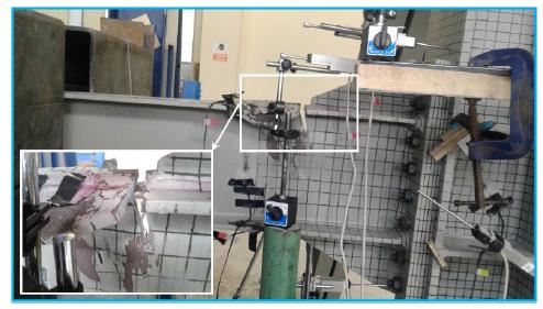
As seen in Figure 5(a), a two-way actuator having 500 kN tension and 1000 kN compression capacity is used to apply the cyclic load at the beam tip in the vertical plane. A connection apparatus is designed and used to connect the actuator to the beam tip. As seen in Figure 5(b), a steel cylinder member is used in this apparatus to avoid lateral reaction force at the actuator. Lateral supports are used to restrain against lateral torsional buckling in the beam as seen in Figure 5(c).
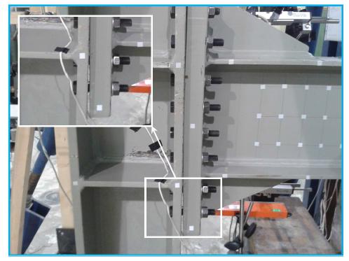
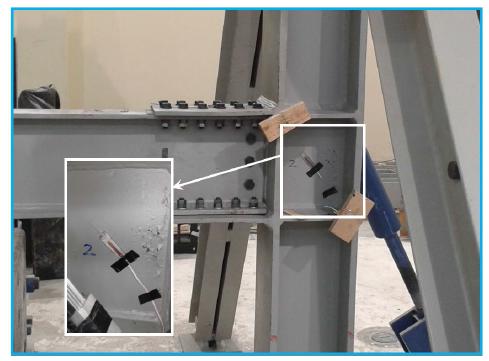
For the measurement of displacement values at certain locations of the connections, linear variable differential transformers (LVDT) are used. The LVDTs are placed on the loading point, the panel zone and behind the column at five points (see Figures 2 and 3).
2.3 Loading
The connections are tested under cyclic loading applied to the beam tip. Cyclic loading history is taken from FEMA-350 and continues end of 6% rad rotation as shown in Table 3. Additionally, before the experimental tests, pretension forces according to ANSI/AISC 360-16 (2016) are applied to the M16 bolts of the BSEP connections and M12 bolts of the BFP connections by fully tightening with an impact wrench calibrated prior to the assembly of each specimen.
The general configuration of the supporting members; a) photo in the laboratory, b) drawing.
Some equipment used in experimental tests; a) actuator, b) connection apparatus, c) lateral supports.
2.4 Materials
Two parameters were taken into account to determine materials of components of all the connections: (1) specified in relevant codes, (2) readily available in the market. S235 steel is used for end-plate and end-plate rib stiffeners for BSEP connections. Hot-rolled profiles (IPE270 and HE240B) are made from S275 steel for BSEP-01 and BFP-01. Moreover, high strength bolts (10.9 grade) are used for all the connections and the supporting members. All profiles and plates for all the connections and the supporting members which are not mentioned up to now are made by S355 steel. Due to lack of equipment in the laboratory, coupon tension tests were not performed for all the materials. Coupon tension tests were performed including following thickness of plates: 8, 10, 12, 20, and 30 mm. Three different coupon tension tests were performed for each thickness of plate. The nominal average stresses and each location of the material collected in Table 4.
3 TEST RESULTS
For all the connections, the applied cyclic loading history is reached the end of 6% rad total rotation at the beam tip. It should be noted that during all tests it is observed that the deformations of the supporting members and column are significant and cannot be ignored. Because of this, column end-point deformations caused significant column rotation. Therefore, the column rotation is subtracted from the applied rotation for each cycle to obtain rotation of the connections. Figures 6 and 7 show deformations of the columns, which are measured by LVDTs behind the columns (some LVDTs did not work and could not measure). It is observed that during the test of BSEP-02, column end-point deformations are higher than the other connections.
Column deformations through column height for the connections constructed with hot-rolled profiles; a) BSEP-01, b) BFP-01.
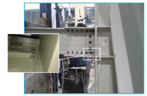
Figures. 8, 9, 10 and 11 show the connections BSEP-01, BFP-01, BSEP-02 and BFP-02 at the end of the test, respectively. In the connection BSEP-01, during the cyclic of 3.27% rad, local buckling of the beam flange is noticed. In the cyclic of 5.23% rad, the amplitude of the beam local buckling is increased and in the end of 5.40% rad fracture occurred at the beam top flange and web as seen in Figure 8. In the connection BFP-01, a component fracture is not observed at the end of the test. During the cycles of 0.81% rad, self-untightening of flange nuts are observed. Because of this, slip between flange-plate and beam-flange occurred and at the end of the test flange-plate displaced to the flange weld about 6 mm, as seen in Figure 9. In the connection BSEP-02, a component fracture is not observed at the end of the test, unlike the connection BSEP-01. During the test, self-untightening of and nuts is observed like the connection BFP-01. Thus, the end-plate opening occurred at the end of the test, as seen in Figure 10. In the connection BFP-02, double nuts are applied to prevent self-untightening of flange nuts. At the end of the test, a component fracture and slip between flange-plate and beam-plate are not observed. As seen in Figure 11, flaking of the paint in the panel zone occurred during the cycles of 4.47% rad.
Column deformations through column height for the connections constructed with built-up profiles; a) BSEP-02, b) BFP-02.
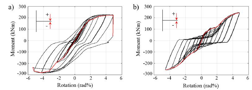
The hysteretic curves of the moment at the column face versus rotation of the connections and envelopes of these curves are presented in Figures 12 and 13. The hysteretic behavior of the each connection demonstrates that significant strength degradation is not observed during the test, except for the connection BSEP-01. Due to the fracture at the beam flange and web, in the connection BSEP-01, a huge amount of strength degradation (about five times) occurred. AISC seismic provisions requirements and also DBYBHY-2007 accept minimum 4% rad rotation capacity in a beam-column connection without any fracture or strength degradation more than 20% for special moment frames. As seen in the hysteretic curves (see Figures 12 and 13), the connections BSEP-01, BFP-01, and BFP-02 achieve minimum 4% rad rotation capacity requirement for special moment frames. For the connection BSEP-02 due to the high amount of rotation of the column, maximum rotation value reached at the end of the test is less than 4% rad. Thus, a definite comment cannot be made for the connection BSEP-02.
It was mentioned that for the connection BFP-01, slip between flange-plate and beam-flange is noticed due to self-untightening of flange nuts. Because of this, the moment value is almost constant between the rotations of 1% rad and 1.85% rad as seen in Figure 12 (b). This situation is not observed for the connection BFP-02, since self-untightening of flange nuts was not observed thanks to applying double nuts.
Moment - rotation performance for the connections constructed with hot-rolled profiles; a) BSEP-01, b) BFP-01.
Moment - rotation performance for the connections constructed with built-up profiles; a) BSEP-02, b) BFP-02.
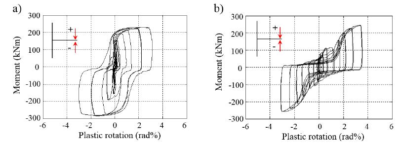
Moment at the column face versus plastic rotation of the connections are given in Figures 14 and 15. The total plastic rotation is obtained by subtracting the elastic rotations. As seen in Figure 14 and 15, plastic rotation contributions of the connections are higher than 3%, except for BSEP-02 due to high amount of rotation of the column. AISC seismic provisions requirements accept also minimum 3% rad plastic rotation capacity in a beam-column connection without any fracture or strength degradation more than 20% for special moment frames. Therefore, mentioned connections achieve also minimum 3% rad plastic rotation capacity requirement for special moment frames.
Figures 16 and 17 show the comparison of the connections constructed with hot-rolled profiles and built-up profiles, respectively, in order to have a good comparison between different connection types with same profiles and materials. As seen in Figure 16, maximum moment capacities of the connections BSEP-01 and BFP-01 are 281.8 kNm and 257.4 kNm, respectively, while maximum rotation capacities of these connections are obtained 5.40% rad and 4.81% rad with 3.14% rad and 3.52% rad plastic rotation capacities. It can be said that moment and rotation capacities of the connection BSEP-01 are 9.5% and 12.3% greater, respectively than those of the connection BFP-01, while plastic rotation capacity of the connection BFP-01 is %12 higher than that of BSEP-01. Figure 17 indicates that maximum moment capacities of the connections BSEP-02 and BFP-02 are 270.8 kNm and 278.7 kNm, respectively, while maximum rotation capacities of these connections are obtained 3.74% rad and 4.8% rad with 2.37% rad and 3.58% rad plastic rotation capacities. It is observed that in this comparison, the connection BFP-02 has more moment and rotation capacities than those of the connection BSEP-02, unlike the comparison between the connections BSEP-01 and BFP-01. Moment and rotation capacities of the connection BFP-02 are 3% and 28.3% greater, respectively than those of the connection BSEP-02, while plastic rotation capacity of the connection BFP-02 is %51 higher than that of BSEP-02.
Moment - plastic rotation performance for the connections constructed with hot-rolled profiles; a) BSEP-01, b) BFP-01.
Moment - plastic rotation performance for the connections constructed with built-up profiles; a) BSEP-02, b) BFP-02.
According to AISC seismic provisions requirements, the probable plastic moment at the location of the plastic hinge shall be calculated by Equation 1.
Here, Cpr is a factor (are considered 1.1) to account for the peak connection strength, including strain hardening, local restraint, additional reinforcement and other connection conditions and Ry (are considered 1.1) is the ratio of the expected yield stress to the specified minimum yield stress of that material. Zef and Fy are the effective plastic modulus (484 cm3 for the IPE270 beam, 476 cm3 for the built-up beam) of the beam at the location of the plastic hinge and the specified minimum yield stress of the material (are considered 27.5 kN/cm2 for S275 steel, 38.6 kN/cm2 for S355 steel) of the yielding element, respectively. Equation 1 gives plastic moment with values of 161.1 kNm for BSEP-01 and BFP-01 and 222.3 kNm for BSEP-02 and BFP-02. Obtained test results show that moment values of the connection BSEP-01, BFP-01, BSEP-02 and BFP-02 are higher than probable plastic moment about 74.9%, 59.8%, 21.8% and 25.4%, respectively. This may result from obtained value of Cpr in the experimental tests is quite higher than the considered value. Same situation was observed in the study conducted by Nia et al. (2013).
Figures 18 and 19 show the panel zone strain versus moment of the tested connections. It is found that panel zone strain of the connection BSEP-01 is considerably insignificant when compared with the other connections. This situation can be explained with the local buckling on the flanges of the beam. Additionally, it is observed that the connection constructed with built-up profiles show more panel zone strain than the connections constructed with hot-rolled profiles.
Panel zone extension versus moment for the connections constructed with hot-rolled profiles; a) BSEP-01, b) BFP-01.
Panel zone extension versus moment for the connections constructed with built-up profiles; a) BSEP-02, b) BFP-02.
4 CONCLUSIONS
In this study, BSEP and BFP connections which are constructed with European hot-rolled profiles and built-up profiles are investigated. Based on this research study, the key conclusions drawn from the experimental studies are:
For the connections which are constructed with hot-rolled profiles, the connection BSEP-01 has more moment and rotation capacity compared with the connection BFP-01. However, when the connections which are constructed with built-up profiles are compared with each other, it is obtained that, the connection BFP-02 has more moment and rotation capacity than those of the connection BSEP-02.
Only in the connection BSEP-01 local buckling on the flanges and fracture take place. Additionally, this connection shows considerably insignificant panel zone extension when compared with the other connections. It is thought that these situations may related to each other.
Performance of the connection is not significantly affected with constructing the connections with BSEP or BFP when are considered moment and rotation capacities.
It is obtained that, using European profiles for the construction of the mentioned connection examples is suitable. A definite comment can be made for the performing more examples. Additionally, it can be said that using hot-rolled or built-up profiles in the connection does not affect the global behavior of the connection.
Acknowledgments
“This work was supported by Research Fund of the Yildiz Technical University. Project Number: 2015-05-01-KAP02”.
References
- Abidelah, A., Bouchaïr, A. and Kerdal, D.E. (2012). Experimental and analytical behavior of bolted end-plate connections with or without stiffeners, Journal of Constructional Steel Research 76:13-27.
- ANSI/AISC 341-16 (2016). Seismic Provisions for Structural Steel Buildings, AISC, Chicago, IL.
- ANSI/AISC 358-16 (2016). Prequalified Connections for Special and Intermediate Steel Moment Frames for Seismic Applications, AISC, Chicago, IL.
- ANSI/AISC 360-16 (2016). Specification for Structural Steel Buildings, AISC, Chicago, IL.
- Coelho, A.M.G., Bijlaard, F.S.K. and da Silva, L.S. (2004). Experimental assessment of the ductility of extended end plate connections, Engineering Structures 26: 1185-1206.
- Culache, G., Byfield, M. P., Ferguson, N. S. and Tyas, A. (2017). Robustness of beam-to-column end-plate moment connections with stainless steel bolts subjected to high rates of loading, Journal of Structural Engineering 143: 04017015.
- DBYBHY-2007 (2007). Specification for Buildings to be Built in Seismic Zones (in Turkish), Official Gazette of the Republic of Turkey.
- FEMA 350 (2000). Recommended Seismic Design Criteria for New Steel Moment-Frame Buildings, Federal Emergency Management Agency.
- Guo, B., Gu, Q. and Liu, F. (2006). Experimental behavior of stiffened and unstiffened end-plate connections under cyclic loading, Journal of Structural Engineering 132(9): 1352-1357.
- Maggi, Y.I., Gonçalves, Y.M., Leon, R.T. and Ribeiro, L.F.L. (2005). Parametric analysis of steel bolted end plate connections using finite element modeling, Journal of Constructional Steel Research 61: 689-708.
- Nia, Z.S., Ghassemieh, M. and Mazroi, A. (2013). WUF-W connection performance to box column subjected to uniaxial and biaxial loading, Journal of Constructional Steel Research 88:90-108.
- Prinz, G.S., Nussbaumer, A., Borges, L. and Khadka, S. (2014). Experimental testing and simulation of bolted beam-column connections having thick extended endplates and multiple bolts per row, Engineering Structures 59: 434-447.
- Roeder, C.W. (2002). Connection performance for seismic design of steel moment frames, Journal of Structural Engineering 128(4): 517-525.
- Saberi, H., Kheyroddin, A. and Gerami, M. (2017). Seismic strengthening of weak bolted end plate connections using welded haunches, International Journal of Steel Structures 17(2): 743-755.
- Sato, A., Newell, J. and Uang, C.M. (2007). Cyclic testing of bolted flange plate steel moment connections for special moment frames, Final Report to American Institute of Steel Construction, Inc., Report No. SSRP-07/10.
- Sato, A., Newell, J. and Uang, C.M. (2008). Cyclic behavior and seismic design of bolted flange plate steel moment connections, Engineering Journal 45(4): 221-232.
- Schneider, S.P. and Teeraparbwong, I. (2002). Inelastic behavior of bolted flange plate connections, Journal of Structural Engineering 128(4): 492-500.
- Shi, G., Shi, Y. and Wang, Y. (2007). Behaviour of end-plate moment connections under earthquake loading, Engineering Structures 29: 703-716.
- Sumner, E.A. and Murray, T.M. (2002). Behavior of extended end-plate moment connections subject to cyclic loading, Journal of Structural Engineering 128(4): 501-508.
- Tartaglia, R., D'Aniello, M. and Landolfo, R. (2018). The influence of rib stiffeners on the response of extended end-plate joints, Journal of Constructional Steel Research 148: 669-690.
- Tsai, K.C. and Popov, E.P. (1990). Cyclic behavior of end-plate moment connections, Journal of Structural Engineering 116(11): 2917-2930.
- Yorgun, C. and Bayramoğlu, G. (2001). Cyclic tests for welded-plate sections with end-plate connections, Journal of Constructional Steel Research 57: 1309-1320.
- Yorgun, C. (2002). Evaluation of innovative extended end-Plate moment connections under cyclic loading, Turkish Journal of Engineering and Environmental Sciences 26: 483-492.
-
Available online: January 28, 2019.
Publication Dates
-
Publication in this collection
2019
History
-
Received
17 May 2018 -
Reviewed
02 Jan 2019 -
Accepted
24 Jan 2019