Abstract
In this study, a new sub-parametric strip element is developed to simulate the axially loaded composite cylindrical panel with arbitrary cutout. For this purpose, a code called SSFSM is developed in FORTRAN to analyze the buckling of panels. The first order shear deformation theory is used to form the strain-displacement relations. Spline and Lagrangian functions are used to derive element shape functions in the longitudinal and transverse directions, respectively. The computational cost of the SSFSM is decreased dramatically, as mapping functions of the strip element are very simple. The results obtained from the SSFSM are compared with those of the literature and the results obtained by ABAQUS to show the validity of the proposed approach. A parametric study is performed to show the capability of the SSFSM in calculating the panel buckling load. Results indicate that increasing the panel thickness and panel central angles cause an increase in panel buckling load. The cutout shape is an important factor influencing the panel buckling load. For instance, when the angle between the direction of big chord of the elliptical cutout and compressive load direction are 0 and 90 degrees, the panel buckling load reaches its minimum and maximum magnitude, respectively.
Keywords:
Composite; perforated cylindrical panel; spline finite strip; sub-parametric
1 INTRODUCTION
In the recent decades, plates and cylindrical composite panels with and without holes are used widely in the aerospace, civil and mechanical industries (Shuohui et al. 2016aShuohui, Y., Tiantang, Y., Tinh, Q.B., Peng, L., Sohichi, H., (2016a). Buckling and vibration extended isogeometric analysis of imperfect graded Reissner-Mindlin plates with internal defects using NURBS and level sets. Computers & Structures 177: 23-38.-bShuohui, Y., Tinh, Q.B., Shifeng, T., Satoyuki, T., Sohichi, H., (2016b). NURBS-based isogeometric analysis of buckling and free vibration problems for laminated composites plates with complicated cutouts using a new simple FSDT theory and level set method. Thin-Walled Structures 101: 141- 156., Nejati et al. 2017Nejati, M., Dimitri, R., Tornabene, F., Hossein Yas, M. (2017). Thermal buckling of nanocomposite stiffened cylindrical shells reinforced by Functionally Graded Wavy Carbon Nano-Tubes with temperature-dependent properties. Applied Science 7: 1-24., Asadi and Qatu 2013Asadi, E., Qatu, M.S., (2013). Free vibration of thick laminated cylindrical shells with different boundary conditions using general differential quadrature. Journal of Vibration and Control 19: 356-366., Khalfi et al. 2014Khalfi, Y., Houari, M.S.A., Tounsi, A., (2014). A refined and simple shear deformation theory for thermal buckling of solar functionally graded plates on elastic foundation. International Journal of Computational Methods 11: 1350077., Khetir et al. 2017Khetir, H., Bouiadjra, M.B., Houari, M.S.A., Tounsi, A., Mahmoud, S.R., (2017). A new nonlocal trigonometric shear deformation theory for thermal buckling analysis of embedded nanosize FG plates. Structural Engineering and Mechanics 64: 391-402., Asadi et al. 2012). In this matter, buckling analysis of these structures under different load cases has been investigated by several researchers using different methods (Tiantang et al. 2017Tiantang, Y., Shuohui, Y. Tinh, Q.B., Chen, L., Nuttawit W., (2017). Buckling isogeometric analysis of functionally graded plates under combined thermal and mechanical loads. Composite Structures 162: 54-69., Tiantang et al. 2016, Patel et al. 2006Patel, B.P., Singh, S., Nath, Y., (2006). Stability and nonlinear dynamic behaviour of cross-ply laminated heated cylindrical shells. Latin American Journal of Solids and Structures 3: 245- 261., Vuong and Dung 2017Vuong, P.M., Dung, D.V., (2017). Nonlinear analysis on buckling and postbuckling FGM imperfect cylindrical shells filled inside by elastic foundations in thermal environment using TSDT. Latin American Journal of Solids and Structures 14: 950- 977., Soltani et al. 2019Soltani, K., Bessaim Houari, M.S.A., Kaci, A., Benguediab, M., Tounsi, A., Alhodaly, M., (2019). A novel hyperbolic shear deformation theory for the mechanical buckling analysis of advanced composite plates resting on elastic foundations. Steel and Composite structures 30:13-29., Asadi and Qatu 2013). Magnucki and Mackiewicz (2006Magnucki, K., Mackiewicz, M., (2006). Elastic buckling of an axially compressed cylindrical panel with three edges simply supported and one edge free. Thin-Walled Structures 44: 387-392.) investigated the effects of panel boundary conditions on the elastic buckling of composite cylindrical panel. In their research, an analytical approach was used to calculate the buckling load of a panel without any cutout. Effects of rectangular and circular cutouts on the buckling load of laminated plate were investigated analytically by Masia et al (2005Masia, U., Avalos, D.R., Laura, P.A.A., (2005). Displacement amplitudes and flexural moments for a rectangular plate with a rectangular cutout under a uniformly distributed static load. Journal of Sound and Vibration 280: 433-442.) and Ashrafi et al (2013Ashrafi, H., Asemi, K., Shariyat, M., (2013). A three dimensional boundary element stress and bending analysis of transversely/longitudinally graded plates with circular cutouts under biaxial loading. European Journal of Mechanics A Solids 42: 344-357.), respectively. Although analytical approaches are simple to calculate the buckling load, but they have some limitations such as cutout shape, panel boundary conditions and the structure shape. To overcome these limitations, the Finite Element Method (FEM) was used extensively to calculate the buckling load of composite cylindrical panels. Anil et al (2007Anil, V., Upadhyay, C.S. and Iyengar, N.G.R., (2007). Stability analysis of composite laminate with and without rectangular cutout under biaxial loading. Composite Structures 80: 92-104.) evaluated the effect of rectangular cutout on the critical load of composite plate using FEM. The influence of circular cutout on the buckling load of laminated plate was investigated by Komur and Sonmez (Komur and Sonmez 2008Komur, M.A., Sonmez, M., (2008). Elastic buckling of rectangular plates under linearly varying in-plane normal load with a circular cutout. Mechanics Research Communucations 35: 361-371.). The effects of cutouts with various shapes (such as circular and elliptical shapes) on the buckling load of composite plates were also evaluated by FEM in the several researches (Arbelo et al. 2015Arbelo, M.A., Herrmann, A., Castro, S.G.P., Khakimova, R., Zimmermann, R., Degenhardt, R., (2015). Investigation of Buckling Behavior of Composite Shell Structures with Cutouts. Applied Composite Materials 22: 623-636., Shuohui et al. 2015, Thinh et al. 2016Thinh, T.I., Tu., T.M., Quoc, T.H., Long, N.V., (2016). Vibration and buckling analysis of functionally graded plates using new eight-uknown higher order shear deformation theory. Latin American Journal of Solids and Structures 13: 456- 477., Rajanna et al. 2016Rajanna, T., Banerhee, S., Desai, M.Y., (2016). Effects of partial loading and fiber configuration on vibration and buckling characteristics of stiffened composite plates. Latin American Journal of Solids and Structures 13: 854- 879., Soni et al. 2013Soni, G., Singh, R., Mitra, M., (2013). Buckling behavior of composite laminates (with and without cutouts) subjected to non-uniform in-plane loads. International Journal of Structural Stability and Dynamics 13: 1-20., Pascan et al. 2012Pascan, O.Z., Wei-hong, Z., Ponthot, J.P., (2012). Mechanical buckling analysis of composite panels with/without cutouts. International Journal of Plant Engineering Management 17: 65-76.).
Use of the Finite Strip Method (FSM) is simpler and more economical compared to the FEM, in order to analyze long thin-walled structures such as cylindrical panels (Mirzaei et al. 2015Mirzaei, S., Azhari, M., Bondarabady Rahimi, H.A., (2015). On the use of finite strip method for buckling anaylsis of moderately thick plate by refined plate theory and using new types of functions. Latin American Journal of Solids and Structures 12: 561- 582., Fazilati 2017Fazilati, J., (2017). Stability analysis of variable stiffness composite laminated plates with delamination using Spline FSM. Latin American Journal of Solids and Structures 14: 528- 543., Balogh and Logo 2015, Rondal 1998Rondal, J., (1998). Coupled Instabilities in Metal Structures: Theoretical and Design Aspects, Springer publisher, New York, USA.). Moreover, while in the FEM the structure is discretized in transverse and longitudinal directions, it is only discretized in transverse direction in FSM (Rondal 1998). FSM can be divided into two categories. In the first one, called semi-analytical FSM, the longitudinal shape function of strip element is considered as harmonic function. Also, the transverse shape function of strip element is considered as polynomial function. Buckling load of laminated plates without any cutout subjected to different load cases was evaluated using semi-analytical FSM (Yao et al. 2015Yao, L.K., He, B., Zhang, Y., Zhou, W., (2015). Semi-analytical finite strip transfer matrix method for buckling analysis of rectangular thin plates. Mathematical Problems in Engineering 15: 1-11., Ovesy et al. 2015Ovesy, H.R., Totounferoush, A., Ghannadpour, S.A.M., (2015). Dynamic buckling analysis of delaminated composite plates using semi-analytical finite strip method. Journal of Sound and Vibration 343: 131-143., Dawe et al. 1995Dawe, D.J., Wang, S., Lam, S.S.E., (1995). Finite strip analysis of imperfect laminated plates under end shortening and normal pressure. International Journal for Numerical Methods in Engineering 38: 4193-4205., Ovesy and Fazilati 2012b). Semi- analytical FSM is very useful and efficient for buckling analysis of laminated plate when the boundary conditions of both ends of strip elements are simply supported (Wang et al. 1998Wang, S., Chen, J., Dawe, D.J., (1998). Linear transient analysis of rectangular laminates using spline finite strips. Composites Structures 41: 57-66., Dawe and Wang 1994, Cheung and Tham 1997Cheung, Y.K., Tham, L.G. (1997). The Finite Strip Method, CRC Press, New York, USA.). The longitudinal harmonic shape functions of strip element are complicated in case of more complex plate/panel boundary conditions (Wang et al. 1998, Dawe and Wang 1994, Cheung and Tham 1997). Spline FSM (SFSM) is used in the analysis of buckling load of plate/panel with different boundary conditions (Second category of the FSM) (Wang et al. 1998, Dawe and Wang 1994). The spline function is used as the shape function of strip element in the longitudinal direction. Au and Cheung (1996Au, F.T.K., Cheung, Y.K. (1996). Free vibration and stability analysis of shells by the isoparametric spline finite strip method. Thin-Walled Structures 24: 53-82.) investigated the free vibration and stability of shell without any cutout utilizing iso-parametric SFSM. In their work, First Order Shear Deformation plate Theory (FSDT) was used to model the shell. Fazilati and Ovesy (2013) investigated the effects of structure boundary conditions and material on the buckling load of laminated stiffened cylindrical panel with rectangular cutout. They developed a 3D model of cylindrical panel by using SFSM based on Higher order Shear Deformation Theory (HSDT). Finally, Eccher et al. (2008Eccher, G., Rasmussen, K.J.R., Zandonini, R., (2008). Elastic buckling analysis of perforated thin-walled structures by the isoparametric spline finite strip method. Thin-Walled Structures 46: 165 - 191.) evaluated the elastic buckling of perforated thin-walled structures such as cylindrical panels by iso-parametric SFSM. In their research, an iso-parametric spline finite strip element was developed based on the FSDT. The strip element shape functions of longitudinal and transverse directions have been considered as polynomial and B3 spline respectively (Eccher et al. 2008). Based on the literature, the order of mapping function of sub-parametric element is lower than that of iso-parametric element (Akin 2005Akin, J.E. (2005). Finite Element Analysis with Error Estimators, Elsevier publisher, New York, USA.) and therefore, equilibrium equations obtained in case of sub-parametric element have lower order than iso-parametric ones and could cause lower computational cost (Akin 2005).
A review of the literature reveals that there are two major limitations in buckling analysis of perforated laminated cylindrical panel. While the computational cost of sub-parametric element is lower than that of the iso-parametric element, there is no sign of considering sub-parametric SFSM in buckling analysis of perforated laminated cylindrical panel. Moreover, although the effects of single cutout on the buckling load of cylindrical panel are investigated in the literature, the effects of cutout with different shapes on the buckling load of composite laminated cylindrical panel are not compared with each other. Therefore, this paper is a response to these needs. In this regard, at first the shape and mapping functions of sub-parametric spline finite strip element are developed. Next, the displacement functions are derived. Then, the components of Jacobian matrix are calculated and based on the FSDT, the strain-displacement and stress-strain relationships are extended. According to the shape functions, the load vector of strip element is evaluated. Then, components of elastic stiffness and stability stiffness matrices of sub-parametric element are derived. Finally, according to the developed element, the elastic buckling analysis of laminated perforated cylindrical panel is carried out. To validate the results obtained in this paper, comparison are made between the results obtained in this study and those published in the literature and those obtained from commercial finite element software, namely ABAQUS (ABAQUS 2006).
2 Methodology
The cylindrical panel with arbitrary cutout is shown in Figure 1. As it is shown in Figure 1, R, B, and L represent the panel radius, width, central angle and length, respectively. The x, y and z axes are considered in the longitudinal, circumferential and radial directions of the panel, respectively. A local coordinate system is established for the panel using x, y and z axes. Based on the first order shear deformation theory and local coordinate system considered in Figure 1, five degrees of freedom () are considered for each node of the panel (Moradi et al. 2011Moradi, S., Poorveis, D., Khajehdezfuly, A., (2011). Geometrically nonlinear analysis of anisotropic laminated cylindrical panels with cut-out using spline finite strip method. Proceeding of conference on the Advances in Structural Engineering and Mechanics, Seoul, South Korea.). These degrees of freedom are shown in Figure 1. and are membrane (in-plane) displacement in x and y directions, w is the panel deflection in radial direction (out of plane), and and are the strip edge rotations about the x and y directions, respectively. According to the load vector and linear stiffness matrix of the cylindrical panel, the pre-buckling displacement vector of the panel is established. Based on the panel pre-buckling displacement vector, membrane force vector of the panel is calculated. Also, using the panel membrane force vector, the geometrical stiffness matrix is calculated. Finally, the buckling load of the cylindrical panel through the solution of linearized eigenvalue problem is calculated. A finite strip model of perforated cylindrical panel is shown in Figure 2. The process described above was carried out in a FORTAN code called Sub-parametric Spline Finite Strip Method (SSFSM) developed in this paper. All stages performed in this code are shown in Figure 3. The details of the process are described in the following sections. In this study, a sub-parametric strip element is developed to calculate the cylindrical panel axial buckling load. In this regard, some features of strip element such as shape functions, mapping functions, Jacobian matrix and stress-strain relationships are established. Based on these features, the stiffness matrix and load vector of the strip element are developed. The stiffness matrices and load vectors of strip elements are used in assemblage of global stiffness matrix and load vector of the cylindrical panel, respectively. In the tenth step of the algorithm, the calculation of for large number of degrees of freedom is very time-consuming and in the current analysis, is decomposed by the modified Cholsky method as =, in which [U] is an upper triangular matrix and [D] is a diagonal matrix (Rakotonirina 2013Rakotonirina, C., (2013). On the Cholesky method. Journal of Interdisciplinary Mathematics 12:875-882.). After that, the pre-buckling deformations [d0] can be extracted. Also, in the step 13th, the linear eigenvalue problem is solved by the inverse iteration method (Van Ness 1969Van Ness, J., (1969). Inverse iteration method for finding eigenvectors. IEEE Transactions on Automatic Control 14: 63-66.) which taking into account and as symmetric banded matrices. Several eigenvalues and their eigenvectors can be extracted using the aforementioned method.
2.1 Shape functions of strip element
The spline (Moradi et al. 2011Moradi, S., Poorveis, D., Khajehdezfuly, A., (2011). Geometrically nonlinear analysis of anisotropic laminated cylindrical panels with cut-out using spline finite strip method. Proceeding of conference on the Advances in Structural Engineering and Mechanics, Seoul, South Korea.) and four-noded Lagrangian functions (Moradi et al. 2011) are used to estimate the strip element displacement functions in the longitudinal and transverse directions, respectively. As it is indicated in Figure 4, the coordinate is considered in the transverse direction (y direction) of the strip element. The shape functions of strip element in the transverse direction are presented in equation 1. In this equation, is the Lagrangian function for jth nodal line in coordinate. is varied between -1 and +1. As it is presented in equation 1, the shape functions of strip element in the transverse direction are third degree polynomial function.
The C0 continuity is implied in the strip transverse direction (Eccher et al. 2008Eccher, G., Rasmussen, K.J.R., Zandonini, R., (2008). Elastic buckling analysis of perforated thin-walled structures by the isoparametric spline finite strip method. Thin-Walled Structures 46: 165 - 191.). Due to the use of this shape function, it is possible to impose any arbitrary boundary condition on the longitudinal strip edges. Four nodal lines are considered in the longitudinal direction of the strip element and m knots (node) are considered in each nodal line. In other word, each nodal line is divided into m sections. The spline function is used to derive the strip element displacement function in the longitudinal direction as shown in equation 2.
where, is the spline function for the ith knot in coordinate, while is varied between -1 to m+1. In Figure 5a, a spline function is drawn. For each knot (node) considered on each nodal line, a spline function is assigned. In Figure 5b, all of the spline functions considered on a nodal line are drawn. Two virtual nodes are considered outside the panel (nodes -1 and m+1 in Figure 5b) for each nodal line to apply any arbitrary boundary condition on the transverse edges of the strip element (Moradi et al. 2011Moradi, S., Poorveis, D., Khajehdezfuly, A., (2011). Geometrically nonlinear analysis of anisotropic laminated cylindrical panels with cut-out using spline finite strip method. Proceeding of conference on the Advances in Structural Engineering and Mechanics, Seoul, South Korea.). The displacement functions of the strip element are derived based on the shape functions considered in the transverse and longitudinal directions of the element (see equation 3). The displacement function presented in the equation 3, is derived based on the FSDT (Khayat et al. 2016aKhayat, M., Poorveis, D., Moradi, S., Hemmati, M. (2016a). Buckling of thick deep laminated composite shell of revolution under follower forces. Structural Engineering and Mechanics 58: 59-91.). In equation 3, is the displacement of strip element at degree of freedom Z in coordinates and , j is the number of nodal line and i is the number of knot (node) considered on the jth nodal line, is the Lagrangian function for the jth nodal line, is the spline function for ith knot, and is the unknown multiplier for the jth nodal line, ith knot and degree of freedom . Z could be considered as or .
The displacement function of the strip element is defined based on the knots. equation 3 can be expressed as equation 4 in which is strip element displacement vector, is the unknown multiplier for ith knot of jth nodal line, is the ith knot spline function and is the jth nodal line Lagrangian function. is comprised of , , , and (see equation 5).
Spline function in longitudinal direction (a) spline function (b) Spline functions for a nodal line.
2.2 Mapping functions
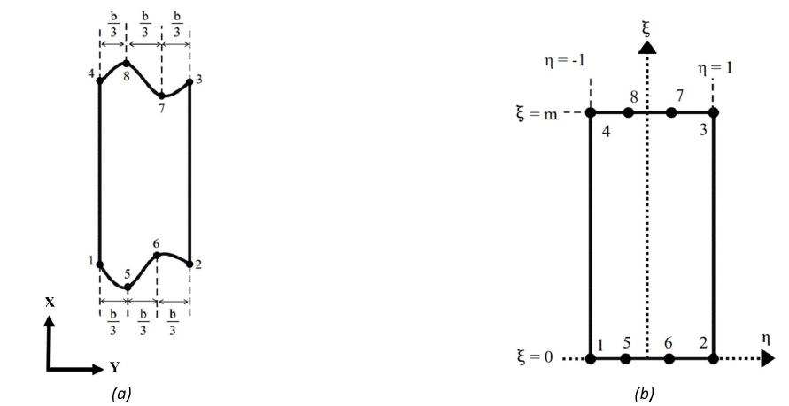
The sub-parametric strip element in the local Cartesian coordinate X and Y is shown in Figure 6a. This element is mapped into the parent element as it is shown in Figure 6b. The mapping functions are used to map the element from (X,Y) coordinate to the () coordinate system. The strip element considered in this paper has two advantages. The longitudinal edges of the strip element are linear and parallel to each other and therefore, the width of the strip (b) is constant in the longitudinal direction of the strip element. On the other hand, the transverse edges of strip element (start and end edges of the element) are defined as curved function and consequently any arbitrary cutout could be considered in the cylindrical panel. According to these advantages, the mapping functions of the strip element are estimated using eight nodes on the start and end edges of the strip element. These nodes are shown in Figure 6. In fact, the mapping functions of the element are derived based on the eight nodes while the displacement functions of the element are estimated based on the nodes. In other word, this element is a sub-parametric element (Eccher et al. 2008Eccher, G., Rasmussen, K.J.R., Zandonini, R., (2008). Elastic buckling analysis of perforated thin-walled structures by the isoparametric spline finite strip method. Thin-Walled Structures 46: 165 - 191.). x is estimated with the x-coordinate of eight nodes as equation 6. In this equation, is the mapping function of the ith node and is the x-coordinate of the ith node.
The mapping functions to are written as equation 7. The magnitude of is 1 at the ith node and 0 at the other nodes. In equation 7, m is the number of knots considered on the nodal line.
is simplified as the multiplication of two functions, and where and are functions of and , respectively (see equation 8). The constant multiplier related to the m is considered as a part of .
shape functions are cubic Lagrangian fuctions and are used to approximate boundary curve of each strip. So, each closed boundary of cutout is estimated by the several cubic polynomials. As it is illustrated in equation 6, x is proportional to , therefore and can be written as the following relations.
Same as x, the y-coordinate is estimated by eight nodes laid down on the first and last strip edges. Therefore, y can be calculated by equation 10. In this equation, i is the node number, is mapping function of the ith node and is the y-coordinate of the ith node.
Based on the advantages of the strip elements mentioned in this section of the paper, y is simplified and calculated based on the node numbers 1, 2, 3 and 4 (four corner nodes of the element). Therefore, equation 10 can be rewritten as the following equation.
where, y-coordinate of nodes 5, 6, 7 and 8 is calculated based on the y-coordinate of node number 1, 2, 3 and 4. Inserting equations 7 and 8 into equation 11, it can be simplified to get the following relation.
where, y-coordinate of strip element is estimated using four corner nodes of the element. In equation 12, is the modified mapping function of ith node. Moreover, as the width of the strip element is constant in the longitudinal direction (), therefore equation 12 can be more simplified and rewritten as equation 13.
In equation 13, is the simplified mapping function of strip element in y direction. As it is illustrated in this equation, y-coordinate of the element is estimated just with nodes number 1 and 2, and consequently y is only a function of . In other word, the simplified mapping function () in the y direction is only a function of . Thus, and of the strip element can be calculated by the following equations (see equation 14).
Therefore, the computational cost of calculation of Jacobian matrix is decreased dramatically due to the simplicity in evaluation of , , and .
2.3 Jacobian matrix
The determinant of the Jacobian matrix () is used to transform the integration from actual element to the parent element. It is calculated by equation 15 (Khayat et al. 2016aKhayat, M., Poorveis, D., Moradi, S., Hemmati, M. (2016a). Buckling of thick deep laminated composite shell of revolution under follower forces. Structural Engineering and Mechanics 58: 59-91.).
As it is shown in equation 15, the determinant of Jacobian matrix is related to the , , and terms which calculated in the previous section. Inserting equations 9 and 14 into equation 15, the determinant of the Jacobian matrix can be reached as equation 16.
where, is the width of the strip element, i is node number, is the x-coordinate of the ith node and is the mapping function of ith node (see equation 9). As it is shown in equation 16, the determinant of Jacobian matrix is only a function of . Therefore, and coordinates can be separated in the integration process to calculate the load vector, linear stiffness matrix and geometrical stiffness matrix of strip element and result in decreasing the computational cost dramatically (Khayat et al. 2016aKhayat, M., Poorveis, D., Moradi, S., Hemmati, M. (2016a). Buckling of thick deep laminated composite shell of revolution under follower forces. Structural Engineering and Mechanics 58: 59-91.). Moreover, the partial derivatives with respect to x and y coordinates are presented in equation 17.
For iso-parametric strip element used in the literature, approximation of geometry (x, y) follows the same rule as for displacement shape functions (Eccher et al. 2008Eccher, G., Rasmussen, K.J.R., Zandonini, R., (2008). Elastic buckling analysis of perforated thin-walled structures by the isoparametric spline finite strip method. Thin-Walled Structures 46: 165 - 191.). So, the geometry of iso-parametric strip element is approximated by following equations (Eccher et al. 2008).
in which coefficients and are calculated based on the geometry of each strip element. A full Jacobian matrix is derived using equation 18. Therefore, the Jacobian matrix determinant and derivatives of Jacobian matrix with respect to x and y are become dependent to and . It leads to increase the computational cost of iso-parametric strip element (available element developed in the literature) compared to that of the sub-parametric element (developed in this study).
2.4 Strain- displacement relationships
In this paper, the strain- displacement relationship is assumed to be Sanders-type (Moradi et al. 2011Moradi, S., Poorveis, D., Khajehdezfuly, A., (2011). Geometrically nonlinear analysis of anisotropic laminated cylindrical panels with cut-out using spline finite strip method. Proceeding of conference on the Advances in Structural Engineering and Mechanics, Seoul, South Korea., Khayat et al. 2016aKhayat, M., Poorveis, D., Moradi, S., Hemmati, M. (2016a). Buckling of thick deep laminated composite shell of revolution under follower forces. Structural Engineering and Mechanics 58: 59-91., Khayat et al. 2016b). As it is illustrated in equation 19, the cylindrical panel strain vector is comprised of linear part () and nonlinear part ().
The components of linear part of strain vector () are presented in equation 20 where, in this equation, , , , , , , and are the linear in-plane strain in x direction, in-plane linear strain in y direction, linear shear strain in xy plane, linear curvature strain about the x axis, linear curvature strain about the y axis, linear curvature strain in xy plane, linear shear strain in zx plane and linear shear strain in zy plane respectively. The components of nonlinear part of strain vector () are presented in equation 21 (Wang et al. 1998Wang, S., Chen, J., Dawe, D.J., (1998). Linear transient analysis of rectangular laminates using spline finite strips. Composites Structures 41: 57-66.), where , and are the nonlinear in-plane strain in x direction, nonlinear in-plane strain in y direction and nonlinear shear strain in xy plane, respectively.
The relationship between generalized linear stress vector () and linear strain vector () is presented in the following equation.
where the components of generalized linear stress vector (i.e. ) is shown by the equation 23.
In this equation, , , , , , , and are the membrane stress in x direction, membrane stress in y direction, shear membrane stress in xy plane, moment stress about y axis, moment stress about x axis, torsional stress in xy plane, transverse shear stress in xz plane and transverse shear stress in yz plane, respectively (Moradi et al. 2011Moradi, S., Poorveis, D., Khajehdezfuly, A., (2011). Geometrically nonlinear analysis of anisotropic laminated cylindrical panels with cut-out using spline finite strip method. Proceeding of conference on the Advances in Structural Engineering and Mechanics, Seoul, South Korea.).
In equation 22, is the material constitutive matrix which is expanded by equation 24. where, , and are the extensional, bending, and bending-extensional coupling rigidities respectively and can be calculated from the following relations (Moradi et al. 2011Moradi, S., Poorveis, D., Khajehdezfuly, A., (2011). Geometrically nonlinear analysis of anisotropic laminated cylindrical panels with cut-out using spline finite strip method. Proceeding of conference on the Advances in Structural Engineering and Mechanics, Seoul, South Korea.).
Note that, , and are the shear stiffness constants (Moradi et al. 2011Moradi, S., Poorveis, D., Khajehdezfuly, A., (2011). Geometrically nonlinear analysis of anisotropic laminated cylindrical panels with cut-out using spline finite strip method. Proceeding of conference on the Advances in Structural Engineering and Mechanics, Seoul, South Korea.). In equation 25, N is the number of layers, and and are the depth of lower and upper surfaces of the kth layer, respectively. Moreover, are the transformed elastic constants which are obtained from equation 26 (Eccher et al. 2008Eccher, G., Rasmussen, K.J.R., Zandonini, R., (2008). Elastic buckling analysis of perforated thin-walled structures by the isoparametric spline finite strip method. Thin-Walled Structures 46: 165 - 191., Moradi et al. 2011, Khayat et al. 2016aKhayat, M., Poorveis, D., Moradi, S., Hemmati, M. (2016a). Buckling of thick deep laminated composite shell of revolution under follower forces. Structural Engineering and Mechanics 58: 59-91.).
where, c and s stand for the and , in which is the lamination angle for each layer. are rigidities of an orthotropic layer in its material directions (1 and 2) and are calculated by the following equation.
In equation 27, , , , and are material properties which are well-known in the literature (Eccher et al. 2008Eccher, G., Rasmussen, K.J.R., Zandonini, R., (2008). Elastic buckling analysis of perforated thin-walled structures by the isoparametric spline finite strip method. Thin-Walled Structures 46: 165 - 191., Moradi et al. 2011Moradi, S., Poorveis, D., Khajehdezfuly, A., (2011). Geometrically nonlinear analysis of anisotropic laminated cylindrical panels with cut-out using spline finite strip method. Proceeding of conference on the Advances in Structural Engineering and Mechanics, Seoul, South Korea., Khayat et al. 2016aKhayat, M., Poorveis, D., Moradi, S., Hemmati, M. (2016a). Buckling of thick deep laminated composite shell of revolution under follower forces. Structural Engineering and Mechanics 58: 59-91.).
2.5 Strip element linear stiffness matrix
The linear stiffness matrix components are calculated based on the internal virtual work () done by components of the stress vector () on the strip element volume. The internal virtual work () is written as equation 28.
where is the number of ith element knots on a nodal line. The integrations on and are separated from each other because of the simplicity of Jacobian matrix determinant (see equation 16). So, the one-dimensional Gauss quadrature integration method is applied separately in each direction to compute the equation 28 (Eccher et al. 2008Eccher, G., Rasmussen, K.J.R., Zandonini, R., (2008). Elastic buckling analysis of perforated thin-walled structures by the isoparametric spline finite strip method. Thin-Walled Structures 46: 165 - 191.). In the iso-parametric element presented in the literature (Eccher et al. 2008), the determinant of Jacobian is complicated and the integrations on and are dependent to each other. This prevents of decomposition of surface integrals encountered in the calculation of stiffness matrix. It proves that the computational cost of sub-parametric strip element developed in this study is lower than that of the iso-parametric strip element due to the simplicity of its Jacobian matrix. According to the internal virtual work, the linear stiffness matrix of the strip element () is obtained from equation 29.
in which, is the strip element displacement vector (see equations 4 and 5) and is transpose of the virtual displacement vector of the panel.
2.6 Strip element force vector
There are two types of strip element based on the panel loading condition and location of the cutout on the panel. In Figure 7, a circular cutout with free edges is considered in the center of the panel. The figure shows two types of strip elements, extended strip element (i.e. ith element) and truncated strip element (i.e. jth element). The length of the extended strip element is equal to the panel length. The end edges of extended strip element are under compressive distributed load with magnitude of q. The truncated strip element is between the panel transverse edge and cutout edge; therefore, its length is less than the length of the panel. Also as can be seen from Figure 7, for the truncated strip elements only one transverse edge is under compression load of q in u direction. The external virtual work () done by compressive load applied on transverse edges of the cylindrical panel is written to obtain the load vector of the panel by the following relation (Khayat et al. 2016aKhayat, M., Poorveis, D., Moradi, S., Hemmati, M. (2016a). Buckling of thick deep laminated composite shell of revolution under follower forces. Structural Engineering and Mechanics 58: 59-91.):
In equation 30, is the total number of strip elements, is the width of ith strip element, is the length of ith strip element, is the distributed compressive load on the element edges in direction u and is the virtual displacement. For the truncated strip elements, one of the or is set to zero. Also due to the costraint on u in , equation 30 can be summerized as equation 31.
According to Figure 1, y-coordinate is along circumferential direction of the strip and can be related to the natural coordinate as:
Virtual displacement can be rewritten as equation 33 based on equation 3.
It should be noted that, three spline functions (, and ) are contributed to the external virtual work () (Eccher et al. 2008Eccher, G., Rasmussen, K.J.R., Zandonini, R., (2008). Elastic buckling analysis of perforated thin-walled structures by the isoparametric spline finite strip method. Thin-Walled Structures 46: 165 - 191.). Substituting equations 32 and 33 into equation 31 leads to following equation.
Finally, equation 30 is simplified as equation 35 to obtain the load vector of cylindrical panel.
where, and are the load vector and transpose of the virtual displacement of the cylindrical panel, respectively.
2.7 Strip geometrical stiffness matrix
An initial deflection is induced in the cylindrical panel due to the distributed compressive load applied on the edges of the panel. This pre-buckling displacement vector is calculated by the following equation.
where, is the pre-buckling displacement vector, is the panel load vector and is the linear stiffness matrix of the cylindrical panel. Based on the initial displacement vector of the panel, the pre-buckling generalized linear stress vector is obtained by equation 22. In the linearized buckling analysis it is assumed that the load-deflection relation is linear up to the onset of buckling perturbation. The stresses induced in this stage will remain constant and are independent of buckling deformations. In the geometrical nonlinear analysis which is another way to obtain buckling load of structures, the stress vector depend on the linear and nonlinear strains. This makes the problem to be nonlinear in terms of displacements. This pre-buckling bending deformations have significant effects on the calculation of the critical axial load in shells. The components of the initial generalized linear stress vector are shown in equation 37.
From the internal virtual work done by the initial linear in-plane stresses () (Khayat et al. 2016aKhayat, M., Poorveis, D., Moradi, S., Hemmati, M. (2016a). Buckling of thick deep laminated composite shell of revolution under follower forces. Structural Engineering and Mechanics 58: 59-91.), the geometrical stiffness matrix of the panel is obtained (see equation 38).
In equation 38, is the initial membrane stress in x direction, is the initial membrane stress in y direction, is the initial shear membrane stress in xy plane, is the nonlinear in-plane strain in x direction, is the nonlinear in-plane strain in y direction and is the nonlinear shear strain in xy plane. equation 38 is rewritten and simplified as equation 39.
where, is the geometrical stiffness matrix, is the displacement vector and is the virtual displacement vector of the strip element.
2.8 Buckling analysis
The linear stiffness matrix () and geometrical stiffness matrix () of the cylindrical panel are obtained by assembling linear and geometrical stiffness matrices of all strip elements. To calculate the buckling load of the panel, the eigenvalue problem presented in equation 40 is solved by the inverse iteration method (Khayat et al. 2016bKhayat, M., Poorveis, D., Moradi, S., (2016b). Buckling analysis of laminated composite cylindrical shell subjected to lateral displacement-dependent pressure using semi analytical finite strip method. Steel Composite Structures 22: 45-59.). In this equation, is the eigenvalue and is its associated eigenvector.
3 Verification
Based on the formulation presented in the previous sections, a computer program namely SSFSM, was written in FORTRAN to compute the buckling load of a cylindrical panel having cutouts with different shapes. In order to check the validity of the presented formulation, several case studies are carried out and the results obtained from SSFSM are compared with the results available in the literature and the results obtained from the ABAQUS commercial finite element software (ABAQUS 2006). The details are as follows.
3.1 Buckling load of cylindrical panel without cutout
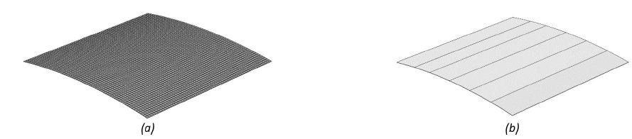
Au and Cheung (1996Au, F.T.K., Cheung, Y.K. (1996). Free vibration and stability analysis of shells by the isoparametric spline finite strip method. Thin-Walled Structures 24: 53-82.) calculated the buckling load of a square cylindrical panel without any cutout using spline finite strip method. In their research, the length of the panel, panel thickness, modulus of elasticity and poison ratio were considered as 600 mm, 5 mm, and 0.3, respectively. Moreover, all edges of the panel were simply supported. A view of the cylindrical panel considered in the Au and Cheung study is shown in Figure 8. In their research, a uniform compressive load was applied at the transverse edges of the panel. The cylindrical panel was simulated in ABAQUS using 3600 S8R5 elements and roughly 11000 degrees of freedom (ABAQUS 2006). S8R5 is an eight nodded iso-parametric shell element. In this element, the stiffness matrix is obtained using reduced integraton. A cylindrical coordinate system is defined in the ABAQUS to define/apply the boundary conditions on the panel edges. A unique uniform load is applied on the curved edge of the panel using the option named as "shell edges load" in the ABAUQS. "Buckle analysis" is performed to calculate the panel buckling load in the ABAQUS. Their panel was modeled in SSFSM with 6 strip elements, 20 sections and roughly 1900 degrees of freedom. A view of the cylindrical panel modeled in the SSFSM and ABAQUS is shown in Figure 8. The cylindrical panel buckling load for different central angle (0, 0.1, 0.2 and 0.3 radian) is calculated by SSFSM and ABAQUS. In Figure 9, the buckling load obtained from the SSFSM is compared with those of Au and Cheung (1996) and ABAQUS. As it is illustrated in the figure, as the central angle of the panel is increased, the buckling load is increased. The figure also shows that there is a good agreement between results obtained from the SSFSM and those of the Au and Cheung (1996) and ABAQUS.
Moreover, in order to verify the convergence ability of the SSFSM in calculating the panel buckling load, the buckling load of the panel for different number of strip elements and knots are calculated and presented in Table 1. As it is indicated in the table, 6 strip elements and 15 knots are sufficient for convergence of the panel buckling load.
In order to evaluate the computational cost of SSFSM, a comparsion is performed between execution time of SSFSM (sub-parametric element) and the same code with iso-parametric element. In this regrad, the panel described in this section (Figure 8) is discretized by six sub-parametric strip elements and the buckling load of the panel is calculated. Different numbers of konts are considered to simulate the panel. The execution time for both codes is measured for different degrees of freedom. The solution time of code is dependent on the number of degrees of freedom. For instance, when degrees of freedom is 2040, the solution time of SSFSM is about 148 seconds for a 2.8 GHz CPU. Figure 10 shows the computational cost of SSFSM against the iso-parametric code. In this figure, the precentage of reduction in execution time for sub-parametric element is drawn against the number of degrees of freedom. As shown in Figure 10, the execution time of SSFSM is significantly lower than that of the iso-parametric one. Two factors are responsible for drastical reduction of SSFSM computational cost. The simplicity of Jacobian determinant in the SSFSM causes decomposition of surface integral encountered in the linear elastic and geometric stiffness matrices. The number of Gauss points requried in the SSFSM to accuratly integrate the stiffness matrices is lower than those of the iso-parametric. As the degrees of freedom is increased from 675 to 2040, the precentage of reduction in the execution time is reduced from 62 to 57.5 percent. This reduction is related to the calculation of eigenvalue problem and as the degrees of freedom increases, the time to solve the eigenvalue problem increases.
3.2 Buckling load of cylindrical panel with cutout
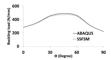
A composite cylindrical panel with layup configurations of and is simulated in ABAQUS and SSFSM. The angle layer is considered as 0, 15, 30, 45, 60, 75 and 90 degrees. The material properties of panel are presented in Table 2. The panel length, width and radius are considered 180 mm, 180 mm and 1800 mm, respectively. The ratio of thickness to length of the panel is 1/45. The panel comprises of eight layers and all edges are simply supported. The panel is under uniform compressive load on the transverse edges. A cutout with a square shape and area of 1296 was considered in the center of the panel.
The cylindrical panel was modeled in the ABAQUS with 700 of S8R5 elements type. Moreover, the panel was simulated in the SSFSM with 10 strip elements and 20 knots. ABAQUS and SSFSM models are shown in Figure 11. The buckling loads of the panel calculated from the SSFSM and ABAQUS are shown in Figures 12 and 13. As seen from Figures 12 and 13, the maximum and minimum buckling load of the panel is about 490 and 221 N/mm for layup angle 45 and 90 degree, respectively. The maximum difference between results obtained from the SSFSM and those of the ABAQUS is about 4 percent, which shows that there is a good agreement between the result obtained from the SSFSM and the ABAQUS.
4 Evaluation of SSFSM capability in calculation of panel axial buckling load
A parametric study was carried out to clarify the capability of the SSFSM in calculating the buckling load of the composite cylindrical panel with cutout. The effects of panel boundary condition, cutout shape, cutout area, panel thickness, central angle of the panel and layup angle configuration on buckling load of panel were investigated. The details are as follows.
4.1 Effect of cutout shape and panel thickness on panel buckling load
In this section, the effects of cutout shape and panel thickness are investigated on the buckling load of the panel. To this end, the effect of several cutout shapes such as square, diamond, circular and elliptical on the buckling load of the panel are investigated. All cutouts are considered in the center of the panel and their cutout area are considered to be 1296 (the ratio of cutout area to panel area is 4%). The ratio of big chord to small chord of the elliptical cutout is kept at 0.5, , 1, 1.5 and 2. The panel is simply supported on its edges and the in-plane displacements are considered to be free on all of its edges. The edges of the cutout are considered to be free of any mechanical constraint. The boundary of cutout coincides with boundaries of small strips and is approximated by eight cubic polynomials, and subsequently, 24 nodes are contributed in approximating the boundary of circular/elliptical cutout. The panel width, length and central angle are 180 mm, 180 mm and 0.3 radians, respectively. The properties of the panel material are presented in Table 2.
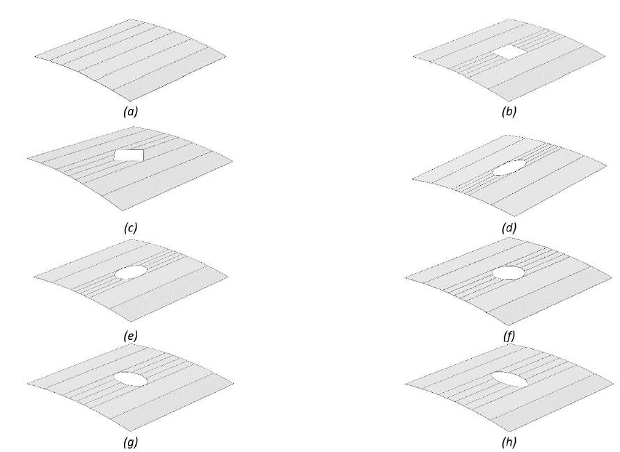
The parametric study is performed for two cross-ply layups configuration of and . Three types of panel thickness to length ratio of 1/25, 1/50 and 1/100 are used in the parametric study. The cylindrical panel is modeled in the SSFSM using 12 four-nodded strip elements and 20 knots (roughly 3700 degrees of freedom). Figure 14 shows the configuration of the panel with different cutout shapes as modeled in SSFSM. The buckling loads of the panels computed from SSFSM are tabulated in Table 3.
The results presented in Table 3 indicate that the buckling load of the panel increases as its thickness is increased. In case of the panel without any cutout, when its thickness is getting larger by 2 and 4 times, the buckling load of the panel is increased by 3.7 and 26 times, respectively. It means that the buckling load of the panel is changed nonlinearly in terms of its thickness. In all cases, buckling load of the panel with cutout is less than that of the panel without any cutout. Although all cutouts areas are the same, the cutout shape has an important effect on the buckling load.
Cylindrical panel simulated by SSFSM (a) Without cutout (b) Square cutout (c) Diamond cutout (d) Elliptical cutout with ratio of 0.5 (e) Elliptical cutout with ratio of 2/3 (f) Circular cutout (g) Elliptical cutout with ratio of 1.5 (h) Elliptical cutout with ratio of 2.
When the elliptical cutout rotates about the normal axis to the center of the panel, the buckling load varies, dramatically. In all cases, when big chord of the elliptical cutout is normal to the compressive load direction (elliptical cutout with ratio 2), the cutout has negligible effect on the buckling load of the panel compared with other cutout shapes. For these kinds of cutouts, the panel buckling load decreases by 17%, 11% and 3% for thick, medium and thin panels respectively. It indicates that when the panel thickness is decreased, the effect of cutout on changes of the panel buckling load is decreased. In most cases, when the big chord of the elliptical cutout is parallel to compressive load direction (elliptical cutout with ratio 0.5), the maximum reduction is seen in the panel buckling load. The buckling load of the panel with diamond cutout is always larger than that of the panel with square cutout. Moreover, the buckling load of the panel with square cutout is always less than that of the panel with circular cutout. As it is illustrated in Table 3, the layup configuration has an interesting influence on the buckling load of the panel. In the most cases, the buckling load of the panel with layup configuration of is more than that of configuration. But as an interesting point, when the elliptical cutouts with ratio 1.5 and 2 are considered in the center of the panel, the buckling load for layup configuration is more than that of the .
4.2 Effects of cutout size, layup, panel central angle and boundary conditions on the buckling load
In this section, the effects of cutout area, layup configuration and panel central angle are investigated on the buckling load of the panel. A circular cutout is considered at the center of the panel (see Figure 14(f)). The panel length, width and the ratio of panel thickness to its length are considered as 180 mm, 180 mm and 1/50, respectively. The panel is composed of eight layers and its material properties are presented in Table 2. The cutout area is considered as 5%, 10%, 15%, 20% and 25% of panel area. Furthermore, the central angle of the panel is considered as 0.1, 0.3 and 0.5 radian. The layup arrangements of , , , , , , and are used in the study. At the first step, the boundary conditions of the panel and cutout are the same as those used in previous section. The buckling loads of the simply supported panel calculated from the SSFSM are presented in Table 4.
The results presented in Table 4 indicate that the panel buckling load is decreased as the cutout area is increased or central angle of the panel is decreased. For instance, in case of layup and central angle of 0.1 radian, when the area contribution is changed from 5% to 25% (cutout area is increased 5 times), the buckling load of the panel is decreased from 191 to 110.7 N/m (the panel buckling load is decreased 42%). On the other hand, for the same layup and cutout area ratio of 25%, when the central angle is changed from 0.5 to 0.1 radian (central angle is decreased 5 times), the buckling load of the panel is decreased from 151 to 110.7 N/m (the panel buckling load is decreased 27%). This shows that the variation of cutout area has more effect on the buckling load than the variation of the panel central angle. The results obtained in this section indicate that the panel layup configuration is one of the most important factors on its buckling load. The panel buckling load is reached at the maximum magnitude of 707.5 N/m for cutout area ratio of 5%, central panel angle of 0.5 radian and layup configuration. While, it is reached at 639.6 and 513.3 N/m in and layup configuration, respectively, the minimum buckling load is reached at 110.6 N/m for layup configuration. As an interesting point, in case of layup and cutout area ratio of 25%, when the central angle is varied from 0.1 to 0.3, the panel buckling load is changed from 127.5 to 127.6 N/m which shows only a slight variation.
Figure 15 shows the buckling modes of laminated composite cylindrical panel having 15% central circular cutout with different layups and central angles. Panel stacking sequence is considered as [90]8, [45]8, [45/-45]4 and [0/45/90/-45]s. The central angle of the panel is 0.1 and 0.5 radians. For uni-directional layups [90]8 and [45]8 wavelength in the fiber direction is more than that of fiber transverse direction. This is pronounced with increasing in the panel central angle. The local shape of modes in these cases justifies reduction of buckling loads. The buckling mode shapes of multi-directional laminates such as [45/-45]4 and [0/45/90/-45]s behave globally and therefore endure more axial buckling loads.
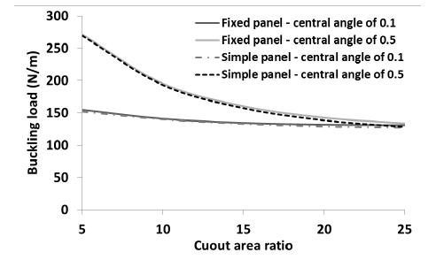
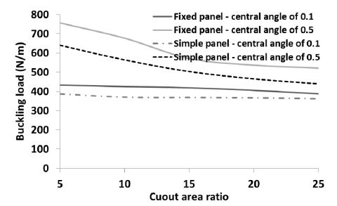
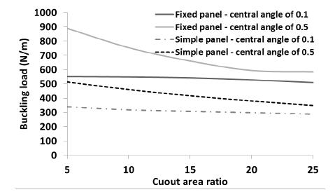
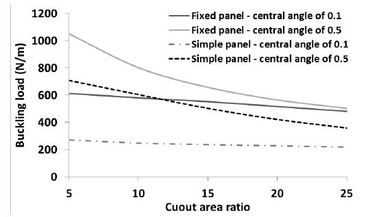
To show the capability of SSFSM to consider the effects of different cylindrical boundary conditions on the buckling load, the buckling load of the panel was calculated using SSFSM when the loading edges of the panel were fixed. The panel properties and geometry were considered as mentioned at the beginning of this section. All layups presented in Table 4 were considered in the analysis. The central angle of the panel was considered as 0.1 and 0.5 radian. The area ratio of circular cutout was considered as 5%, 10%, 15%, 20% and 25%. The buckling load of the simply supported cylindrical panel (simple panel) is compared with that of fix supported cylindrical panel (fixed panel) in Figures 16 to 23.
The buckling load of the panel with layup is shown in Figure 16. As shown in Figure 16, the buckling load of a fixed panel with layup is greater than that of simple panel. As the cutout area ratio is increased or central angle of the panel is decreased, the buckling load is decreased. The maximum buckling load of fixed panel is about 840 N/mm. In the fixed panel, the effect of central angle on the buckling load of panel decreases dramatically when cutout area ratio is increased. In the simple panel with central angle of 0.1 radians, the area of the cutout has a negligible effect on the buckling load. The buckling load of the panel with layup is presented in Figure 17. As an interesting point, the boundary condition of the panel has not considerable effect on the variation of buckling load of the panel. For instance, the maximum buckling load of the simple panel is 1% lower than that of the fixed panel. This is due to the fact that the lamination angle is perpendicular to the loading direction. The central angle of the panel has very significant effect on the buckling load. As the central angle decreases, the buckling load decreases. As the cutout area is increased, the buckling load of the panels (fixed and simple) with central angle of 0.5 radians is decreased. On the other hand, the cutout area has a slightly effect on the variation of panel buckling load with central angle of 0.1 radians. For instance, when the cutout area ratio is changed from 5 to 25%, the buckling load of the simple and fixed panels with central angle of 0.1 radians is changed about 15%. Moreover, when the cutout area ratio is reached to 25%, the effect of central angle of the panel on the buckling load of the panel is negligible. For instance, the buckling loads of fixed panel with central angle of 0.5 radian and simple panel with central angle of 0.1 radian are about 133 and 127 N/mm, respectively (in presence of a circular hole with cutout area ratio of 25%).
Cylindrical panel mode shape (a) layup [90]8 and central angle of 0.1 (b) layup [90]8 and central angle of 0.5 (c) layup [45]8 and central angle of 0.1 (d) layup [45]8 and central angle of 0.5 (e) layup [45/-45]4 and central angle of 0.1 (f) layup [45/-45]4 and central angle of 0.5 (g) layup [0/45/90/-45]s and central angle of 0.1 (h) layup [0/45/90/-45]s and central angle of 0.5.
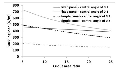
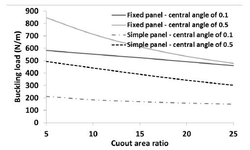
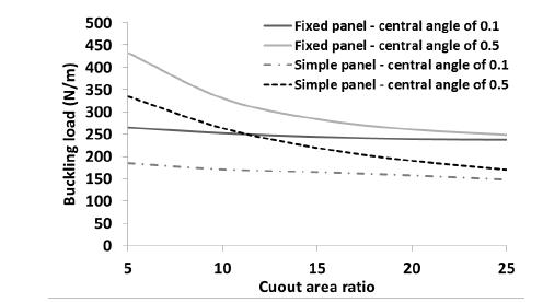
The effect of boundary condition on the buckling load the panel with layup is shown in Figure 18. As illustrated in this figure, as the cutout ratio increases, the buckling load of the panel decreases. However, when the central angle of the panel is considered as 0.1 radians, the reduction is negligible for any boundary condition. Figure 19 shows the effect of boundary condition on the buckling load for layup . The trend of variation of buckling load in this figure is same as Figure 18. The buckling loads of the fixed and simple panels with layups and are presented in Figures 20 and 21, respectively. As an interesting point depicted in Figure 20, when the central angle of the fixed and simple panels is low (0.1 radians), the cutout area has not significant effect on the buckling load of the panel. In both panels (fixed and simple), considerable difference is seen between the buckling loads of the panel with central angles of 0.1 and 0.5 radian. However, as the cutout area increases, the difference is decreased, dramatically. As shown in Figure 19 (panel with layup ), the cutout area has not a significant effect on the buckling load of the panel with central angle of 0.1 radians (fixed and simple panels). The buckling load of the panel is decreased when the central angle of the panel is 0.5 radians. When the panel layup is (Figure 22), the trend of variation of the buckling load is same as Figure 20 (layup ). The panel with Layup is reached to the maximum and minimum in comparison with other layups (Figure 23). The trend of variation of the buckling load of the panel is same as Figure 20.
5 CONCLUSION
In this paper a sub-parametric spline finite strip element is developed to study the buckling analysis of perforated composite cylindrical panel. To this end, shape, mapping and displacement functions, Jacobian matrix, strain-displacement relations based on first order shear deformation theory, load vector, and linear and geometrical stiffness matrices of the strip element were derived. The obtained eigenvalue problem was solved by inverse subspace iteration to calculate the buckling load of the cylindrical panel. All of these steps were carried out in a FORTRAN code called SSFSM. The results obtained by the SSFSM were compared with those of the published literature and those obtained from ABAQUS finite element software to check the validity of the results.
A parametric study was performed to show the influences of cutout shape and area, panel thickness, central angle of the panel, boundary conditions of the panel and layup scheme on the axial buckling load of the composite cylindrical panel. The cutouts with the shape of circle, elliptic, square and diamond were considered in the center of the panel. The ratio of big to small chords of the elliptical cutout and the ratio of circular cutout area to panel area were varied. In addition eight layup configurations (angle-ply and cross-ply), three panel thicknesses (thick, medium and thin) and three panel central angles were considered in the parametric study. The following conclusions can be extracted based on the current study.
-
- The simplicity of the Jacobian matrix in the current sub-parametric study causes the surface integrals encountered in the derivation of stiffness matrices turn into multiplication of two single variable integrals.
-
- Another advantage of current sub-parametric formulation over iso-parametric one returns to the reduction in the required number of Gauss points to accurately estimate the domain integrals.
-
- The reduction in execution time of current sub-parametric code against the standard iso-parametric formulation is about 60 percent. With increasing in panel degrees of freedom due to increasing in eigenvalue solvers contribution, this reduction is decreased slightly.
-
- Increasing in the cutout chord prependicular to the loading direction while unaltering cutout area increases the axial buckling load of cylindrical panel.
-
- Among the layups considered in the parametric study, quasi-isotropic laminate [0/45/90/-45]s and uni-directional [0]8 laminate carry the maximum and minimum axial buckling loads, respectively.
-
- Fixed or simply supported curved loaded edges of the panel have not any effect on the axial buckling load of the panel for [90]8 layup while they have the most effect in the case of [0]8 arrangement.
-
- Axial buckling mode of uni-directional laminates such as [90]8 and [45]8 has local expansion in the fibre direction and this is pronounced with increasing in the panel curvature. Unlike the uni-directional, in the multi-directional laminates like [45/-45]4 and [0/45/90/-45]s global expansion is illustrated.
References
- ABAQUS, (2006), User’s manual version 6.5. Hibbit, Karlsson & Sorensen, USA.
- Akin, J.E. (2005). Finite Element Analysis with Error Estimators, Elsevier publisher, New York, USA.
- Anil, V., Upadhyay, C.S. and Iyengar, N.G.R., (2007). Stability analysis of composite laminate with and without rectangular cutout under biaxial loading. Composite Structures 80: 92-104.
- Arbelo, M.A., Herrmann, A., Castro, S.G.P., Khakimova, R., Zimmermann, R., Degenhardt, R., (2015). Investigation of Buckling Behavior of Composite Shell Structures with Cutouts. Applied Composite Materials 22: 623-636.
- Asadi, E., Qatu, M.S., (2013). Free vibration of thick laminated cylindrical shells with different boundary conditions using general differential quadrature. Journal of Vibration and Control 19: 356-366.
- Asadi, E., Wang, W., Qatu, M.S., (2012). Static and vibration analyses of thick deep laminated cylindrical shells using 3D and various shear deformation theories. Composite Structures 94: 494-500.
- Ashrafi, H., Asemi, K., Shariyat, M., (2013). A three dimensional boundary element stress and bending analysis of transversely/longitudinally graded plates with circular cutouts under biaxial loading. European Journal of Mechanics A Solids 42: 344-357.
- Au, F.T.K., Cheung, Y.K. (1996). Free vibration and stability analysis of shells by the isoparametric spline finite strip method. Thin-Walled Structures 24: 53-82.
- Balogh, B., Logo, J. (2015). Optimization of curved plated structures with the finite strip and finite element methods. Civil Engeering Series 15: 1-10.
- Cheung, Y.K., Tham, L.G. (1997). The Finite Strip Method, CRC Press, New York, USA.
- Dawe, D.J., Wang, S., Lam, S.S.E., (1995). Finite strip analysis of imperfect laminated plates under end shortening and normal pressure. International Journal for Numerical Methods in Engineering 38: 4193-4205.
- Dawe, D.J., Wang, S., (1994). Buckling of composite plates and plate structures using the spline finite strip method. Composites Engineering 4: 1099-1117.
- Eccher, G., Rasmussen, K.J.R., Zandonini, R., (2008). Elastic buckling analysis of perforated thin-walled structures by the isoparametric spline finite strip method. Thin-Walled Structures 46: 165 - 191.
- Fazilati, J., (2017). Stability analysis of variable stiffness composite laminated plates with delamination using Spline FSM. Latin American Journal of Solids and Structures 14: 528- 543.
- Fazilati, J., Ovesy, H.R., (2013). Parametric instability of laminated longitudinally stiffened curved panels with cutout using higher order FSM. Composite Structures 95: 691-696.
- Khalfi, Y., Houari, M.S.A., Tounsi, A., (2014). A refined and simple shear deformation theory for thermal buckling of solar functionally graded plates on elastic foundation. International Journal of Computational Methods 11: 1350077.
- Khayat, M., Poorveis, D., Moradi, S., Hemmati, M. (2016a). Buckling of thick deep laminated composite shell of revolution under follower forces. Structural Engineering and Mechanics 58: 59-91.
- Khayat, M., Poorveis, D., Moradi, S., (2016b). Buckling analysis of laminated composite cylindrical shell subjected to lateral displacement-dependent pressure using semi analytical finite strip method. Steel Composite Structures 22: 45-59.
- Khetir, H., Bouiadjra, M.B., Houari, M.S.A., Tounsi, A., Mahmoud, S.R., (2017). A new nonlocal trigonometric shear deformation theory for thermal buckling analysis of embedded nanosize FG plates. Structural Engineering and Mechanics 64: 391-402.
- Komur, M.A., Sonmez, M., (2008). Elastic buckling of rectangular plates under linearly varying in-plane normal load with a circular cutout. Mechanics Research Communucations 35: 361-371.
- Magnucki, K., Mackiewicz, M., (2006). Elastic buckling of an axially compressed cylindrical panel with three edges simply supported and one edge free. Thin-Walled Structures 44: 387-392.
- Masia, U., Avalos, D.R., Laura, P.A.A., (2005). Displacement amplitudes and flexural moments for a rectangular plate with a rectangular cutout under a uniformly distributed static load. Journal of Sound and Vibration 280: 433-442.
- Mirzaei, S., Azhari, M., Bondarabady Rahimi, H.A., (2015). On the use of finite strip method for buckling anaylsis of moderately thick plate by refined plate theory and using new types of functions. Latin American Journal of Solids and Structures 12: 561- 582.
- Moradi, S., Poorveis, D., Khajehdezfuly, A., (2011). Geometrically nonlinear analysis of anisotropic laminated cylindrical panels with cut-out using spline finite strip method. Proceeding of conference on the Advances in Structural Engineering and Mechanics, Seoul, South Korea.
- Nejati, M., Dimitri, R., Tornabene, F., Hossein Yas, M. (2017). Thermal buckling of nanocomposite stiffened cylindrical shells reinforced by Functionally Graded Wavy Carbon Nano-Tubes with temperature-dependent properties. Applied Science 7: 1-24.
- Ovesy, H.R., Totounferoush, A., Ghannadpour, S.A.M., (2015). Dynamic buckling analysis of delaminated composite plates using semi-analytical finite strip method. Journal of Sound and Vibration 343: 131-143.
- Ovesy, H.R., Fazilati, J., (2012b). Parametric instability analysis of moderately thick FGM cylindrical panels using FSM. Computers and Structures 108: 135-143.
- Pascan, O.Z., Wei-hong, Z., Ponthot, J.P., (2012). Mechanical buckling analysis of composite panels with/without cutouts. International Journal of Plant Engineering Management 17: 65-76.
- Patel, B.P., Singh, S., Nath, Y., (2006). Stability and nonlinear dynamic behaviour of cross-ply laminated heated cylindrical shells. Latin American Journal of Solids and Structures 3: 245- 261.
- Rakotonirina, C., (2013). On the Cholesky method. Journal of Interdisciplinary Mathematics 12:875-882.
- Rajanna, T., Banerhee, S., Desai, M.Y., (2016). Effects of partial loading and fiber configuration on vibration and buckling characteristics of stiffened composite plates. Latin American Journal of Solids and Structures 13: 854- 879.
- Rondal, J., (1998). Coupled Instabilities in Metal Structures: Theoretical and Design Aspects, Springer publisher, New York, USA.
- Shuohui, Y., Tiantang, Y., Tinh, Q.B., Peng, L., Sohichi, H., (2016a). Buckling and vibration extended isogeometric analysis of imperfect graded Reissner-Mindlin plates with internal defects using NURBS and level sets. Computers & Structures 177: 23-38.
- Shuohui, Y., Tinh, Q.B., Shifeng, T., Satoyuki, T., Sohichi, H., (2016b). NURBS-based isogeometric analysis of buckling and free vibration problems for laminated composites plates with complicated cutouts using a new simple FSDT theory and level set method. Thin-Walled Structures 101: 141- 156.
- Shuohui, Y., Tiantang, Y., Tinh, Q.B., Shifeng, X., Sohichi, H., (2015). A cutout isogeometric analysis for thin laminated composite plates using level sets. Composite Structures 127: 152- 164.
- Soltani, K., Bessaim Houari, M.S.A., Kaci, A., Benguediab, M., Tounsi, A., Alhodaly, M., (2019). A novel hyperbolic shear deformation theory for the mechanical buckling analysis of advanced composite plates resting on elastic foundations. Steel and Composite structures 30:13-29.
- Soni, G., Singh, R., Mitra, M., (2013). Buckling behavior of composite laminates (with and without cutouts) subjected to non-uniform in-plane loads. International Journal of Structural Stability and Dynamics 13: 1-20.
- Tiantang, Y., Shuohui, Y. Tinh, Q.B., Chen, L., Nuttawit W., (2017). Buckling isogeometric analysis of functionally graded plates under combined thermal and mechanical loads. Composite Structures 162: 54-69.
- Thinh, T.I., Tu., T.M., Quoc, T.H., Long, N.V., (2016). Vibration and buckling analysis of functionally graded plates using new eight-uknown higher order shear deformation theory. Latin American Journal of Solids and Structures 13: 456- 477.
- Tiantang, Y., Tinh, Q.B., Duc, H.D., Wud, C.T., Thom, V.D., Satoyuki, T., (2016). On the thermal buckling analysis of functionally graded plates with internal defects using extended isogeometric analysis. Composite Structures 136: 684- 695.
- Van Ness, J., (1969). Inverse iteration method for finding eigenvectors. IEEE Transactions on Automatic Control 14: 63-66.
- Vuong, P.M., Dung, D.V., (2017). Nonlinear analysis on buckling and postbuckling FGM imperfect cylindrical shells filled inside by elastic foundations in thermal environment using TSDT. Latin American Journal of Solids and Structures 14: 950- 977.
- Wang, S., Chen, J., Dawe, D.J., (1998). Linear transient analysis of rectangular laminates using spline finite strips. Composites Structures 41: 57-66.
- Yao, L.K., He, B., Zhang, Y., Zhou, W., (2015). Semi-analytical finite strip transfer matrix method for buckling analysis of rectangular thin plates. Mathematical Problems in Engineering 15: 1-11.
Edited by
Editor:
Publication Dates
-
Publication in this collection
30 Sept 2019 -
Date of issue
2019
History
-
Received
01 Mar 2019 -
Reviewed
19 Aug 2019 -
Accepted
02 Sept 2019 -
Published
06 Sept 2019