Abstract
Nonlinear static response of laminated composite Elliptic Panels of Revolution Structure(s) (EPRS) having variable thickness resting on Winkler-Pasternak (W-P) Elastic Foundation is investigated in this article. Generalized Differential Quadrature (GDQ) method is utilized to obtain the numerical solution of EPRS. The first-order shear deformation theory (FSDT) is employed to consider the transverse shear effects in static analyses. To determine the variable thickness, three types of thickness profiles namely cosine, sine and linear functions are used. Equilibrium equations are derived via virtual work principle using Green-Lagrange nonlinear strain-displacement relationships. The deepness terms are considered in Green-Lagrange strain-displacement relationships. The differential quadrature rule is employed to calculate the partial derivatives in equilibrium equations. Nonlinear static equilibrium equations are solved using Newton-Raphson method. Computer programs for EPRS are developed to implement the GDQ method in the solution of equilibrium equations. Accuracy of the proposed method is verified by comparing the results with Finite Element Method (FEM) solutions. After validation, several cases are carried out to examine the effect of elastic foundation parameters, thickness variation factor, thickness functions, boundary conditions and geometric characteristic parameter of EPRS on the geometrically nonlinear behavior of laminated composite EPRS.
Keywords:
Variable thickness; Elliptic shells of revolution; Generalized differential quadrature; Winkler-Pasternak elastic foundation; Geometric nonlinearity
1 INTRODUCTION
The shells of revolution structures for their mechanical properties and good structural framework are commonly used in defense, automotive, marine and aerospace industries in the form of buildings, pressure vessles, bridges, hangar, aircraft, space stations, ships and submarines. These structures take many well-known geometrical shapes such as paraboloids, hyperboloids and ellipsoids in engineering applications. General theory of these structures can be found in related books such as by Amabili (2008Amabili, M., (2008). Nonlinear vibrations and stability of shells and plates, Cambridge University Press.), Libai and Simmonds (2005Libai, A., Simmonds, J.G., (2005). The nonlinear theory of elastic shells, Cambridge university press.), Qatu (2004Qatu, M.S., (2004). Vibration of laminated shells and plates, Elsevier.), Reddy (2004Reddy, J.N., (2004). Mechanics of laminated composite plates and shells: theory and analysis, CRC press.), Saada (2013Saada, A.S., (2013). Elasticity: theory and applications, Elsevier.), Tornabene and Fantuzzi (2014Tornabene, F., Fantuzzi, N., (2014). Mechanics of laminated Composite doubly-curvel shell structures: The generalized differential quadrature method and the strong formulation finite element method, Società Editrice Esculapio.). Many articles were published on dynamic and static behavior of shells of revolution structures. Free vibration studies on these structures includes articles published, although not limited to, by Al-Khatib and Buchanan (2010Al-Khatib, O.J., Buchanan, G.R., (2010). Free vibration of a paraboloidal shell of revolution including shear deformation and rotary inertia. Thin-walled structures 48:223-232.), Ataabadi et al. (2014Ataabadi, P.B., Khedmati, M.R., Ataabadi, M.B., (2014). Free vibration analysis of orthtropic thin cylindrical shells with variable thickness by using spline functions. Latin American Journal of Solids and Structures 11:2099-2121.), Awrejcewicz et al. (2013Awrejcewicz, J., Kurpa, L., Shmatko, T., (2013). Large amplitude free vibration of orthotropic shallow shells of complex shapes with variable thickness. Latin American Journal of Solids and Structures 10:149-162.), Tornabene (2011a, b), Tornabene et al. (2016), Tornabene et al. (2012), Wang et al. (2017aWang, Q., Cui, X., Qin, B., Liang, Q., Tang, J., (2017a). A semi-analytical method for vibration analysis of functionally graded (FG) sandwich doubly-curved panels and shells of revolution. International Journal of Mechanical Sciences 134:479-499., b, c).
In addition to free vibration behavior, static behavior of shells of revolution strcutures are also very important in designing these strcutures. Some important studies that include static behavior of these structures are reviewed as following.
Nath et al. (1985Nath, Y., Dumir, P., Bhatiaf, R., (1985). Nonlinear static and dynamic analysis of circular plates and shallow spherical shells using the collocation method. International journal for numerical methods in engineering 21:565-578.) carried out non-linear static and transient analysis of shallow shells with the collocation method. Paliwal and Srivastava (1993Paliwal, D., Srivastava, R., (1993). Nonlinear static behaviour of shallow spherical shell on a Kerr foundation. International journal of pressure vessels and piping 55:481-494.) studied on non-linear bending analysis of shallow shell on a Kerr foundation. Meek and Wang (1998Meek, J., Wang, Y., (1998). Nonlinear static and dynamic analysis of shell structures with finite rotation. Computer Methods in Applied Mechanics and Engineering 162:301-315.) presented non-linear static and dynamic analysis of shell structures considering von-Karman assumptions utilizing FEM. Jiashen (2001Jiashen, F., (2001). Static and dynamic stability for geometrically nonlinear governing equations of elastic thin shallow shells. Applied Mathematical Modelling 25:775-792.) obtained static and dynamic stability results using von-Karman nonlinear governing equations of thin shallow shells. Wei-ping and Qian (2002aWei-ping, Z., Qian, H., (2002a). Finite element displacement perturbation method for geometric nonlinear behaviors of shells of revolution overall beding in a meridional plane and application to bellow (II). Applied Mathematics and Mechanics 23:1390-1406., b) performed large deflection stress analysis of shells taking into account Sander's nonlinear geometric equations of moderate small rotation utilizing finite element formulation. Li and Chen (2004Li, Q., Chen, J., (2004). Nonlinear analysis of single-layer reticulated spherical shells under static and dynamic loads. Journal of Vibration and Control 10:731-754.) examined non-linear static and dynamic analysis of single layer shells using FEM. Duarte Filho and Awruch (2004Duarte Filho, L.A., Awruch, A.M., (2004). Geometrically nonlinear static and dynamic analysis of shells and plates using the eight-node hexahedral element with one-point quadrature. Finite Elements in Analysis and Design 40:1297-1315.) analyzed static and dynamic behavior of plates and shells with FEM. Civalek and Ulker (2005Civalek, O., Ulker, M., (2005). HDQ-FD integrated methodology for nonlinear static and dynamic response of doubly curved shallow shells. Structural Engineering and Mechanics 19:535-550.) performed the non-linear static and dynamic analysis of shallow isotropic shells utilizing harmonic differential quadrature technique under sinusoidal and step loading. Kang (2007Kang, J.-H., (2007). Field equations, equations of motion, and energy functionals for thick shells of revolution with arbitrary curvature and variable thickness from a three-dimensional theory. Acta Mechanica 188:21-37.) derived equations of motion and energy functionals taking into account linear three-dimensional theory for shells of revolution structures with variable thickness. Isoldi et al. (2008Isoldi, L.A., Awruch, A.M., Teixeira, P.R.d.F., Morsch, I.B., (2008). Geometrically nonlinear static and dynamic analysis of composite laminates shells with a triangular finite element. Journal of the Brazilian Society of Mechanical Sciences and Engineering 30:84-93.) investigated nonlinear static and dynamic response of laminate composite shallow shells with FEM. Polat and Calayir (2010Polat, C., Calayir, Y., (2010). Nonlinear static and dynamic analysis of shells of revolution. Mechanics Research Communications 37:205-209.) studied on bending and dynamic characteristics of curved shells with FEM. Bich et al. (2012Bich, D.H., Van Dung, D., (2012). Nonlinear static and dynamic buckling analysis of functionally graded shallow spherical shells including temperature effects. Composite Structures 94:2952-2960., 2013) presented buckling analysis of Functionally Graded Material (FGM) shallow thin shells considering von Karman nonlinear strains. Tornabene and Reddy (2013Tornabene, F., Reddy, J., (2013). FGM and laminated doubly-curved and degenerate shells resting on nonlinear elastic foundations: a GDQ solution for static analysis with a posteriori stress and strain recovery. J. Indian Inst. Sci 93:635-688.) carried out linear static analysis of laminated composite and FGM shells of revolution structures resting on a nonlinear elastic foundations utilizing GDQ method. Viola et al. (2013Viola, E., Tornabene, F., Fantuzzi, N., (2013). Static analysis of completely doubly-curved laminated shells and panels using general higher-order shear deformation theories. Composite Structures 101:59-93.) linear static analysis of laminated composite panels and shells of revolution using GDQ method. Arefi (2014Arefi, M., (2014). A complete set of equations for piezo-magnetoelastic analysis of a functionally graded thick shell of revolution. Latin American Journal of Solids and Structures 11:2073-2092.) conducted linaer piezo magneto elastic analysis of FGM shells of revolution having variable curvature. Zhang (2015Zhang, D.-G., (2015). Nonlinear static analysis of FGM infinite cylindrical shallow shells based on physical neutral surface and high order shear deformation theory. Applied Mathematical Modelling 39:1587-1596.) examined large displacement static analysis of FGM shallow curved shells using von Kármán nonlinear strain-displacement relationships with Ritz method. Viebahn et al. (2017Viebahn, N., Pimenta, P.M., Schröder, J., (2017). A simple triangular finite element for nonlinear thin shells: statics, dynamics and anisotropy. Computational Mechanics 59:281-297.) performed the non-linear static and dynamic analysis of thin shells using triangular finite element model. Jiammeepreecha and Chucheepsakul (2017Jiammeepreecha, W., Chucheepsakul, S., (2017). Nonlinear static analysis of an underwater elastic semi-toroidal shell. Thin-Walled Structures 116:12-18.) presented large displacement bending analysis of an underwater isotropic semi-toroidal shells using FEM. Tornabene et al. (2017a) investigated linear static response of damaged sandwich/laminated composite plates and shells of revolution using GDQ method. Tornabene et al. (2017b) examined linear static response of laminated composite shells of revolution resting on a nonlinear elastic foundation utilizing GDQ method. Shariyat and Alipour (2017Shariyat, M., Alipour, M., (2017). Analytical bending and stress analysis of variable thickness FGM auxetic conical/cylindrical shells with general tractions. Latin American Journal of Solids and Structures 14:805-843.) developed the linear static and stress analysis of FGM cylindrical/conical shells of revolution with variable thickness. Nejad et al. (2017Nejad, M.Z., Jabbari, M., Ghannad, M., (2017). A general disk form formulation for thermo-elastic analysis of functionally graded thick shells of revolution with arbitrary curvature and variable thickness. Acta Mechanica 228:215-231.) analyzed thermo-elastic behavior of FGM thick shells of revolution with variable thickness taking into account linear strain-displacement relations and higher order shear deformation theory. Shaterzadeh et al. (2019Shaterzadeh, A., Foroutan, K., Ahmadi, H., (2019). Nonlinear Static and Dynamic Thermal Buckling Analysis of Spiral Stiffened Functionally Graded Cylindrical Shells with Elastic Foundation. International Journal of Applied Mechanics 11: 1950005.) studied on large deflection static and dynamic thermal buckling analysis of FGM cylindrical shells with analytical method. Moita et al. (2019Moita, J.S., Correia, V.F., Soares, C.M.M., Herskovits, J., (2019). Higher-order finite element models for the static linear and nonlinear behaviour of functionally graded material plate-shell structures. Composite Structures 212:465-475.) presented linear and non-linear static responses of FGM shell and plate structures using FEM.
As described above, nonlinear studies on shells of revolution structures is limited and there isn't any study available on large displacement static analysis of shells of revolution having variable thickness resting on W-P elastic foundation. Also, elliptic form of shells of revolution structures is very important. Therefore, in this study geometrically nonlinear static behavior of laminated composite EPRS resting on elastic foundation is investigated considereing thickness variation. For this purpose, Green-Lagrange nonlinear strain-displacement relations are used as origionality considering deepness effect. Nonlinear equilibrium equations are expressed considering Winkler-Pasternak elastic foundation and solved using GDQ method. The effects of elastic foundation parameters, thickness variation factor, thickness functions, boundary conditions and geometric characteristic parameter on the static behavior of EPRS are analyzed in detail.
In the following sections, in Section 2 surface theory of EPRS structures are given. In Section 3, nonlinear strain theory is derived and equilibrium equations are expressed. In section 4, GDQ method is summarized. In Section 5, validation of the code developed for nonlinear static analysis is carried out. In Section 6, several examples are solved within the context of parametric study. In Section 7, conclusions derived from this study are summarized.
2 EPRS EQUATIONS
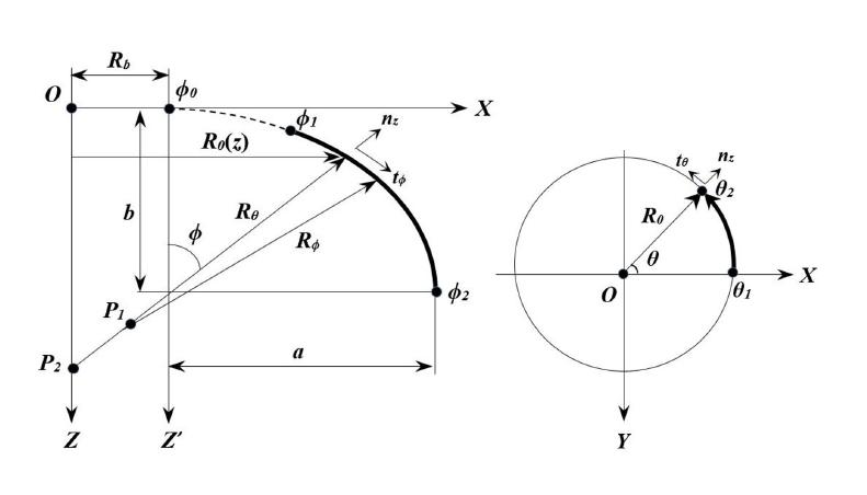
Shells of revolution is a structure defined by curved surfaces and there are many geometry types of shells of revolution (toroidal, hyperbolic, parabolic and elliptical etc.) in the literature according to their curvature characteristic. Shells of revolution geometries have been widely used in designing engineering structures such as dome roofs, aircraft hulls, nuclear reactors, aerospace structures, pressure vessel components and flat-bottom tanks. Shells of revolution with elliptic geometry is taken into account in this study. EPRS is formed by rotation of the elliptic curve as illustrated in Figure 1 about the Z axis. R b indicates the offset of the revolution axis Z with respect to the geometric central axis Z′ and R 0 is the horizontal radius. R θ and R ϕ state the principal radii of curvature for EPRS. [θ 1 , θ 2 ] and [ϕ 1 , ϕ 2 ] are the ending and starting points of the EPRS in the θ and ϕ directions, respectively.
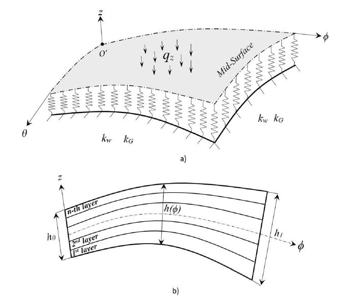
The ϕ, θ and z orthogonal coordinate system on laminated composite EPRS is illustrated in Figure 2. The meridional, circumferential and normal displacements in the ϕ, θ and z directions are stated by and , respectively.
Geometry notations of EPRS a) Loading and W-P elastic foundation b) Thickness variation of laminated composite EPRS
Geometric equations for EPRS as illustrated in Figure 1 are given in the following equation:
where b and a are the length of the semi-minor and semi-major axes of the elliptic curve, respectively. Characteristic parameter of elliptic curve can be expressed as follows (Tornabene (2011aTornabene, F., (2011a). 2-D GDQ solution for free vibrations of anisotropic doubly-curved shells and panels of revolution. Composite Structures 93:1854-1876.))
The horizontal radius R0 is
The radii of curvature Rθ and Rϕ in the circumferential and meridional directions respectively can be described as follows
2.1 Variable Thickness Functions
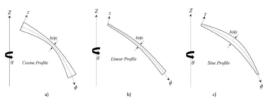
In the present work, cosine, linear and sine thickness profiles as shown in Figure 3 are utilized to state variable thickness in ϕ direction for EPRS. h(ϕ) is the thickness function of laminated composite EPRS. Thickness functions for cosine, linear and sine profiles can be expressed as follows
in which β is the thickness variation factor along ϕ direction. h0 and h1 as shown in Figure 2 are the value of thickness in the starting and ending of curvilinear coordinate system.
EPRS having variable thickness profiles in ϕ direction. a) Cosine Profile, b) Linear Profile and c) Sine Profile
3 GOVERNING EQUATIONS
An elliptic shells of revolution can be defined with a curvilinear coordinate system ϕθz as shown in Figure 2. Green-Lagrange nonlinear strain-displacement relations without any simplification for shells of revolution structures were derived using theory of surfaces in the recent article by Kalbaran and Kurtaran (2019Kalbaran, Ö., Kurtaran, H., (2019). Nonlinear Transient Dynamic Analysis of Laminated Composite Parabolic Panels of Revolution with Variable Thickness Resting on Elastic Foundation. Composite Structures 229:111402.). These relationships for EPRS can be represented as below
where Aϕ and Aθ are the Lame parameters for shells of revolution and they can be stated as follows
Detailed derivation of Green-Lagrange nonlinear strain-displacement relations are given in the recent article by Kalbaran and Kurtaran (2019Kalbaran, Ö., Kurtaran, H., (2019). Nonlinear Transient Dynamic Analysis of Laminated Composite Parabolic Panels of Revolution with Variable Thickness Resting on Elastic Foundation. Composite Structures 229:111402.). In this study, FSDT is used in EPRS formulations. Displacements field of the middle surface at a general point (ϕ, θ, z) considering FSDT are as follows
in which Ψθ and Ψϕ represent the rotations about ϕ and θ axes, respectively. , and are the middle surface displacements along the curvilinear coordinates ϕ, θ and z, respectively. Green-Lagrange nonlinear strains-displacement relations for EPRS from the point of middle surface rotations and displacements are given as below
Rearranging Equation (6) yields
in which the terms of strain displacement relationship in Equation (7) are represented in Appendix A. By keeping terms including z 2 and by expanding series as
Nonlinear strain displacement relations for shells of revolution in Equation (7) can be collected for membrane and transverse shear parts as below
The terms in Equation (9) can be written as follows
Strain-displacement relationships in Equation (9) can be also expressed in matrix form as below
where ε s and ε b state transverse shear and membrane strain vectors, respectively.
3.1 Constitutive Equations
The constitutive equation for a laminated composite EPRS can be obtained in terms of membrane force and moment resultants as
where
The constitutive equation for transverse shear can be written as below
where
express stiffness coefficients describing in-plane, bending-stretching coupling and bending stiffnesses. They can be written as
indicate transverse shear stiffnesses and they can be given as
in which (i=4,5) and state the shear correction factors and transformed stiffness coefficients of k-th layer, respectively.
3.2 Equilibrium Equation for EPRS
Equilibrium equation for composite EPRS with variable thickness resting on W-P elastic foundation is derived utilizing the virtual work principle, in this work. According to virtual work principle, virtual work of external force is equal to the summation of virtual works of elastic foundation and internal forces. The visual expression of elastic foundation between the ground and laminated composite EPRS is illustrated in Figure 2-a. where k w and k G express Winkler and Pasternak modulus, respectively. Virtual work principle for the laminated composite EPRS having variable thickness resting on W-P elastic foundation can be expressed as follow
where q z is distributed load as illustrated in Figure 2-a and it is applied on the mid-surface of EPRS. Equation (20) can be rearranged concerning force and moment resultants as below
4 TECHNIQUE FOR SOLVING EQUILIBRIUM EQUATION
Due to the irregular geometric shape of the EPRS, the geometric mapping theory is implemented to calculate integrals numerically in the equilibrium equation in Equation (21). As can be seen from Figure 4, elliptic shell area is discretized into grid points. In the current study, GDQ method is utilized to compute partial derivatives. The GDQ method replaces a given partial space derivative of a function by a linear weighted sum of the function values at the discrete grid points. Partial space derivatives of a function at an arbitrary grid point using GDQ technique can be expressed as
Where and indicate the total number of grid point in and directions. s-th and r-th are the orders of partial space derivative and in and directions. In this work, Gauss-Lobatto quadrature rule is employed in calculating spatial derivatives of field variables and numerical integrals. Gauss-Lobatto quadrature rule can locate grid points at boundaries which allow the application of the boundary conditions easily. Detailed derivations of the GDQ method and geometric mapping transformation for the shells of revolution structures are given in the recent article of (Kalbaran and Kurtaran (2019Kalbaran, Ö., Kurtaran, H., (2019). Nonlinear Transient Dynamic Analysis of Laminated Composite Parabolic Panels of Revolution with Variable Thickness Resting on Elastic Foundation. Composite Structures 229:111402.)).
After discretization process of EPRS domain, equilibrium equation as seen in Equation (21) can be expressed in matrix form as below
where F and P indicate external and internal vectors, respectively. Nonlinear static equilibrium equation in Equation (25) can be solved by using iterative Newton Raphson technique. In the implicit solution procedure, equilibrium equation in residual form is expressed where displacements can be calculated as follow
Residual equation is linearized leading to the incremental equilibrium equation as
where K and U matrix indicate tangent stiffness matrix and displacement values, respectively. Displacement increments are obtained by solving residual equation iteratively. Converged displacement values are obtained by adding displacement increments to the displacement values of previous iteration. The following convergence criteria is used in this study as below
where F norm and R norm denote norm of external and residual forces, respectively. Convergence tolerance is used as Conv≤0.005 in this study.
4.1 Boundary Conditions for EPRS
In this work, all edges simply-supported (SSSS) and all edges clamped (CCCC) boundary conditions of EPRS are considered. Boundary conditions apply to external grids (boundary grids).
Generic edge is fully clamped:
Generic edge is fully simply-supported:
5 CONVERGENCE AND VALIDATION STUDIES FOR EPRS
GDQ method is utilized to obtain nonlinear static behavior of laminated composite EPRS having variable thickness. For this purpose, a computer program for EPRS has been developed to solve the nonlinear equilibrium equations using GDQ method. Firstly, GDQ code is validated with linear static response of laminated composite spherical panel resting on Winkler elastic foundation which is available in the literature (Tornabene and Ceruti (2013Tornabene, F., Reddy, J., (2013). FGM and laminated doubly-curved and degenerate shells resting on nonlinear elastic foundations: a GDQ solution for static analysis with a posteriori stress and strain recovery. J. Indian Inst. Sci 93:635-688.)). Secondly, GDQ code is validated with nonlinear static behavior of laminated composite EPRS having variable thickness using commercial software ANSYS. SHELL281 shell element is used with ANSYS analyses. Results of mesh with 50x50 shell elements in xand y directions are used to present the results. The used mesh is sufficient to obtain the converged results. Central point of EPRS can be described by
In this study, displacement results are negative in tables and figures since uniformly distributed load is applied in negative z direction because of the selected coordinate system. Therefore absolute values should be considered in interpreting the magnitude of the results.
Linear static responses of a composite spherical panel resting on elastic foundation at panel center are investigated for validation under uniformly distributed load considering simply-supported boundary condition in Table 1. Geometric parameters of laminated composite spherical panel and applied load are taken as R ϕ = R θ =10 m, R b =0 m, ϕ∈[π/3, 2π/3], θ∈[-π/6, π/6], h=0.09 m, q z =-10 kPa (Tornabene and Ceruti (2013Tornabene, F., Reddy, J., (2013). FGM and laminated doubly-curved and degenerate shells resting on nonlinear elastic foundations: a GDQ solution for static analysis with a posteriori stress and strain recovery. J. Indian Inst. Sci 93:635-688.)). In this study, in all examples, material properties are specified as E 1=137.9 GPa, E 2=8.96 GPa, G 23=6.21 GPa, G 12=G 13=7.1 GPa, ρ=1450 kg/m3, ν 12=0.3 for laminated composite shells. As can be seen from the comparisons in Table 1, GDQ method results are in good agreement with the results of (Tornabene and Ceruti (2013)).
Linear static deflection of composite spherical panel resting on elastic foundation at panel center regarding SSSS boundary condition
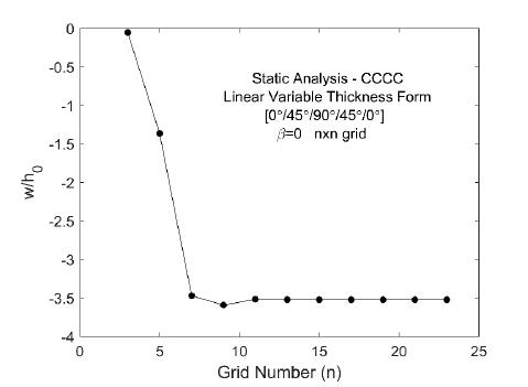
To specify the sufficient grid points to be used in Differential Quadrature method, a grid convergence case is carried out before beginning EPRS studies for static analysis. Nondimensional static analysis results at the center of laminated composite EPRS having uniform thickness for fully clamped boundary condition are illustrated in Figure 5. As can be seen from Figure 5, static responses start to converge for grid numbers n≥11. In this study, in all cases, 17×17 grids are used for GDQ method.
Grid convergence case studies for static analysis at the center of laminated composite EPRS regarding CCCC boundary condition
For validation, nonlinear static responses of laminated composite EPRS having linear variable thickness profile are investigated under uniformly distributed load for both boundary conditions. Geometric parameters of EPRS are taken as R b =0, a=4 m, b=4 m, h 0 =0.02 m, and range of ϕ and θ are given as [ϕ 0 , ϕ 1 ] = [0, 11π/24], [ϕ 1 , ϕ 2 ] = [11π/24, 13π/24], [θ 1 , θ 2 ] = [0, π/12]. Uniformly distributed load is q z =-2 MPa and the absolute values of the radii were used for ϕ>π/2.
Non-dimensional static responses of laminated composite EPRS having linear variable thickness profile for different value of thickness variation factor (β) a) CCCC boundary condition b) SSSS boundary condition
As can be seen from the Figure 6, non-linear static responses along the ϕ direction are in good agreement with the results obtained using ANSYS for different value of thickness variation factor and boundary conditions. FE solutions (50x50 quadrilateral shell elements elements) are achieved utilizing commercial software Ansys Parametric Design Language (APDL).
6 NUMERICAL RESULTS AND DISCUSSIONS
In this chapter, some results and discussions about the nonlinear static analysis of laminated composite EPRS under distributed load are presented in detail. Effects of thickness variation factor, thickness functions, W-P elastic foundation parameters, composite lamination scheme, characteristic parameter and boundary conditions on nonlinear static response are exemined in the solved examples. Geometric parameters of EPRS are taken as R b =0, b=4 m and h 0 =0.02 m in the examples. Uniformly distributed load is q z =-2 MPa.
6.1. Influence of characteristic parameter on static response
As a first step, the effect of the characteristic parameter on large displacement static response is investigated for clamped boundary condition. Three different characteristic parameter values (such as k=0.75, 1.00 and 1.25) of laminated composite EPRS having uniform and variable thickness profiles are considered. Range of ϕ and θ are given as [ϕ 0 , ϕ 1 ] = [0, 5π/12], [ϕ 1 , ϕ 2 ] = [5π/12, π/2], [θ 1 , θ 2 ] = [0, π/12]. Thickness variation factor (β) is given 0, 0.25 and 1. Cosine, linear and sine profiles as seen in Figure 3 are used for thickness variation. Stacking sequence of laminated composite layers is taken [0°/45°/90°/45°/0°].
Nonlinear static analysis results at the center of EPRS having uniform and variable thickness profiles considering clamped boundary condition are shown in Table 2. Displacement values of EPRS on static responses in Table 2 are observed to be minimum for all variable thickness profiles when the characteristic parameter is k=1.25. Maximum displacement values obtained in static analysis for EPRS occur when the characteristic parameter is k=1 considering β=0 and β=0.25. In Table 2, thickness variation factor is taken as β =0.25 and it is seen that for the case of k=0.75 and 1, the results are close to each other and much higher than those for the case of k=1.25.
Nonlinear static analysis results at the center of EPRS having uniform and variable thickness considering CCCC boundary condition.
6.2 Influence of thickness profile and stacking sequence on static response
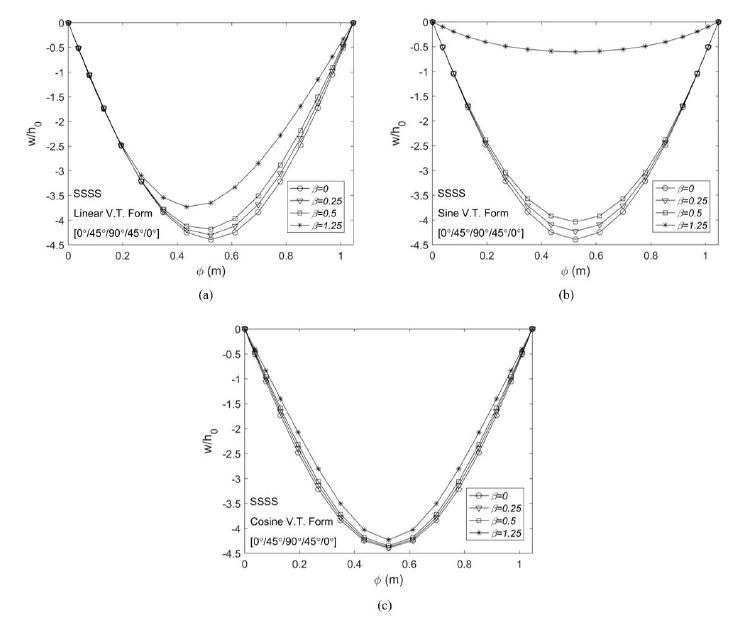
Here, the effect of the thickness variation factor and profile on large displacement static response is examined for clamped and simply-supported boundary conditions. Thickness profiles and stacking sequence of laminated composite layers used in this example are identical with the previous example. Range of ϕ and θ are given as [ϕ 0 , ϕ 1 ] = [0, 11π/24], [ϕ 1 , ϕ 2 ] = [11π/24, 13π/24], [θ 1 , θ 2 ] = [0, π/12]. Semi-major axis of the elliptic curve is considered a=4 m. To investigate the effect of thickness profile, β’s are considered as 0, 0.25, 0.5 and 1.25.
Figures 7 and 8 illustrate variation of displacement along ϕ direction for clamped and simply-supported boundary conditions at θ=π/24. Figures 7 and 8 demonstrate that as the thickness variation factor increases, displacement values decrease for all thickness profiles considering both boundary conditions. Also, thickness profile has more influential effect on the displacement results for clamped boundary condition compared to simply-supported boundary condition. As seen in Figures 7 and 8, sine and cosine thickness profiles yield symmetrical displacement forms unlike the linear profile. The β parameter does not an have important effect on displacements for simply-supported boundary condition except for the sine profile.
In Figures 9 and 10, static responses of EPRS with different thickness profiles are compared for β=0.25 and β=1.25. When the thickness variation factor is β=0.25 as seen in Figures 9-a and 10-a, the β parameter has a similar effect on displacement results for the considered thickness profiles and boundary conditions. Conversely, the static responses differ for the three different thickness profiles when the thickness variation factor is β=1.25. Displacement values of EPRS having sine variable thickness profile in Figures 9 and 10 on static responses are observed to be minimum for β=1.25. In addition, the largest displacement values occur in cosine form for β=1.25. As can be seen from Figures 7-10, the displacement values of the clamped boundary condition are always lower than the simply-supported boundary condition. As can be seen from the Figures 9 and 10, sine and cosine thickness profiles yield symmetrical displacement forms unlike the linear profile. Sine and cosine thickness profiles are symmetric but linear thickness profile is not symmetric in longitudinal direction (in ϕ direction). Therefore, the response is not symmetric for linear thickness profile.
Finally, the effect of the changing of composite angles on thickness profiles is examined in Figure 11. Stacking sequence of angle-ply laminated composite layers is taken [α°/ -α°/ α°/ -α°/ α°]. α are considered as 30°, 60° and 90°. Figure 11 shows nonlinear static response of EPRS having variable thickness for three different stacking sequence considering the clamped boundary condition. As shown in Figure 11, different static responses have been obtained for three thickness profiles when a different stacking sequence is used, for β=0.25. In addition, lowest displacement values occur when α is taken as 90° considering all variable thickness forms.
Non-dimensional static responses of clamped EPRS with variable thickness considering different thickness variation factors along ϕ direction a) Linear Profile, b) Sine Profile and c) Cosine Profile
Non-dimensional static responses of simply-supported EPRS with variable thickness considering different thickness variation factors along ϕ direction a) Linear Profile, b) Sine Profile and c) Cosine Profile
Non-dimensional static responses of clamped EPRS considering different thickness profiles along ϕ direction a) β=0.25, b)β=1.25
Non-dimensional static responses of simply-supported EPRS considering different thickness profiles along ϕ direction a) β=0.25, b) β=1.25
Non-dimensional static behavior of clamped angle-ply composite EPRS with variable thickness along ϕ direction a) Linear Profile, b) Sine Profile and c) Cosine Profile
6.3 Influence of W-P elastic foundation on static response
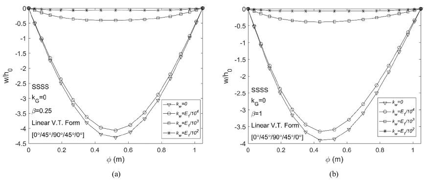
Finally, the effect of W-P elastic foundation on large displacement static response of laminated composite EPRS having linear variable thickness profile is examined along ϕ direction at θ=π/24. β is taken as 0.25 and 1. Geometric parameters and material properties used in this example are identical with the previous example (Section 6.2). Stacking sequence of laminated composite layers is taken [0°/45°/90°/45°/0°]. Winkler modulus of k w =0, k w =E 1/104, k w =E 1/103 and k w =E 1/102 and Pasternak shear modulus of k G= G 12/104, k G= G 12/103 and k G= G 12/102 are considered as elastic foundation parameters.
Figures 12 and 13 show non-dimensional static responses of EPRS having linear variable thickness resting on Winkler elastic foundation (k G = 0) for clamped and simply-supported boundary conditions. As can be seen from Figures 12 and 13, displacement values decrease with increasing values of Winkler elastic foundation parameter for β=0.25 and β=1. Increasing Winkler modulus generally has important effect on displacement results for considered boundary conditions. However, this effect is more prominent for Winkler modulus higher than E 1 /104.
Figures 14 and 15 demonstrate non-dimensional static responses of EPRS having linear variable thickness resting on W-P elastic foundation (k w = E 1 /104) for clamped and simply-supported boundary conditions. As seen in Figures 14 and 15, displacement values decrease with increasing values of Pasternak modulus for β=0.25 and β=1. Pasternak modulus higher than G 12 /104 has amplitude-reducing effect for both boundary conditions. Effect of Pasternak modulus on displacement is gradual considering clamped boundary condition.
Non-dimensional static responses of EPRS having linear variable thickness resting on Winkler elastic foundation considering CCCC boundary condition a) β=0.25, b) β=1
Non-dimensional static responses of EPRS having linear variable thickness resting on Winkler elastic foundation considering SSSS boundary condition a) β=0.25, b) β=1
Non-dimensional static responses of EPRS having linear variable thickness resting on W-P elastic foundation considering CCCC boundary condition a) β=0.25, b) β=1
Non-dimensional static responses of EPRS having linear variable thickness resting on W-P elastic foundation considering SSSS boundary condition a) β=0.25, b) β=1
7 CONCLUSIONS
This paper presents large displacement static analysis of laminated composite EPRS having variable thickness resting on W-P elastic foundation for CCCC and SSSS boundary conditions using GDQ technique. To determine the variable thickness, three types of thickness profiles namely cosine, sine and linear functions were used. Equilibrium equations were derived via virtual work principle using Green-Lagrange nonlinear strain-displacement relationships considering the deepness terms and spatial derivatives were calculated via GDQ method. Nonlinear static equilibrium equations were solved using Newton-Raphson method. Some results and discussions about the nonlinear static analysis of laminated composite EPRS under distributed load were presented in detail. Effects of thickness variation factor, thickness functions, W-P elastic foundation parameters, composite lamination scheme, characteristic parameter and boundary conditions on nonlinear static response were exemined in the solved examples
Results of this study can be summarized as follows:
-
Displacement values of EPRS on static responses are observed to be minimum for all thickness profiles when the characteristic parameter is k=1.25.
-
The effect of thickness variation factor on displacement results is similar for linear, cosine and sine thickness profiles when β is 0.25 and stacking sequences is [0°/45°/90°/45°/0°].
-
Static responses have been obtained for three different thickness profiles considering various stacking sequences (α=30, 60 and 90) for β=0.25.
-
Lowest displacement values occur when α is taken as 90° considering all variable thickness forms for β=0.25.
-
Displacement results of CCCC boundary condition are more effected by variation in thickness profiles compared to those of SSSS boundary condition.
-
Displacements decrease for all considered boundary conditions and thickness profiles, when the thickness variation factor (β) increases.
-
Sine and cosine thickness profiles yield symmetrical displacement profiles unlike the linear profile on static analysis.
-
Largest peak displacement values occur in cosine thickness profile.
-
As the β-value increases, differences in displacement values become more apparent.
-
Displacement values decrease with increasing values of Winkler and Pasternak modulus.
-
Pasternak modulus, which is higher than G 12 /104, have significant amplitude-reducing effect.
-
Winkler modulus, which is higher than E 1 /104, have significant amplitude-reducing effect.
References
- Al-Khatib, O.J., Buchanan, G.R., (2010). Free vibration of a paraboloidal shell of revolution including shear deformation and rotary inertia. Thin-walled structures 48:223-232.
- Amabili, M., (2008). Nonlinear vibrations and stability of shells and plates, Cambridge University Press.
- Arefi, M., (2014). A complete set of equations for piezo-magnetoelastic analysis of a functionally graded thick shell of revolution. Latin American Journal of Solids and Structures 11:2073-2092.
- Ataabadi, P.B., Khedmati, M.R., Ataabadi, M.B., (2014). Free vibration analysis of orthtropic thin cylindrical shells with variable thickness by using spline functions. Latin American Journal of Solids and Structures 11:2099-2121.
- Awrejcewicz, J., Kurpa, L., Shmatko, T., (2013). Large amplitude free vibration of orthotropic shallow shells of complex shapes with variable thickness. Latin American Journal of Solids and Structures 10:149-162.
- Bich, D.H., Van Dung, D., (2012). Nonlinear static and dynamic buckling analysis of functionally graded shallow spherical shells including temperature effects. Composite Structures 94:2952-2960.
- Bich, D.H., Van Dung, D., Nam, V.H., Phuong, N.T., (2013). Nonlinear static and dynamic buckling analysis of imperfect eccentrically stiffened functionally graded circular cylindrical thin shells under axial compression. International Journal of Mechanical Sciences 74:190-200.
- Civalek, O., Ulker, M., (2005). HDQ-FD integrated methodology for nonlinear static and dynamic response of doubly curved shallow shells. Structural Engineering and Mechanics 19:535-550.
- Duarte Filho, L.A., Awruch, A.M., (2004). Geometrically nonlinear static and dynamic analysis of shells and plates using the eight-node hexahedral element with one-point quadrature. Finite Elements in Analysis and Design 40:1297-1315.
- Isoldi, L.A., Awruch, A.M., Teixeira, P.R.d.F., Morsch, I.B., (2008). Geometrically nonlinear static and dynamic analysis of composite laminates shells with a triangular finite element. Journal of the Brazilian Society of Mechanical Sciences and Engineering 30:84-93.
- Jiammeepreecha, W., Chucheepsakul, S., (2017). Nonlinear static analysis of an underwater elastic semi-toroidal shell. Thin-Walled Structures 116:12-18.
- Jiashen, F., (2001). Static and dynamic stability for geometrically nonlinear governing equations of elastic thin shallow shells. Applied Mathematical Modelling 25:775-792.
- Kalbaran, Ö., Kurtaran, H., (2019). Nonlinear Transient Dynamic Analysis of Laminated Composite Parabolic Panels of Revolution with Variable Thickness Resting on Elastic Foundation. Composite Structures 229:111402.
- Kang, J.-H., (2007). Field equations, equations of motion, and energy functionals for thick shells of revolution with arbitrary curvature and variable thickness from a three-dimensional theory. Acta Mechanica 188:21-37.
- Li, Q., Chen, J., (2004). Nonlinear analysis of single-layer reticulated spherical shells under static and dynamic loads. Journal of Vibration and Control 10:731-754.
- Libai, A., Simmonds, J.G., (2005). The nonlinear theory of elastic shells, Cambridge university press.
- Meek, J., Wang, Y., (1998). Nonlinear static and dynamic analysis of shell structures with finite rotation. Computer Methods in Applied Mechanics and Engineering 162:301-315.
- Moita, J.S., Correia, V.F., Soares, C.M.M., Herskovits, J., (2019). Higher-order finite element models for the static linear and nonlinear behaviour of functionally graded material plate-shell structures. Composite Structures 212:465-475.
- Nath, Y., Dumir, P., Bhatiaf, R., (1985). Nonlinear static and dynamic analysis of circular plates and shallow spherical shells using the collocation method. International journal for numerical methods in engineering 21:565-578.
- Nejad, M.Z., Jabbari, M., Ghannad, M., (2017). A general disk form formulation for thermo-elastic analysis of functionally graded thick shells of revolution with arbitrary curvature and variable thickness. Acta Mechanica 228:215-231.
- Paliwal, D., Srivastava, R., (1993). Nonlinear static behaviour of shallow spherical shell on a Kerr foundation. International journal of pressure vessels and piping 55:481-494.
- Polat, C., Calayir, Y., (2010). Nonlinear static and dynamic analysis of shells of revolution. Mechanics Research Communications 37:205-209.
- Qatu, M.S., (2004). Vibration of laminated shells and plates, Elsevier.
- Reddy, J.N., (2004). Mechanics of laminated composite plates and shells: theory and analysis, CRC press.
- Saada, A.S., (2013). Elasticity: theory and applications, Elsevier.
- Shariyat, M., Alipour, M., (2017). Analytical bending and stress analysis of variable thickness FGM auxetic conical/cylindrical shells with general tractions. Latin American Journal of Solids and Structures 14:805-843.
- Shaterzadeh, A., Foroutan, K., Ahmadi, H., (2019). Nonlinear Static and Dynamic Thermal Buckling Analysis of Spiral Stiffened Functionally Graded Cylindrical Shells with Elastic Foundation. International Journal of Applied Mechanics 11: 1950005.
- Tornabene, F., (2011a). 2-D GDQ solution for free vibrations of anisotropic doubly-curved shells and panels of revolution. Composite Structures 93:1854-1876.
- Tornabene, F., (2011b). Free vibrations of anisotropic doubly-curved shells and panels of revolution with a free-form meridian resting on Winkler-Pasternak elastic foundations. Composite Structures 94:186-206.
- Tornabene, F., Ceruti, A., (2013). Free-Form Laminated Doubly-Curved Shells and Panels of Revolution Resting on Winkler-Pasternak Elastic Foundations: A 2D GDQ Solution for Static and Free Vibration Analysis. World J. Mech 3:1-25.
- Tornabene, F., Fantuzzi, N., (2014). Mechanics of laminated Composite doubly-curvel shell structures: The generalized differential quadrature method and the strong formulation finite element method, Società Editrice Esculapio.
- Tornabene, F., Fantuzzi, N., Bacciocchi, M., (2016). The local GDQ method for the natural frequencies of doubly-curved shells with variable thickness: a general formulation. Composites Part B: Engineering 92:265-289.
- Tornabene, F., Fantuzzi, N., Bacciocchi, M., (2017a). Linear static behavior of damaged laminated composite plates and shells. Materials 10:811.
- Tornabene, F., Fantuzzi, N., Bacciocchi, M., Reddy, J., (2017b). A posteriori stress and strain recovery procedure for the static analysis of laminated shells resting on nonlinear elastic foundation. Composites Part B: Engineering 126:162-191.
- Tornabene, F., Liverani, A., Caligiana, G., (2012). General anisotropic doubly-curved shell theory: a differential quadrature solution for free vibrations of shells and panels of revolution with a free-form meridian. Journal of Sound and Vibration 331:4848-4869.
- Tornabene, F., Reddy, J., (2013). FGM and laminated doubly-curved and degenerate shells resting on nonlinear elastic foundations: a GDQ solution for static analysis with a posteriori stress and strain recovery. J. Indian Inst. Sci 93:635-688.
- Viebahn, N., Pimenta, P.M., Schröder, J., (2017). A simple triangular finite element for nonlinear thin shells: statics, dynamics and anisotropy. Computational Mechanics 59:281-297.
- Viola, E., Tornabene, F., Fantuzzi, N., (2013). Static analysis of completely doubly-curved laminated shells and panels using general higher-order shear deformation theories. Composite Structures 101:59-93.
- Wang, Q., Cui, X., Qin, B., Liang, Q., Tang, J., (2017a). A semi-analytical method for vibration analysis of functionally graded (FG) sandwich doubly-curved panels and shells of revolution. International Journal of Mechanical Sciences 134:479-499.
- Wang, Q., Qin, B., Shi, D., Liang, Q., (2017b). A semi-analytical method for vibration analysis of functionally graded carbon nanotube reinforced composite doubly-curved panels and shells of revolution. Composite Structures 174:87-109.
- Wang, Q., Shi, D., Liang, Q., Pang, F., (2017c). Free vibrations of composite laminated doubly-curved shells and panels of revolution with general elastic restraints. Applied Mathematical Modelling 46:227-262.
- Wei-ping, Z., Qian, H., (2002a). Finite element displacement perturbation method for geometric nonlinear behaviors of shells of revolution overall beding in a meridional plane and application to bellow (II). Applied Mathematics and Mechanics 23:1390-1406.
- Wei-ping, Z., Qian, H., (2002b). Finite element displacement perturbation method for geometric nonlinear behaviors of shells of revolution overall bending in a meridional plane and application to bellows (I). Applied Mathematics and Mechanics 23:1374-1389.
- Zhang, D.-G., (2015). Nonlinear static analysis of FGM infinite cylindrical shallow shells based on physical neutral surface and high order shear deformation theory. Applied Mathematical Modelling 39:1587-1596.
Appendix A
Terms of nonlinear strain displacement relationship in Equation (7) are given in Appendix A to save space.
Edited by
Editor:
Publication Dates
-
Publication in this collection
20 Dec 2019 -
Date of issue
2019
History
-
Received
23 Oct 2019 -
Reviewed
29 Oct 2019 -
Accepted
30 Oct 2019 -
Published
05 Nov 2019