Abstract
Because soluble salt in saline soil dissolves with water, utility tunnels built in saline soil foundation are more likely to damage due to by groundwater and earthquake. In this study, new cementitious composite materials were developed by using slag, building gypsum, quicklime, and magnesia. The unconfined compressive strengths of the saline soil solidified by new cementitious composite materials and cement are investigated, and the optimum proportion of the different components of the new cementitious composite materials is determined. We found from microscopic characteristics of the saline soil solidified by the new cementitious composite materials and cement that the new materials could better absorb chloride ions. Finally, the new cementitious composite materials were applied to saline soil foundation reinforcement of a utility tunnel. By using the finite element method (FEM) and shaking table tests, it can be seen that the displacement, acceleration and extent of damage of the utility tunnel after saline soil foundation reinforcement using new cementitious composite materials significantly decreased; therefore, the new cementitious composite materials can improve the seismic behaviour of the utility tunnel and shows potential future engineering application value.
Keywords:
new cementitious composite materials; unconfined compressive strength; saline soil; utility tunnel; seismic behaviour
1. Introduction
As a special rock and soil mass, saline soil shows a high structural strength in its natural state due to cementation caused by the salt. After saline soil is immersed in water, soluble salt is dissolved so that the soil structure is damaged, thus greatly decreasing the bearing capacity and compression modulus of saline soil. For this reason, the engineering properties of the saline soil are complicated (Wen, 2012Wen T. (2012). Study of engineering properties and improvement of loessial sulfate saline soil in the northwest area[D]. Lanzhou: Lanzhou University of Technology.). If the engineering structures are built in saline soil foundation, the seriously uneven settlement of the foundation, affected by groundwater and earthquake, causes utility tunnel wall to crack. Therefore, the purpose of the study is to develop cementitious new composite materials to solidify saline soil foundation, thus improving the seismic behaviour of the utility tunnel built in saline soil foundation.
At present, the methods for solidifying saline soil involve dynamic compaction, soil removal and replacement, lowering groundwater level, salinization, and solidified grouting (Yang et al. 2014Yang X. F, You Z. M, Niu F. J. et al. (2014). Research progress in stabilizers and their effects in improving physical and mechanical properties of saline soil [J]. Journal of Glaciology and Geocryology 36(2): 376 -385.; Li, Chai, 2018Li H. B., Tian J. C., Nan H. B., Xu D. B., Gu H. T. (2018). Efficacy of four consolidation agents in improving mechanical properties of salinized foundation soil of channels[J]. Journal of Irrigation and Drainage 37(12):93-99.). About researching on the saline soil foundation reinforcement, Li and Li (2015) used grouting reinforcement method treat with the subsidence of existed buildings in saline soil area. Zhang et al. (2011Zhang Y, Fang J. H., Liu J. K., Xu A. H. (2011). Field tests on reinforcement effects of ground treatment of composite foundation in saline soils by dynamic compaction replacement[J]. Chinese Journal of Geotechnical Engineering 33(1):251-254.) studied the reinforcement effects of the composite foundation in saline soils by dynamic compaction replacement, and found that the dynamic compaction replacement has good reinforcement effects for saline soils. Wu et al. (2018Wu P.P., Chen W.Z., Ding Z.F. (2018). Key technology of soft saline soil foundation reinforcement of saline lake in high intensity area[J]. High Speed Railway Technology 9(2):37-42.) compared reinforcement proposals of soft saline soil foundation, and determined the key technologies. Ren and Wei (2016Ren Z. G., Wei Y. (2016). Experimental Study on New Reinforced Material for Foundation of Salty Soil [J]. Resources Environment & Engineering 30(3):410-414.). determined the best ratio of curing agent to solidify the saline soil. Li et al. (2018) suggested that amending the saline soil with cement and fly ash at high ratio can achieve good effect. Yin et al. (2013Yin B. C., Gu Q. K, Xu S. Z0, Li Q., Qu B. (2013). The test study of salty soil foundation treatment with chemical modified method[J]. Construction Technology 42(13):52-55.) studied the effect of CaCl2 to inhibit the secondary salinization of sulphate salty soil ground. Zhang et al. (2018) studied the collapsibility characteristics and influencing factors of saline soil foundation, and found that the size effect of skeleton particles has a significant influence on the bearing capacity and collapsibility coefficient of the foundation. Researches showed that saline soil stabilised by solidifying materials showed lots of advantages such as resource conservation, low cost, and environmental protection (Qi, Liu, 2015Qi F. C., Liu W. J. (2015). Subgrade Design and Construction Technology in Saline Soil Area[J]. Railway Construction Technology 8: 69-72.; Zhang et al. 2019; Yin et al. 2013). From the perspective of effectively utilising resources, saving resources, and protecting the environment, the application of slag in industrial cementitious materials is of interest in many countries around the world (Cheng et al. 2016Cheng Y., Yu H., Zhu B. L., Wei D. X. (2016). Laboratory investigation of the strength development of alkali-activated slag-stabilized chloride saline soil[J]. Journal of Zhejiang University-Science A 17(5):389-398.; Qi, Liu, 2015). Slag has potential activity which is latent unless activated under certain conditions, and the main activation modes include mechanical activation, chemical activation, and high-temperature activation. Based on practical engineering experience, chemical activation was used in this study.
About researching on chemical activation, Jin and Wang (2005Jin Z. P, Wang P. M. (2005). A laboratorial study of system“slag-light burnt magnesia-alkali”as cementitious material[J]. Housing Materials & Applications 33(183):1-3.) made a new inorganic composite cementitious material by using blast furnace slag, light-burned MgO, alkali-water glass, potassium hydroxide, and found that the material shows favourable mechanical properties. Lou et al. (1998Lou Z. H., Ye Q., Chen H. X., Wang Y. Q., Shen J. L. (1998). Hydration of mgo in clinker and its expansion property[J]. Journal Of The Chinese Ceramic Society 4:430-436.) made double-expansive cements by adding MgO into low-heat micro-expansive cements, and the cements realising shrinkage-compensation are mainly by the synchronous expansion of aluminite and MgO; in addition, a suitable expansion rate and expansive distribution can compensate for the drawback of volumetric shrinkage of the cements after being hardened. Harrison (2003Harrison J. (2003). New Cements Based on the Addition of Reactive Magnesia to Portland Cement with or without added Pozzolan[C]. Proc.CIA Conference: Concrete in the Third Millenium, CIA. Brisbane, Australia:24-35.) developed a new cementitious material called active MgO cement by adding a certain amount of active MgO to Portland cement, together with about 80% fly ash. Liska et al. (2007Liska M., Vandeperre L. J., Al-Tabbaa A. (2007). Influence of carbonation on the properties of reactive magnesia cement-based pressed masonry units [J].Advanced in Cement Research 19(1):1-12.) developed a new cementitious material, which realises shrinkage-compensation through hydration of active MgO to magnesium hydroxide, by blending active MgO, volcanic ash, and hydraulic cement. Inspired by the previous studies, a new composite cementitious material was developed by using mineral powder, magnesia, quicklime, and gypsum; quicklime and gypsum are as activators. Finally, the new cementitious composite materials were applied to reinforce saline soil foundation of a utility tunnel to investigate the seismic behaviour of the utility tunnel before and after foundation reinforcement, and this work could provide important technological guidance for seismic design of the utility tunnel.
2. New cementitious composite materials
2.1 Component analysis
By analysing main chemical compositions of the blast furnace slag, the chemical compositions contents are shown in Table 1.
As shown in Table 1, the highest content of blast furnace slag is CaO, and the content of the CaO is 38%, followed by SiO2 and Al2O3.
The new cementitious composite material was made by using slag, building gypsum, quicklime, and magnesia, and the key properties of the mineral powders are listed in Table 2.
As shown in Table 2, we could determine the activity ratio of the mineral powders, which is 0.769, and the content of SO3 is higher than the content of Cl-.
The Portland slag cements used in this study were purchased from Tangshan Jidong Cement Co., Ltd, Hebei Province, China, and their main performance indices are listed in Table 3.
As shown in Table 3, the initial set is 150 min, and the final set is 240 min. The water requirement of normal consistency of the cement, used in our study, is 28.1%, which shows that the cement has a good performance.
The saline soil from north-western China was used and its key components of soluble salt were analysed, as shown in Table 4.
It can be seen in Table 4, Cl-/SO4 > 2. Therefore, the saline soil was classified as a chlorine saline soil. When the average salinity in soil was in the range of 1 to 5, saline soil was subordinated to an intermediate saline soil. According to the above analysis of soluble salt contents, the average salinity of the test soil was 1.39; thus the saline soil in our study was classified as intermediate saline soil.
2.2 Determination of optimal proportions
Owing to saline soil containing a high water content (30%) and there being no cement clinker used in the test, the activity of MgO and micro-expansive properties of Mg (OH)2 were fully employed. The proportions of MgO in the cementitious composite material were successively set to: 4%, 5%, 6%, 7%, 8%, 9%, 10%, 11%, and 12%, respectively. By comparing strengths of the saline soil solidified by cementitious composite materials with different proportions of MgO, the optimal dose of MgO in the cementitious composite material was determined. The test blocks of the saline soil solidified by cementitious composite materials were cured for 7, 14, 28, 56, 90, 180, and 360d, respectively. The proportions of the solidifying materials are listed in Table 5.
In order to determine the optimal proportion of different components in the new cementitious composite materials, the influence of the different proportions of solidifying material on the unconfined compressive strength (UCS) of solidified saline soil was investigated, as shown in Table 5. Additionally, the amounts of the cementitious composite materials added in this solidified saline soil were separately set to 7%, 10%, 15%, and 20%, as shown in Figure 1.
It can be seen from Figure 1, the UCS of the solidified saline soil all initially increased and then decreased at different curing ages with the increasing proportion of MgO. As the added amount of MgO was increased from 4% to 10%, the UCS of the solidified saline soil increased; as the added amount of MgO was increased from 10% to 12%, the UCS of the solidified saline soil decreased. Moreover, the growth in strength of solidified saline soil caused by increasing addition of MgO (from 4% to 10%) was more significant than the reduction of strength induced by decreasing addition of mineral powder. That is, the improvement of active and micro-expansive effects of MgO mainly attributed to the growing addition amount of MgO. As the added amount of MgO was increased from 10% to 12%, the active effect of MgO increased while the active effect of mineral powders decreased. In this case, the large micro-expansive effect of MgO caused the reduction of the solidified saline soil strength. With the increasing of the solidifying materials, the strength of solidified saline soil increased significantly. The optimal proportions of the new cementitious composite materials were: 75% mineral powders, 7.5% calcium oxide, 7.5% gypsum, and 10% active MgO.
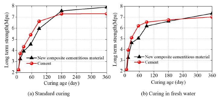
The use of the long-term UCS can save the engineering cost; thus, we investigated the UCS of the specimens at the curing ages 7, 14, 28, 56, 90, 180, and 360d, and the specimens are cured through standard curing and immersion curing. The added amount of MgO in the cementitious composite materials was 10%, and the dosage of the new cementitious composite materials was 15%. The long-term UCS of the saline soil solidified by using the new cementitious composite materials and cement were shown in Figure 2.
Long-term strengths of saline soil solidified by using the new cementitious composite materials and cement
It can be seen from Figure 2, with the increasing of the curing age from 7d to 180d, the growth rate of the strength of saline soil solidified by cements was greater than that solidified by the new cementitious composite material. When the curing age is 180d, the UCS of the saline soil solidified by the new cementitious composite material began to be greater than that solidified by the cement through standard curing. When the curing age is 240d, the UCS of the saline soil solidified by the new cementitious composite materials began to be greater than that solidified by the cement through immersion curing. Moreover, the test blocks of saline soil solidified by the new cementitious composite material were undamaged after being immersed in water. This indicated that the generated hydration products had coated the soil particles so that internal structure was compact, which allowed the solidified saline soil to resist damage. Therefore, with the increasing of the curing ages, the strength of the saline soil solidified using two solidifying materials increase. However, when reaching a certain curing age, the strength of the saline soil solidified by the cement increased very slowly, and the strength of the saline soil solidified by the new cementitious composite materials also increased fast. The long-term strength of saline soil solidified using the new cementitious composite material was greater than that of saline soil solidified using cement.
2.3 SEM analysis
The microstructures of the saline soil solidified by using the cement and the new cementitious composite material (added amount, 15%) after standard curing 28d and 360d were investigated, as shown in Figure 3 and Figure 4.
SEM analysis on saline soil solidified using the two solidifying materials after standard curing 28d
SEM analysis on saline soil solidified by using cement and the cementitious composite material after standard curing 360d
As shown in Figure 3 and Figure 4, the internal structure of saline soil solidified by applying the new cementitious composite material for 28d was compact: soil particles, the microstructure of the saline soil, were uniformly distributed and they were surrounded by the cementitious material which is our developed new cementitious composite materials. Although the water content in test blocks reached 30%, the internal structure of the test blocks did not show significant defects, i.e. gaps, holes, and fractures. As a result, there was low possibility for the relative motion under the effect of external force, thus effectively improving the strength and stiffness of the solidified soil. By contrast, the internal structure of saline soil solidified by the cements for 28d was loose: significant gaps and holes were found between cementing agents and soil particles. After standard curing 360d, the saline soils solidified by using the two types of solidifying materials were both compact: soil particles were surrounded by hydration products and there were many clustered and petal-shaped C-S-H gels as well as flaky hydration products present. The main reason for this was that ettringite, Aft, and AFm were interactively crossed so that soil particles were less likely to relative motion, which was also the reason why the strength of the saline soil increased with prolonged curing time.
3.Reinforcement of the utility tunnel foundation
3.1 Physical Model
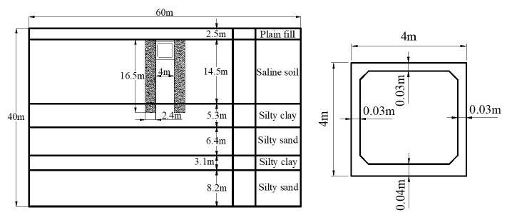
Utility tunnel is location in Tianjin city in China, whose earthquake fortification intensity is 7 degrees belongs to B-class. The utility tunnel was a single compartment, whose cross section is shown in Figure 5. The soil deposits were determined by hole drilling, and the soil deposits consisted of six layers. The underground water level was located at the ground surface.
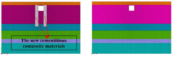
The seismic behaviour of the utility tunnel in saturated soil deposits was investigated using the finite element program MIDAS. Plane strain condition was assumed in the analysis. The dimensions of the domain were taken as 60m×40m. The rectangular tunnel had the dimensions of 4m×4m, the thickness of side wall and roof was 0.3m, and the thickness of the floor was 0.4m. The embedment depth of the utility tunnel was 3m below ground surface, as shown in Figure 5. The soil deposits and the underground structure were both modelled using quadrilateral isoparametric elements with four nodes. The interfaces between the soils and structure were modelled with thin layer element. The two-dimensional finite element models (2-D FE model) before and after reinforcement were presented in the Figure 6. An elastoplastic constitutive model based on Drucker-Prager yield criterion was used in the soil elements. The utility tunnel was modelled using linear elastic model, whose parameters were taken as the typical elastic properties of C30 concrete. The free field boundary conditions which could simulate the infinite domain and be highly effective for the absorption of the reflection wave at the artificial boundaries were used at both side boundaries. The soil and structure were all modelled Rayleigh damping in the material model. The earthquake loading was applied as a time-varying input acceleration acting horizontally on the bottom.
2-D FE model for utility tunnels before and after reinforcement by the new cementitious composite materials
3.2 Material Properties
The soil deposits were obtained through the borehole in the site which was 40-meter depth and consisted of six layers. The dynamic shear modulus ratio and damping ratio of silty clay obtained by means of dynamic hollow cylinder apparatus is the most advanced and complicated device in lab-testing on soil dynamics were presented in Figure 7. The groundwater level was located at the ground surface.
In numerical analysis, parameters of soil for calculation were obtained by in-situ and laboratory tests, i.e., dynamic triaxial test and the parameters were presented in Table 6.
3.3 Input Earthquake Motion
The basic intensity of the region of the utility tunnel is 7 degrees, and the site is II. According to CODE FOR SEISMIC DESIGN OF RAILWAY ENGINEERING (GB50111-2006) (Ministry of Railways of the People's Republic of China, 2006) of China, the basic acceleration value of severe earthquake is 0.38g, as shown in Table 7, and the peak accelerations of the seismic waves are adjusted for 0.38g.
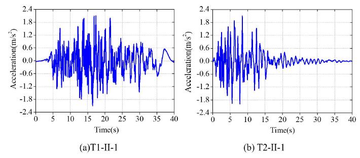
Refer to Japanese Specification for Highway Bridges (Japan Road Association, 2002), the far field seismic waves (Type I: T1-II-1) and the near field seismic waves (Type II: T2-II-1) were used, as shown in Table 8. The acceleration time-histories of the two seismic waves were shown in Figure 8. The earthquake motions were used as the horizontal excitations and input from the fixed bottom boundary.
Fourier Transform was conducted to obtain the response spectra of different seismic waves, as shown in Figure 9.
As shown in Figure 9, we obtained the seismic response spectrums of the acceleration time-histories by Fourier transform. The spectral values corresponding to far-field seismic wave (Type I) were distributed in period 0.25~1.5s in a centralized way. The distribution of the periodic domain was wide, and the acceleration response declined slowly with the increasing of the natural vibration period. For near-field seismic wave (Type II), the platform of the period of the acceleration response spectrum was short, and the corresponding spectral values were mainly distributed in period of 0~0.8s in a centralized way. With the increasing of the structural natural period of vibration, response acceleration reduced faster than plate boundary seismic waves.
4.Dynamic response of the utility tunnel
In the analysis of seismic response, we are more interested in maximum node displacement, dynamic amplification factor and structural internal forces (bending moment, shearing force and axial force), so we selected the roof and right side wall (the left and right side walls are symmetric) of the utility tunnel structure for comparative analysis. The monitoring points of the utility tunnel are shown in Figure 10.
4.1 Displacement response
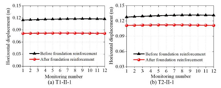
In order to more intuitively express the influence of foundation reinforcement using our newly-developed composite cementitious material on the seismic response of the utility tunnel, Figure 11 and Figure 12 present the maximum horizontal displacement of the utility tunnel under near and far field earthquakes.
As shown in Figure 11 and Figure 12, the horizontal displacement of the roof and the side wall decrease significantly after foundation reinforcement of the utility tunnel under near and far field earthquakes. The maximum horizontal displacement of the utility tunnel decreases 63% at most compared to no reinforcement under far field earthquake T1-II-1, while decreasing 71% under near field earthquake T2-II-1. Besides, the near-field earthquake T2-II-1 has greater influence on the horizontal displacement of the utility tunnel than that under far-field earthquake T1-II-1, and the maximum horizontal displacement under near-field earthquake T2-II-1 is 8% greater than the maximum horizontal displacement under far-field earthquake T1-II-1. Consequently, our developed new composite cementitious material has good reinforcement effect on the utility tunnel deformation.
4.2 Acceleration response
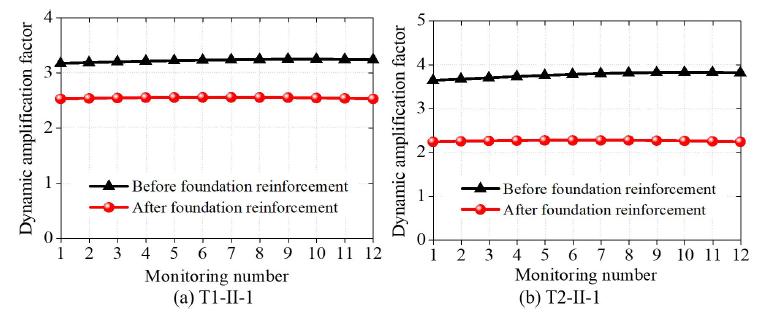
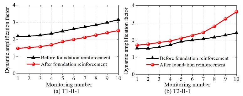
The dynamic amplification factors of the maximum horizontal acceleration of the utility tunnel are as shown in Figure 13 and Figure 14.
As shown in Figure 13 and Figure 14, we can see that the dynamic amplification factors of the roof and side wall after foundation reinforcement are less than that before reinforcement, which shows that the foundation reinforcement can play a role in passive energy dissipation on the utility tunnel. The maximum dynamic amplification factor of the utility tunnel decreases 14% at most compared to no reinforcement under far field earthquake T1-II-1, while decreasing 52% under near field earthquake T2-II-1. Near-field earthquake action has greater influence on the dynamic amplification factor of the utility tunnel than far-field earthquake action. The maximum dynamic amplification factor under near-field earthquake T2-II-1 is 19% greater than the maximum dynamic amplification factor under far-field earthquake T1-II-1. The utility tunnel structure is most vulnerable to damage under near-field earthquake T2-II-1, so more attention should be paid during engineering construction. Our developed new composite cementitious material not only has good reinforcement effect on the utility tunnel deformation, but also has good reinforcement effect in passive energy dissipation control.
4.3 Internal force analysis
In order to determine the change laws of internal forces of the utility tunnel structure before and after foundation reinforcement under near and far-field earthquakes, the distribution laws of internal forces of the utility tunnel structure were calculated, as shown in Table 9.
The maximum internal forces of the utility tunnel structure before and after foundation reinforcement
As shown in Table 9, the shearing force, bending moment and axial force of the utility tunnel before and after foundation reinforcement were obviously greater than those under far-field earthquake. Before foundation reinforcement, the maximum shearing force of the utility tunnel under near-field earthquake T2-II-1 was about 21% greater than that under far-field earthquake T1-II-1, the maximum bending moment of the utility tunnel under near-field earthquake T2-II-1 was about 20% greater than that under far-field earthquake T1-II-1, and the maximum axial force of the utility tunnel under near-field earthquake T2-II-1 is about 23% greater than that under far-field earthquake T1-II-1. After foundation reinforcement, the maximum shearing force of the utility tunnel under near-field earthquake T2-II-1 was about 15% greater than that under far-field earthquake T1-II-1, the maximum bending moment of the utility tunnel was about 23% greater than that under far-field earthquake T1-II-1, and the maximum axial force of the utility tunnel was about 23% greater than that under far-field earthquake T1-II-1. Under far-field earthquake T1-II-1, the maximum shearing force of the utility tunnel after foundation reinforcement decreased by 40%, the maximum bending moment decreased by 37%, and the maximum axial force decreased by 52% compared with no foundation reinforcement. Under near-field earthquake T2-II-1, the maximum shearing force of the utility tunnel after foundation reinforcement decreased by 44%, the maximum bending moment decreased by 36%, and the maximum axial force decreased by 51% compared with no foundation reinforcement. Consequently, it can be seen that the utility tunnel was more vulnerable to damage under near-field earthquake T2-II-1. The internal forces of the utility tunnel before foundation reinforcement were much greater than the internal forces of the utility tunnel after foundation reinforcement, which should be paid more attention during engineering protection.
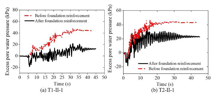
In addition, the main influencing factors of soil failure were the sharp increasing of the excess pore water pressure and the decreasing of effective stress. Consequently, the excess pore water pressure of the monitoring point A (Figure 13) before and after foundation reinforcement was conducted, as shown in Figure 15.
As shown in Figure 15, we can found that the excess pore water pressure increases with the continuing effects of earthquakes. The excess pore water pressure of the not reinforcement foundation were greater than that of the reinforcement foundation. The maximum excess pore water pressure of the not reinforcement foundation was 43KPa while the maximum excess pore water pressure of the reinforcement foundation was 18KPa under far field earthquake T1-II-1. The maximum excess pore water pressure of the not reinforcement foundation was 48KPa while the maximum excess pore water pressure of the reinforcement foundation was 30KPa under near field earthquake T1-II-1. Consequently, the excess pore water pressure of the soil decreased obviously after foundation reinforcement. Also, the excess pore water pressure caused by near field earthquake is greater than that caused by far field earthquake.
5.Shaking table test
From the above section, we may know near-field seismic action has the most influence on the dynamic response of the utility tunnel, and the internal forces of the utility tunnel were the greatest. For this reason, we did a shaking table test of progressive failure of the utility tunnel under near-field earthquake (T2-II-1), thus, we could determine the failure mode and failure position of the utility tunnel before and after foundation reinforcement using our newly-developed composite cementitious material.
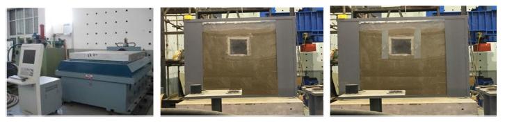
Figure 16 showed the shaking table test equipment to model the slope failure process under the seismic excitation.
As can be seen in Figure 16, the main technical indicators of the shaking table test equipment include rated working frequency (40Hz), the maximum acceleration (20m/s2), the maximum test load (5000kg) and dimensions of the shaking table (1.5m×1.5m).
The dimension of the model is determined according to the dimension of the shaking table. The dimension of the shaking table is 1.5m×1.5m, and the dimension of the model box is 0.5m (wide) ×2m (length) ×1.5m (height), and the test model is shown in Figure 17. The geometric similarity coefficient (Wei, Hu, 2019Wei, D., Hu, C. (2019). Scaling of an impacted reticulated dome using partial similitude method[J]. Latin American Journal of Solids and Structures, 16(2).) is set as 1:50, and other specific similarity coefficients are shown in Table 4. 20mm thick sponge was laid on the inner wall of the model box to reduce reflection of seismic waves on the boundary. Before the test, white noise was adopted for shock excitation on the top of the shaking table to tamp the soil.
The scaling law between our test model and the actual projects follow the Buckingham Pi theorem (Louis 1957Louis B. (1957). The Pi theorem of dimensional analysis[J]. Archive for Rational Mechanics and Analysis 1(1):35-45.). Owing to the complexity and particularity of soil, it is difficult to make soil and structure conform to the consistent similarity relations in model test. During the design of the test, only some non-critical similarity ratios were allowed to have distortion to assure the studied key issues conform to the similarity relations. The research of the shaking table test of the utility tunnel structure focused on dynamic response and failure mechanism of the utility tunnel structure, so utility tunnel structure’s compliance with the requirement of similarity ratio was mainly considered. The following different basic physical variables were selected: length, elasticity modulus and acceleration for model structure; shear wave velocity, density and acceleration for model soil. According to Bockingham π theorem, the similarity ratio S relations of the physical variables were derived, as shown in Table 10.
Next, we can more directly determine the failure mode and failure position of the utility tunnel before and after foundation reinforcement using our newly-developed composite cementitious material through shaking table test, as shown in Figure 18.
As can be seen in Figure 18, through shaking table test, we can more directly determine the failure mode and failure position of the utility tunnel before and after solidification. Before reinforcement, cracks first appeared at the junctions between the roof and side walls under earthquake T2-II-1. With the continuous action of the earthquake, cracks appeared on the middle of the roof and gradually the roof began to sink; Then the cracks spread and eventually the roof collapsed and the utility tunnel was fully destroyed under the joint effect of the seismic action and the gravity of the roof. After reinforcement, the initial cracks appeared at the junctions between the roof and side walls of the utility tunnel. With the continuous action of the earthquake, cracks spread, and bending failure at the crossing locations between roof and side walls first appeared, forming plastic hinges. In the end, the roof collapsed and the utility tunnel was completely failed under the combined effect of earthquake and roof gravity.
6.Conclusions
-
(1) New cementitious composite materials were developed by using slag, building gypsum, quicklime, and magnesia, and the optimal proportion of different components in the new cementitious composite materials were determined. The new cementitious composite materials could be better absorption of the chloride ions.
-
(2) The new cementitious composite materials were applied to saline soil foundation reinforcement, and the results show that the developed new composite cementitious material has better aseismic behaviour, and it significantly reduced the seismic dynamic response (displacement, acceleration, bending moment, shearing force, and axial force) of the utility tunnel.
-
(3) The failure mode and failure position of the utility tunnel are different before and after its foundation reinforcement. The damage extent of the utility tunnel was reduced significantly after its foundation reinforcement, and failure position is the position allowed by the structural design under earthquake.
Acknowledgments
This work is financially supported by the research grant from Institute of Crustal Dynamics, China Earthquake Administration (No. ZDJ2019-10), National Natural Science Foundation of China (Grant No.51708516), the Young Elite Scientists Sponsorship Program by CAST (2018QNRC001), Beijing Municipal Natural Science Foundation (8174078), National Key R&D Program of China (2017YFC1500404), and the research grant from Institute of Crustal Dynamics, China Earthquake Administration (No.ZDJ2017-14).
References
- Cheng Y., Yu H., Zhu B. L., Wei D. X. (2016). Laboratory investigation of the strength development of alkali-activated slag-stabilized chloride saline soil[J]. Journal of Zhejiang University-Science A 17(5):389-398.
- Harrison J. (2003). New Cements Based on the Addition of Reactive Magnesia to Portland Cement with or without added Pozzolan[C]. Proc.CIA Conference: Concrete in the Third Millenium, CIA. Brisbane, Australia:24-35.
- Jin Z. P, Wang P. M. (2005). A laboratorial study of system“slag-light burnt magnesia-alkali”as cementitious material[J]. Housing Materials & Applications 33(183):1-3.
- Japan Road Association. (2002). Specifications for Highway Bridges·Part V: Seismic Design 1st Ed[S]. Japan.
- Li W., Chai S. X. (2018). Evaluation of solidifying effect of SH agent on inshore saline soils[J]. Journal of Engineering Geology 26(2):407-415.
- Li J. L., Li Z. L. (2015). Treatment of backfill subsidence of buildings by grouting reinforcement in saline soil[J]. Exploration Engineering 42(3): 65-68.
- Li H. B., Tian J. C., Nan H. B., Xu D. B., Gu H. T. (2018). Efficacy of four consolidation agents in improving mechanical properties of salinized foundation soil of channels[J]. Journal of Irrigation and Drainage 37(12):93-99.
- Lou Z. H., Ye Q., Chen H. X., Wang Y. Q., Shen J. L. (1998). Hydration of mgo in clinker and its expansion property[J]. Journal Of The Chinese Ceramic Society 4:430-436.
- Liska M., Vandeperre L. J., Al-Tabbaa A. (2007). Influence of carbonation on the properties of reactive magnesia cement-based pressed masonry units [J].Advanced in Cement Research 19(1):1-12.
- Louis B. (1957). The Pi theorem of dimensional analysis[J]. Archive for Rational Mechanics and Analysis 1(1):35-45.
- Ministry of Railways of the People's Republic of China. (2006). Code for seismic design of railway engineering (GB50112-2009)[S]. China Planning Press.
- Qi F. C., Liu W. J. (2015). Subgrade Design and Construction Technology in Saline Soil Area[J]. Railway Construction Technology 8: 69-72.
- Ren Z. G., Wei Y. (2016). Experimental Study on New Reinforced Material for Foundation of Salty Soil [J]. Resources Environment & Engineering 30(3):410-414.
- Wen T. (2012). Study of engineering properties and improvement of loessial sulfate saline soil in the northwest area[D]. Lanzhou: Lanzhou University of Technology.
- Wu P.P., Chen W.Z., Ding Z.F. (2018). Key technology of soft saline soil foundation reinforcement of saline lake in high intensity area[J]. High Speed Railway Technology 9(2):37-42.
- Wei, D., Hu, C. (2019). Scaling of an impacted reticulated dome using partial similitude method[J]. Latin American Journal of Solids and Structures, 16(2).
- Yang X. F, You Z. M, Niu F. J. et al. (2014). Research progress in stabilizers and their effects in improving physical and mechanical properties of saline soil [J]. Journal of Glaciology and Geocryology 36(2): 376 -385.
- Yin B. C., Gu Q. K, Xu S. Z0, Li Q., Qu B. (2013). The test study of salty soil foundation treatment with chemical modified method[J]. Construction Technology 42(13):52-55.
- Zhang Y, Fang J. H., Liu J. K., Xu A. H. (2011). Field tests on reinforcement effects of ground treatment of composite foundation in saline soils by dynamic compaction replacement[J]. Chinese Journal of Geotechnical Engineering 33(1):251-254.
- Zhang J. Y., Hu H. D., Shen X. (2018). Collapsibility characteristics of saline soil foundation in lanzhou-xinjiang high speed railway[J]. Railway Engineering 58(3):59-62.
- Zhang S. S., Xie S. J., Yang X. H., Chen W. Z. (2019). Action mechanism of coarse particle sulfate soil subgrade modified by volcanic ash[J]. Chinese Journal of Geotechnical Engineering 41(3): 588-594.
Edited by
Editor:
Publication Dates
-
Publication in this collection
10 Jan 2020 -
Date of issue
2020
History
-
Received
01 Nov 2019 -
Reviewed
06 Nov 2019 -
Accepted
08 Nov 2019 -
Published
11 Nov 2019