Abstract
The current paper aimed to model failures and fractures in single-lap bolted joints of woven fabric kenaf fiber reinforced polymer (KFRP) composite plate to fail in net-tension. The approach was based on the assumptions that micro-damage events were densely concentrated ahead of the notch tip and crack growth were readily seen along net-tension plane in a self-similar fashion. A 3-D finite element modelling framework were developed to explicitly incorporate bolt clamp-up in a range of KFRP series following tested experimental datasets. Lay-up types, normalized W/d, temperature exposure with constant bolt torque of 5 Nm were considered. It was found that KFRP plates under elevated temperature were stronger than under room temperature due to matrix toughening. Traction-separation relationship was incorported within Extended Finite Element Method (XFEM) framework to model damage within KFRP composite plate by using independent experimental datasets, here incorporates un-notched plate strength, σ o and fracture toughness, G c of all testing lay-ups. Constitutive model used is associated with stress concentration, therefore good agreement between predicted and experimental bearing stress at failure with net-tension failure mode is perhaps not suprising.
Keywords:
Textiles; Fracture; Finite element analysis (FEA); XFEM, Single-Lap Joints
1 INTRODUCTION
Polymer composites have emerged as favorable engineering materials in automotive, transportation, and infrastructure applications, more recently has started to use as structural parts in civil engineering sectors, mainly due to their excellent specific strength and stiffness. Commercially available composite materials are carbon fiber-reinforced polymer (CFRP), glass fiber-reinforced polymer (GFRP) and aramid fiber-reinforced composite (AFRP). Composites material are comprised of two or more distinct phase elements, including reinforcing phase (fiber, sheet or particles) and matrix phase (polymer, ceramic or metal). Polymer matrix composites are commercially produced worldwide and used in wider engineering sectors. However, due to anisotropic nature and large arrays of stacking combinations in composite materials had led to complex damage morphologies. Finite element analysis has becoming popular approach in studying structure response in composite behavior as a result of fast evolution in computing technologies. These micro-damage events were modelled constructively within progressive damage modelling to incorporate damage within ply-by-ply basis, success of strength predictions was dependent upon combination of failure criterion and softening law adopted.
Recently, natural fibers have attracted the interest of researchers in the composite materials field due to some advantages such as renewable, environmental-friendly and relatively cheaper [1[1] V. Mittal, R. Saini, and S. Sinha, “Natural fiber-mediated epoxy composites - A review,” Compos. Part B Eng., vol. 99, pp. 425-435, 2016.]. Over the last decade, material’s researchers choose natural fibers to replace the synthetic fibers due to awareness of environmental issue and enforcement of stringent environmental assessment on material productions. Kenaf fiber exhibits comparable specific strength and stiffness to glass fibers, less abrasive during handling and biodegradability [2[2] T. Nishino, K. Hirao, and M. Kotera, “X-ray diffraction studies on stress transfer of kenaf reinforced poly(l-lactic acid) composite,” Compos. Part A Appl. Sci. Manuf., vol. 37, pp. 2269-2273, 2006.]. Hajnalka et al. [3[3] H. Hajnalka, I. Racz, and R. Anandjiwala, “Development of Hemp Fibre Reinforced Polypropylene Composite,” J. Thermoplast. Compos. Mater., vol. 21, pp. 165-174, 2008.] found that elastic modulus of fiber composites were increased as fiber volume fraction increased to 50%, but decreased gradually as further increased up to 70%. Kenaf fiber is one of the effective reinforcing natural materials that has excellent tensile strength (and modulus) and elongation at break. The challenging in natural composites production is their interfacial compatibility, however with proper treatment [4[4] H. Anuar and A. Zuraida, “Improvement in mechanical properties of reinforced thermoplastic elastomer composite with kenaf bast fibre,” Compos. Part B Eng., vol. 42, no. 3, pp. 462-465, 2011.] able to improve tensile, flexural and impact resistance.
Woven reinforcement fibers consisting of two sets interlaced orthogonal yarns known as warp (0°) and weft (90°) yarns. Abot et al. [5[5] J. L. Abot, A. Yasmin, A. J. Jacobsen, and I. M. Daniel, “In-plane mechanical, thermal and viscoelastic properties of a satin fabric carbon/epoxy composite,” Compos. Sci. Technol., vol. 64, no. 2, pp. 263-268, 2004.] found that reinforcing composite with fiber lay-up in general offers good dimensional stability in both warp and weft directions but low in-plane shear stiffness. Woven fabric composite materials offer advantages in enhancing drapeability, more economic (a woven layer is equivalent to two unidirectional plies), good impact and fatigue resistances [6[6] H. Ku, H. Wang, N. Pattarachaiyakoop, and M. Trada, “A review on the tensile properties of natural fiber reinforced polymer composites,” Compos. Part B, vol. 42, no. 4, pp. 856-873, 2011.]. Despite of strength degradation due to crossover point or “crimps”, but overall mechanical properties are remaining adequate and offset by ability of the crimps to arrest crack growth and excellent absorption at the two crossover points [7[7] H. M. S. Belmonte, S. L. Ogin, P. A. Smith, and R. Lewin, “A physically-based model for the notched strength of woven quasi-isotropic CFRP laminates,” Compos. Part A Appl. Sci. Manuf., vol. 35, pp. 763-778, 2004.]. A comprehensive literature review relating to the damage and fracture behavior of woven fabric composite laminates containing a stress raiser were reported in the form of either a circular hole [8[8] B. L. Agarwal, “Static Strength Prediction of Bolted Joint in Composite Material,” AIAA J., vol. 18, no. 11, pp. 1371-1375, 1980.] or mechanically fastened joint [9[9] H. Ahmad, A. D. Crocombe, and P. A. Smith, “Strength prediction in CFRP woven laminate bolted single-lap joints under quasi-static loading using XFEM,” Compos. Part A Appl. Sci. Manuf., vol. 66, pp. 82-93, 2014.] where tensile failure modes in these two problems are very similar. Experimental studies on notched strength as a function of lay-up types [7[7] H. M. S. Belmonte, S. L. Ogin, P. A. Smith, and R. Lewin, “A physically-based model for the notched strength of woven quasi-isotropic CFRP laminates,” Compos. Part A Appl. Sci. Manuf., vol. 35, pp. 763-778, 2004.], temperature condition [10[10] V. Benoit, J. Aucher, and L. Taleb, “Comparative study on the behavior of woven-ply reinforced thermoplastic or thermosetting laminates under severe environmental conditions,” Mater. Des., vol. 35, pp. 707-719, 2012.] and the effects of joint geometry (e.g., hole size, d and normalized joint width, W/d) [11[11] C. Manger, “Failure of Notched Woven GFRP Composites: Damage Analysis and Strength Modelling,” Guildford : University of Surrey, 1999.] were reported, however a generic failure observation associated to stress concentration were made. There was a lack of study on material degradation of WKRP in particular to thermal effect but there are some studies on other woven composites [12[12] B. Okutan, Z. Aslan, and R. Karakuzu, “A study of the effects of various geometric parameters on the failure strength of pin-loaded woven-glass-fiber reinforced epoxy laminate,” Compos. Sci. Technol., vol. 61, no. 10, pp. 1491-1497, 2001.].
The major issue that hinders the widespread use of composite materials in structures engineering is the effect of heat. There are limited amounts of information regarding to these materials behavior under elevated temperature. In other sectors, high advance technology in military and aeronautics structures were designed to perform under elevated temperature and assembled from several detachable joint components. The structures behavior of notched and bolted joints of woven fabric kenaf composite were less reported, therefore joint efficiency design of woven composites exposed to elevated temperatures is inconvenience due to lacking of available experimental data. Influence of temperature are great importance as the composite material may degrade in service due frequently exposure to evaluated temperature where temperature are ranging between 100-200°C. As reported by Smith [13[13] P. A. Smith, “Carbon FiberReinforced Plastics - Properties,” Compr. Compos. Mater., pp. 107-150, 2000.], with increasing temperature, the matrix dominated properties of composite was similar influenced by softening of the matrix in particular as temperature approaching to matrix glass transition temperature. Matrix dominated properties such as the transverse and shear stiffness and strength were significantly reduced. On the other hand, modulus parallel to fibers () was relatively temperature insensitive as would be expected for a fiber dominated property. Temperature actions adversely affected the strength of carbon/epoxy laminate as reported by Benoit et al. [10[10] V. Benoit, J. Aucher, and L. Taleb, “Comparative study on the behavior of woven-ply reinforced thermoplastic or thermosetting laminates under severe environmental conditions,” Mater. Des., vol. 35, pp. 707-719, 2012.] where they concluded that elevated temperature conditions enhanced the bearing stress at failure of tested woven fabric CFRP laminates.
The major challenge with mechanically fastened joints is that the introduction of a hole in composite plates leads to a stress concentration, which cannot be relieved by plastic flow in the way that is possible in metallic material. Single-lap joint is preferred in most bolted joint design than other available joining techniques as it is able to reduce weight penalty and easy to dissemble for routine inspection. However, single-lap bolted joint exhibits secondary bending behaviour due to eccentricity of the loading path as a remote loading applied. Flexure of plates during loading alters the contact regions in the single-lap joint significantly, resulting in more non-linear behaviour and a stress gradient across the plate thickness. This physical perturbation may change the load transfer and strength compared to the double-lap joint. Ahmad et al. [9[9] H. Ahmad, A. D. Crocombe, and P. A. Smith, “Strength prediction in CFRP woven laminate bolted single-lap joints under quasi-static loading using XFEM,” Compos. Part A Appl. Sci. Manuf., vol. 66, pp. 82-93, 2014.] reported that although secondary bending is associated with strength reduction, the tensile failures in the single-lap joints did not show consistently lower strengths than the double-lap joints. It may that this failure mechanism might be stronger than double-lap joint configuration due to redistribution of stresses to adjacent lay-up if current lay-up had failed. However, only certain lay-up and joint geometries showed these characteristics, especially in thicker plates.
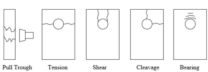
Optimum combinations of plate geometries and joining plates assemblies able to provide excellent structural integrity, reliability and efficient load carrying within composite joining system. Large parts of research work are mostly considering a single-bolted connection and investigate the failure mode, failure mechanism and the bearing strength. Most researchers have investigated the effect of varying single joint geometries such as hole diameter, laminate thickness, normalized width (W/d) and normalized end distance (e/d) ratio to in various lay-up systems that have great influence on ultimate bearing strength. There are five common failure modes that can occur in mechanically fastened joint in composite laminates as shown in Figure 1. Experimental studies by previous researcher mostly considered the bearing strength and associate failure modes in single-bolted connection. Esendemir [14[14] U. Esendemir, “Failure analysis of woven Glass-epoxy prepreg bolted joint under difference clamping moment,” Adv. Compos. Lett., vol. 17, pp. 165-175, 2008.] and Kontolatis [15[15] A. Kontolatis, “Failure of Composite Bolted Joints Made from Woven fabric GFRP Composite,” Guildford: University of Surrey, 2000.] had investigated the effect of geometrical parameters on the failure modes and failure loads of bolted joints in woven glass epoxy coupons with different clamping loads. As observed in the non-woven plates counterpart, the bearing strength of woven glass/epoxy laminate is increased by increasing W/d and e/d. Esendemir [14[14] U. Esendemir, “Failure analysis of woven Glass-epoxy prepreg bolted joint under difference clamping moment,” Adv. Compos. Lett., vol. 17, pp. 165-175, 2008.] also found that as clamping load increased, the ultimate bearing strength showed a significant increase and the failure modes were prone to net-tension in most cases. Kontolatis [15[15] A. Kontolatis, “Failure of Composite Bolted Joints Made from Woven fabric GFRP Composite,” Guildford: University of Surrey, 2000.] used a similar GFRP woven fabric system as used by Belmonte [16[16] H. M. S. Belmonte, C. I. C. Manger I., S. L. Ogin, P. A. Smith, and R. Lewin, “Characterisation and modelling of the notched tensile fracture of woven quasi-isotropic GFRP laminates,” Compos. Sci. Technol., vol. 61, no. 4 PG-585, p. 597, 2001.] in a double-lap bolted joint with clamping torque of 5 Nm. They found that the net-tension failure occurred in a plate with normalized width ratio, W/d ≤ 4. The crack initiated from the stress concentration at the notch tip perpendicularly to the loading plane. The mixed-mode of bearing and net-tension failures occurred with W/d= 5 and at sufficiently large e/d = 4. In Benoit’s experimental works [10[10] V. Benoit, J. Aucher, and L. Taleb, “Comparative study on the behavior of woven-ply reinforced thermoplastic or thermosetting laminates under severe environmental conditions,” Mater. Des., vol. 35, pp. 707-719, 2012.], this asymmetry caused the fastener to tilt in the bore hole and bolt-hole clearance contact pressure to become non-uniform through the plat thickness as tensile load was applied. Non-uniform stress distribution may cause the coupon to bend out-of-plane and these phenomena are referred as secondary bending as given in Figure 2.
The purpose of the current study is to explore the strength prediction of woven fabric KFRP by using XFEM approach, by implementing physically-based traction-separation as a constitutive model on bolted joints problems under temperature actions. The strength predictions are then validated against experimental dataset. Furthermore it is also to develop a methodology that is applicable to tensile failure at net-tension failure in bolted joints under temperature action. Several parameters were involved in bolted joint problems where analytical approaches seem unrealistic as huge numbers of parameters involved. The obstacle in finite element modelling of testing coupons associated with stress concentration is the occurrence of singularity ahead of crack tip in classical finite element method. Previously, this requires refined meshing ahead of notch tip in finite element modelling framework; however, the introduction of extended finite element framework (XFEM) techniques eliminates this requirement as it is driven by energetic approach. Ahmad et al. [9[9] H. Ahmad, A. D. Crocombe, and P. A. Smith, “Strength prediction in CFRP woven laminate bolted single-lap joints under quasi-static loading using XFEM,” Compos. Part A Appl. Sci. Manuf., vol. 66, pp. 82-93, 2014.,17[17] H. Ahmad, A. D. Crocombe, and P. A Smith, “Physically based finite element strength prediction in notched woven laminates under quasi-static loading,” Plast. Rubber Compos., vol. 42, no. 3, pp. 93-100, 2013.] has successfully conducted an Extended Finite Element Method (XFEM) framework approach in predicting joint strength of woven fabric CFRP composites with notched coupons and single-lap bolted joints, but as far as authors knowledge, studies on the strength prediction of this joint under elevated temperature action have rarely been reported.
2 EXPERIMENTAL STUDY OF WOVEN CFRP BOLTED JOINTS
The current paper builds on the previous works as follows; Firstly, the results of an experimental work on the bearing strengths of woven fabric KFRP single-lap bolted joints are presented. The work includes a variety of lay-ups and the effects of joint geometries (hole size and joint width), and under temperature condition. Secondly, the development of a three-dimensional finite element analysis (FEA) model, which incorporates the bolt-hole interaction and frictional load transfer in a representative way. Crack propagation is simulated using XFEM with independently determined input parameters. The results of the bearing strength predictions are then compared with experimental values.
2.1 Testing Coupons Preparation
The reinforcing fiber used in the current experimental work was plain weave kenaf fibers, one of the effective reinforcing natural materials that has excellent tensile strength (and modulus) and elongation at break. It also improved the mechanical properties of lightweight neat polymer. The weaving techniques used was by using handloom weaving machine as shown in Figure 3. The kenaf was weaved using handloom with good precision and care because during hand lay-up weaving process kenaf thread easy to break apart until achieving woven dimension required. Kenaf fibers are stored in dry conditions at Textile Laboratory, Universiti Tun Hussein Onn Malaysia (UTHM) to avoid hairy string. Kenaf fiber threads are available in various diameter sizes, available nominal sizes are 0.75 mm, 1.5 mm and 3 mm diameter size. The current work used 0.75 mm diameter size as reinforcing material in composite fabrication.
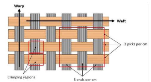
The process of yarn weaving into woven fabric layer are carried out until the desired layers were obtained. During kenaf yarn weaving, that are two orthogonal weaving directions, i.e. warp yarn (parallel to 0° loading direction) and weft yarn (perpendicular to 0° loading direction) as shown in Figure 4. The undulation region due to tow cross-over within warp and weft direction is known as crimping region. The unit of warp yarn is given as end per cm and fill is given as pick per cm. The size of woven fabric layer is approximately 240 x 250 mm2. Four lay-up types of woven fabric kenaf composite lay-up systems were studied in the present work. The epoxy resin system which controls the matrix dominated properties such as the transverse strength was reference as SP-84 were supplied and manufactured by Penchem Technologies Sdn Bhd, Penang. All of these woven fabric kenaf systems were fabricated in Fabrication Laboratory, UTHM. KFRP panels were cut using a diamond saw cutter to allow easy cutting and better edge finishing. The cutting process was carefully conducted to prevent any edges defect that may disturb the guage length capabilities.
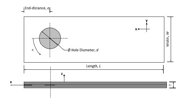
Circular hole with a constant hole diameter (d) of 5.0 mm were drilled using low helix, high-speed steel drill bits normally used for thermosetting polymers. The centre of hole drilling on testing coupons were applied with fixed normalised end distance, e/d of four in cross-ply lay-ups and six in quasi-isotropic lay-up to eliminate shear-out failure. The hole diameter coupons were inspected visually after drilling to ensure delamination and edge damage at the vicinity of notch edge were not formed. Coupon thickness and width of each testing coupon were measured by using a micrometre and a Vernier calliper respectively. The geometrical dimensions of testing coupon were given in Figure 5. The fastener systems (steel washers and steel bolts) used in this joint configuration systems have a nominal size of 5 mm or they are commercially identified as M5. It is essential to ensure the thread on bolt shaft was not in contact with composite coupons bore hole. The M5 steel washer has an internal and external diameter of 5.1 mm and 10.5 mm, respectively. Two steel washers were provided below the bolt head and above the nut respectively in both joint types.
2.2 Testing Series and Joint Assemblies
The test matrix of present work was shown in Table 1. The end distance was held fixed and the normalised joint width, W/d was varied in the range of 2 - 5. In the present work, the hole size, d = 5 mm and the clamped condition (T≈ 5 Nm) were studied. ASTM D3039B designation was referred in designing the test set-up for measuring quasi-static tensile strength properties of bolted joints. A quasi-static tensile loading on the bolted joints was carried out using an INSTRON machine. Each testing series investigated has at least three testing coupons as shown in Figure 6 and standard deviation of less than 5% to assure the reproducibility of testing results obtained. Each lay-up designation gave a total of 24 testing coupons, and a total of 96 testing coupons were tested throughout the testing series.
A single-lap bolted joint was assembled as illustrated in Figure 7. The joining coupon used in this configuration was aluminium coupon, where their dimensions were following joining KFRP plates attached. It was selected to provide a relative modulus to KFRP plate failure. As the aluminium coupons were reused of similar W/d series in the next testing work, it was customary to make sure that the aluminium coupons was not warping or if no longer remained plane, a new aluminium plate should be replaced. Current work used aluminium plates with yield strength of 100 MPa to avoid permanent deformation in aluminium plate to allow repetitive use. A spacer was placed at end tab during mechanical testing to avoid primary bending to occur during mechanical testing. Two steel washers are provided below the bolt head and above the nut respectively in both joint types. The bolt head should be large enough to reduce the pre-load relaxation. The installation torques studied was under clamped torque of 5 Nm. Torque wrench of suitable torque limits (0 -20 N m) is used to provide a sufficient and accurate amount of clamp-up. The torque wrench is calibrated prior to first use as indicated in manufacturer’s guidelines. Clamp-up is applied slowly to ensure that joints are not over-clamped. All joint assemblies were tested immediately after clamp-up to eliminate the effects from bolt relaxation.
2.3 Mechanical Testing
The current work were following Benoit, Aucher, & Taleb [18[18] V. Benoit, J. Aucher, and L. Taleb, “Influence of temperature on the behavior of carbon fiber fabrics reinforced PPS laminates,” Mater. Sci. Eng. A, vol. 517, no. 1-2, pp. 51-60, 2009.] works to study the effect of elevated temperature on KFRP plates. The temperature control system, including oven and a temperature controller, provides a stable temperature exposure during testing with operating temperature range from room temperature to 200 °C. Prior to mechanical testing, all testing plates were oven-dried at 70 ± 5 °C for 48 hours and preserve under waterproof environment so that the material samples can be considered as dry plates. A quasi-static loading was carried out on the single-bolted single-lap joint plate within 8 hours after oven drying. All mechanical testing were following standard ASTM D3039, ASTM D3039B and ASTM E21 of all lay-ups investigated given in Table 1. The single-lap joint differs from the pin load coupon by the present of lateral clamping provided by the bolt as shown in Figure 6. The diameter of the fastener and holes will vary with certain allowed tolerances. These tolerances are owned as bolt-hole clearances which influences in both stiffness and strength of composites bolted joints. Changes in the strength and in the failure mechanisms of open hole laminates and bolted joints were also investigated under elevated temperature conditions.
A quasi-static tensile loading on bolted joint was carried out using INSTRON testing machine located in Light Structure Laboratory. The cross-head speed used was 0.5 mm/min and the load cell capacity was 100 kN. Load and displacement data were recorded every second using a PC data logger. Mechanical tensile tests of bolted joints were carried out at a room temperature after cutting WKRP panels into testing coupons following designated geometry of the single bolted joint test. Bearing stress at failure in all testing lay-up series increased as a function of W/d, as expected in the lay-ups understudy. Again, the bearing strength at failures is given in expression (1),
where P max is the maximum load, t and d are the coupon thickness and diameter hole, respectively (equal to bearing area). As indicated previously in the literature review, testing coupons demonstrated fracture and failure in net-tension mode in single-lap bolted joint with low W/d, are more likely under a larger torque condition. This is likely because the washer compression under bolt load promotes more net-tension failure than the local bearing/net-tension failure under a finger-tight condition. The bearing/net-tension failure occurred in intermediate W/d was preceded by the local bearing damage. The net-tension failure showed more catastrophic failures than progressive manner in bearing failure mode. At larger W/d, there was a full crack failure in some laminate with peak-load corresponding to a trough-thickness compression fracture of the laminate at the washer edge.
3 FINITE ELEMENT MODELLING (FEM) OF WOVEN KFRP BOLTED JOINTS
3.1 Bolted Joint Geometry and Material Properties
FEM can be divided into three major stages, namely, pre-processing stage, processing stage and post-processing stage. Pre-processing stage is the essential stage where the input of FEA model takes place and it is comprised of four steps, i.e., modelling idealizations, element discretization (meshing), generation of material and geometry properties, and lastly, loading and boundary conditions. By using 3-D model, the frictional load is able to transfer frictional load between adjacent components explicitly. The current model was generated by using ABAQUS CAE Version 6.13 [19[19] Hibbit, Karlson, and Sorensen, Abaqus V6.13 User’s Manual and Theory Manual. Inc.]. The elastic properties of woven KFRP used in model are based on experimental work and smeared-out properties, as shown in Table 2. The modulus of elasticity, E and Poisson ratio, v of steel washers and bolts were given as 210 GPa and 0.33 respectively. On the other hand, aluminium was assigned with E = 70 GPa and v = 0.33. Both materials were assigned as isotropic properties. The complex fiber architecture effects on the sub-lamina behaviour in woven composite modelling are far from fully understood.
The elastic properties of woven KFRP lay-ups in single-lap bolted joint under investigation.
In unidirectional composite plates, the elastic properties can be calculated by using classical laminate plate theory (CLPT), however in woven fabric composite the calculation is not straight forward due to crimping regions. The “smeared-out” properties can be adopted by experimentally independent elastic properties and can be regarded as equivalent homogenous properties. Smeared-out approach provides better data representative if it was compared to non-woven system, because two separated piles laminate were replacing with single layer in woven reinforced polymer composite. In order to save the computational cost and effort, only a half of bolted joint configuration was modelled utilizing the advantages of its symmetry. The boundary conditions and the applied loads were assigned properly according to testing conditions as shown in the Figure 8. One end (side A) was held fixed support and the other end (side B) was assigned with the applied displacement. The y-symmetry were assigned to represent a half model. The geometry of composite coupons used in the current modelling work are following the experimental configuration as shown in Figure 9. The single-lap bolted joint model was applied with a torque of 5 N following application of torque range in the experimental work. The bolted joints configuration are following the dimension of composite coupons. Due to higher modulus of aluminium coupons, it was expected that the composite coupon were demonstrating larger secondary bending effects as shown experimentally.
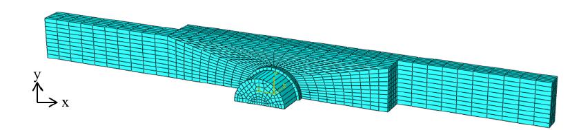
In the current single-lap joint model, five components were assembled as shown in Figure 10. Most researchers [e.g., [8[8] B. L. Agarwal, “Static Strength Prediction of Bolted Joint in Composite Material,” AIAA J., vol. 18, no. 11, pp. 1371-1375, 1980.]] reported that the washer and bolts were modelled as a single unit for simplicity, but in the current study, they were modelled separately to allow better representative for friction loading transfer. However, the bolt and nut were modelled in as a single part following to their actual geometries. The bolted joint system showed high non-linearity behaviour as a results of frictional load transfer, and it has to be physically representative of the experimental observations. The effect of frictional load transfer was more prominent with increasing bolt load. The effects of threaded region on the bolt shaft were ignored in current work as the bolt thread is only in-contact with aluminium coupons and not within composite bore hole, following the experimental observations. The mesh was refined near the hole area while away from the contact interaction the meshing was made coarser. The element type used was first-order 8-node liner brick element (C3D8I) with incompatible modes because only this element was compatible with XFEM framework as suggested by ABAQUS documentation. A sufficient meshing refinement was used to ensure that the strength prediction result was free from mesh-dependent. Meshing of the joint model implemented in ABAQUS CAE is shown in Figure 11.
The strength prediction of bolted joint models under room temperature condition were implemented within two loading steps; STEP 1 and STEP 2. In STEP 1, the bolted load was implemented and then followed by STEP 2 where a remote loading was applied, as shown in the Figure 12. On the other hand, under elevated temperature, the modelling were performed within three steps. In STEP 1, the clamping bolt (preload) was applied. The temperature was applied within STEP 2. This step was intended for inducing thermal load in the composite coupon. Finally, in STEP 3, the mechanical load were applied at its far-field-load. This implementation followed Santiuste et al.[20[20] C. Santiuste, E. Barbero, and M. Henar Miguelez, “Computational analysis of temperature effect in composite bolted joints for aeronautical applications,” J. Reinf. Plast. Compos., vol. 30, no. 1, pp. 3-11, 2011.] study on the computational analysis of temperature on a bolted joint. The procedure in assigning the thermal load in the model was similar to the experimental work where only composite coupons were exposed to temperature elevation. Predefined field temperature was applied with a thermal coefficient to have expansion as it was observed in the model of the bolted joint under elevated temperature. The longitudinal and transverse thermal expansion values used under elevated temperature condition were taken as α 1 = 1 x 10⁻⁶ and α 2 = 26 x 10-6 respectively. The values were taken based on the matrix-rich composite materials [20[20] C. Santiuste, E. Barbero, and M. Henar Miguelez, “Computational analysis of temperature effect in composite bolted joints for aeronautical applications,” J. Reinf. Plast. Compos., vol. 30, no. 1, pp. 3-11, 2011.]. It suggested that the thermal expansion is controlled by the matrix properties rather than the reinforcing fibers.
The bolt load of the joints can be implemented in a 3-D model to include the friction load transfer directly to the bearing area as slip occur. The load was transferred by friction at the early stage of the applied load. When the applied load, P exceeding 2µP bolt , the washer and joining coupons started to slide and eventually the bolt shank and bore hole came into contact. The friction coefficient, µ applied in model were assumed as 0.3, based on basic law of friction. From the experimental result the sliding load occurred at 250 N for torque condition (5 Nm), and the average load in the bolt associated to the woven KFRP test was found to be 833.33 N (P sliding < P bolt ) as a torque of 5 Nm applied to the bold. The procedure applying bolt load following suggestion by ABAQUS CAE 6.13. In order to apply the bolt load, it was required to apply pre-tension within bolt shank internal region during pre-load loading step (STEP 1), resembling to the clamping force applied to the nut. The applied bolt load were shown in Figure 13, and during the loading step (STEP 2) the bolt load were kept constant (fix at current length) as the composite plate hole borne with bolt shaft.
There are nine contact interactions applied in the model single-lap bolted joint configuration. The contact interactions were assigned with “master-slave” interactions, where the master regions were assigned upon surfaces with higher modulus properties. Meshing within slave regions should be finer than the master region counterparts, as required by ABAQUS CAE documentations. Each contact pair surfaces was assigned with friction coefficient of 0.1 for steel-steel (and steel-aluminium) interfaces and of 0.3 between steel-composite interface, similar values were used by McCarthy et al.[21[21] C. T. McCarthy, M. A. McCarthy, and V. P. Lawlor, “Progressive damage analysis of multi-bolt composite joints with variable bolt - hole clearances,” Compos. Part B, vol. 36, pp. 290-305, 2005.]. Surface interactions between joining parts explicitly incorporates stress transfer between joining parts resulting from bolt load to provide reliable strength prediction of bolted joints system. Surface contact interactions involved in current model were given in Figure 14.
3.2 Implementation of Constitutive Damage Law in FE Modelling
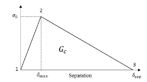
A physically-based constitutive law used in this study is based on the state-of-the-art fracture mechanics fundamentals to correlate a cohesive stress with a crack opening. This can be represented by a constitutive model of traction-separation material model law as illustrated schematically in Figure 15, embedded within a mesh of 3-D elements on bolted joint problems. A 3-D model is able to explicitly include friction load transfer, leading to a more representative simulation.
Damage initiation and propagation can also be simulated using an extended finite element method (XFEM). The advantages of the XFEM approach used in the present work are that, unlike the other approaches, it is physically based (and consistent with experimental observations of damage and fracture) and can be implemented using independently measured material properties. Figure 16 shows the region of assigned XFEM in composite coupon model and the crack domain around the hole edge where a crack was observed. The damage propagation at the hole model consists of a complex failure mechanism such as the fiber fracture tow, delamination and matrix cracking.
XFEM region is assigned in the woven fabric kenaf composite single-lap bolted joint composite model.
Most of researchers, e.g., [9[9] H. Ahmad, A. D. Crocombe, and P. A. Smith, “Strength prediction in CFRP woven laminate bolted single-lap joints under quasi-static loading using XFEM,” Compos. Part A Appl. Sci. Manuf., vol. 66, pp. 82-93, 2014.,12[12] B. Okutan, Z. Aslan, and R. Karakuzu, “A study of the effects of various geometric parameters on the failure strength of pin-loaded woven-glass-fiber reinforced epoxy laminate,” Compos. Sci. Technol., vol. 61, no. 10, pp. 1491-1497, 2001.,14[14] U. Esendemir, “Failure analysis of woven Glass-epoxy prepreg bolted joint under difference clamping moment,” Adv. Compos. Lett., vol. 17, pp. 165-175, 2008.] choose to study the bearing stress failure mode by determining the dimension joint and critical W/d. They paid a little attention on the net-tension failure that failed catastrophically, as they claimed that the failure can be avoided by providing a sufficient W/d ratio. However, due to large arrays of combination that may occur, there are no guarantee progressive bearing failure to occur. Additionally, the net-tension failure has higher tendency to fail in the multi-bolt with implying stress. It was found that a low W/d ratio was exhibiting to net-tension failure.
The maximum loads from the finite modelling analysis output were taken to obtain the bearing stress in predicting the failure. Two sensitivity studies had been carried out to determine the appropriate damage stabilization coefficient and the mesh size. This sensitivity study similar to Ahmad’s study [22[22] H. Ahmad, “Finite Element-based Strength Prediction for Notched and Mechanically Fastened woven fabric Composites,” University Of Surrey, 2012.] where it was reported that the damage stabilization coefficient was sufficient with a coefficient of 1 x 10⁻⁵ and there was no mesh-dependent on the strength prediction. The sensitivity study of mesh density was carried out at the region around the hole area of composite coupon as this area was our interest region and sensitive to the stress concentration. Meshing refinement study were carried out, concentrating region under washer in composite coupon as shown in Figure 17. The results of mesh sensitivity study on PQ4 W/d=5 single-lap bolted joint under room temperature is shown in Figure 17. It seems that the effect of mesh size on the strength prediction is negligible and this is expected because the approach is driven by energy.
Mesh sensitivity study effect on the strength prediction single-lap bolted joint PQ4 W/d=5 under room temperature.
The damage stabilization study on similar testing coupon as mesh sensitivity study was carried out to determine the appropriate damage stabilization coefficient. Figure 18 shows the effect of damage stabilization coefficient on the bearing strength prediction. It appears the output convergence has been achieved at the coefficient of 1 x 10⁻⁴. Hence, incorporation of smaller than these coefficient value gives unaffected predicted strength.
Current work used the constitutive model obtained from experimental result which was based on a traction-separation law. This constitutive model required two parameters, which was determined independently and regarded as material properties, i.e., un-notched strength,σσ o and fracture energy, G c . The material properties of all lay-ups investigated are given in Table 3. They were assigned within XFEM region along the net-tension plane. Damage initiation and propagation from the hole edge were modelled and were consistent with the failure patterns within the damage zone that were observed experimentally.
The elastic (and material properties) of all lay-ups system investigated are required as FEA modelling input. The in-plane modulus elastic properties (E x , E y ) were following ASTM D3039. Poisson’s ratio, v xy and G xy ) were following strain measurement by using bi-axial strain gauge and extensometer. The fracture energy, G c was measured using Single-edge notch (SEN) specimens. The methods recommended for the toughness determination of metallic materials ASTM E399-90 were followed where possible. The edge notches were machined using a jeweller saw and sharpened prior to testing with a fresh scalpel blade. It was necessary to establish the relationship between compliance and edge notch length before the toughness measurement could be made. Fracture energy, G c is measured by single-edge notch (SEN) technique using compliance method as given in expression (2). The compliance data measure three samples of each notch edge length before fourth-order polynomial was taken into account. The polynomial expression is the relationship between rate of change of compliance of edge notch length dC/da was differentiate and crack length, a.
From equation (2), t is the plate thickness of coupon laminate, P max is the maximum load at failure, C is the compliance and crack length SEN crack, a.
4 RESULT AND DISCUSSION
4.1 Typical Load-Displacement
A typical predicted load-displacement curve of the single-lap bolted joint woven fabric KFRP is shown in Figure 19. The damage plots at the selected points in the load-displacement curve (Figure 19) are shown in Figure 20. At the point (a) it showed the crack initiation, shown by the deviation from the curve linearity. From this point, a crack started to propagate until a maximum load was achieved at point (b). The coupon started to show a catastrophic failure shown by abrupt load dropping.
XFEM load-displacement curve for PX4 W/d=5 single-lap joint torque under elevated temperature.
Damage plot of XFEM result for PX4 W/d=5 in single-lap joint torque under elevated temperature with respect to load-displacement curve in Figure 19.
4.2 COMPARISON OF STRENGTH PREDICTION WITH FEA MODELLING
The dataset in Table 4 shows the bearing stress at failure for torque bolt condition under both room and elevated temperatures. It was found that the largest bearing stress is given in W/d = 5 in cross-ply (PX2 and PX4) coupons under room temperature. Similarly, under elevated temperature condition showed that all testing coupons were showing increasing trends with increasing W/d of similar lay-up respectively. The geometry of coupon width to hole size ratio affects the strength of composite coupon in a similar way to the notched problem. The increasing W/d to increased bearing stress at failure was associated with a larger unloaded region in the respective coupons. This finding is similar to the open hole problem with a larger hole size and correspondingly, the smaller coupon width to hole size ratio leads to the smaller notched strength. If it was compared with W/d=2, the bearing strength for PX4 lay-up at W/d=3, W/d=4 and at W/d=5 was increased by approximately 18%, 47% and 50%, respectively. On the other hand, in similar coupon thickness counterpart of PQ4, again comparing to W/d=2, at W/d=3, W/d=4 dan W/d=5, the bearing strength showed increment of 39%, 58% and 63% respectively.
The purpose of current study is to compare the strength prediction with experimental works. This enables laborious and cost reductions in designing structural application with composite coupons. The strength predictions of woven KFRP single-bolt joint were shown in Table 5 both under room temperature and elevated temperature. The XFEM modelling results were compared to experiment results in both room and elevated temperature action. In general, compared to the experimental results, the errors of the predicted bearing strengths were less than 35% under room temperature where most of the predicted strength were overestimated. On the contrary, under elevated temperature gives underestimated bearing stress at failure.
All single-lap joint configurations demonstrated net-tension failure in all W/d ratios as observed experimentally. Large coupon width (W/d) provided larger process zone failure prior to catastrophic failure and this contributed to the higher bearing stress at failure. Table 5 showed that the larger W/d specimens have higher the predicted bearing stress at failure under both temperature conditions, as observed experimentally. This agreement is consistent with the research observation by Kontolatis [15[15] A. Kontolatis, “Failure of Composite Bolted Joints Made from Woven fabric GFRP Composite,” Guildford: University of Surrey, 2000.]; increasing W/d and e/d increased the bearing strength. Further, his interrupted test at 90% load level showed extensive micro-damage event that occurred ahead of the notch edge. Nevertheless, current approach unable to predict bearing failures as these failures performed different failure mechanisms to give softening mechanisms beneath the bolt shank (predominantly fibre kinking and matrix compression) and not associated with stress raisers covered in the current constitutive model. This indicates that the physical-based modelling using constitutive modelling could predict failure, associated with the stress raiser ahead of the notch edge.
As seen in Table 5, a cross-ply lay-up laminate has higher ultimate bearing stress than a quasi-isotropic due to higher volume friction of 00 in the cross-ply laminate compared to the equivalent quasi-isotropic lay-up. The XFEM strength prediction results of PX4 lay-up has higher bearing stress value than the PQ4 and PA4 lay-ups. The error of the XFEM prediction and the experimental results for the PX2 was slightly higher than that of the PX4 lay-up. The thicker laminate shows slightly better prediction than the thinner laminate lay-up counterparts. Therefore, combination of between the thicker coupon and cross-ply lay-up (showed by PX4 lay-up) give better prediction than other lay-up perhaps it was not surprising. This may due to that the smeared-out properties were better represented in the thicker coupons as the coupon was associated with secondary bending. The similar behaviour was also observed in Ahmad et al. [9[9] H. Ahmad, A. D. Crocombe, and P. A. Smith, “Strength prediction in CFRP woven laminate bolted single-lap joints under quasi-static loading using XFEM,” Compos. Part A Appl. Sci. Manuf., vol. 66, pp. 82-93, 2014.] whose studied on a woven fabric CFRP composite coupon. The warping effect of secondary bending is given by a constant [Dij ], which is based on the constituent properties, current work averaged the material properties throughout the coupon thickness known as smeared-out properties. However, as the coupons tested were sufficiently thin, a plane stress formulation was still valid, therefore the smeared-out properties were giving a simplistic approach. On the other hand, the cross-ply lay-up laminate showed the better strength predictions than the equivalent quasi-isotropic lay-up in both temperatures action. The cross-ply sequence lay-up provided a better prediction in bending behaviour as reported by Ahmad [22[22] H. Ahmad, “Finite Element-based Strength Prediction for Notched and Mechanically Fastened woven fabric Composites,” University Of Surrey, 2012.].
Comparison work of XFEM model with experimental works in single-bolt joint woven fabric kenaf composites.
Buxton and Baillie [23[23] A. Buxton and C. Baillie, “A Study of the Influence of the Enviroment on the Measurment of Interfacial Properties of Carbon Fiber/Epoxy Resin composites,” Composites, vol. 25, no. 7, pp. 604-608, 1994.] reported that the bearing strength in polymer composites increased in elevated temperature as fiber matrix interface enhancement similar to fiber treatment and resin properties. The XFEM strength prediction gave the smaller error under elevated temperatures as shown in Table 5. The temperature leads to thermal expansion on composite coupons in longitudinal and transverse direction. The applied thermal expansion in XFEM were in good agreement with Santiuste et al.[20[20] C. Santiuste, E. Barbero, and M. Henar Miguelez, “Computational analysis of temperature effect in composite bolted joints for aeronautical applications,” J. Reinf. Plast. Compos., vol. 30, no. 1, pp. 3-11, 2011.] work under temperature action, however they used lamina properties and Hashin’s criterion for the degradation model. However the application towards stress concentration problem is found not suitable as most of the bolted joints failed in bearing failures. The bearing stress under elevated temperature shows increasing by 4 - 15% in all laminates with various W/d due toughening mechanisms of the matrix binder at the vicinity of the notch edge as reported by Buxton and Baillie [23[23] A. Buxton and C. Baillie, “A Study of the Influence of the Enviroment on the Measurment of Interfacial Properties of Carbon Fiber/Epoxy Resin composites,” Composites, vol. 25, no. 7, pp. 604-608, 1994.]. It was noted that the larger W/d showed the larger strength increment than the smaller W/d. Applying thermal expansion implemented with physically-based constitutive traction-separation law gave the small error in the strength prediction for all models under elevated temperature. It was found that the errors of 37% and of 15% under room and elevated temperatures, respectively indicating good agreement to all models validated with the experimental works.
Secondary bending (given in red dotted lines) in a single-lap joint (a) experimental observations (b) XFEM model.
Olmedo & Santiuste [24[24] Á. Olmedo and C. Santiuste, “On the prediction of bolted single-lap composite joints,” Compos. Struct., vol. 94, no. 6, pp. 2110-2117, 2012.] reported that the secondary bending added the tensile stresses due to the lifting of coupons and net-tension failure tended to occur compared to the double-lap bolted joints [25[25] H. Ahmad, A. D. Crocombe, and P. A. Smith, “Strength prediction in CFRP woven laminate bolted double-lap joints under quasi-static loading using XFEM,” Compos. Part A Appl. Sci. Manuf., vol. 56, pp. 192-220, 2014.]. Figure 21a shows the experimental observation of the secondary bending behaviour where bolt tilting occurs in single-bolt bolted joint. The similar behaviour was demonstrated in the XFEM modelling result as shown in Figure 22b. It occurred as the contact pressure between the hole edge and fasteners was not uniform through the coupon thickness. The secondary bending also changes the stress gradient when the bolt tilting and reduces the strength of the composite coupon [9[9] H. Ahmad, A. D. Crocombe, and P. A. Smith, “Strength prediction in CFRP woven laminate bolted single-lap joints under quasi-static loading using XFEM,” Compos. Part A Appl. Sci. Manuf., vol. 66, pp. 82-93, 2014.]. When this happened, the failure started to crack at the washer edge and tended to penetrate to composite surface. As a result, this give the premature failure as observed in the experimental work.
5 CONCLUDING REMARKS
The current project is conducted to study the strength prediction of bolted joint of the woven fabric KFRP under room and elevated temperatures. Temperature effects were incorporated in the model by using thermal coefficient and temperature values. The study includes the effect of lay-up types and the normalized W/d in bolted joints. Experimental observation on the bolted joint of KFRP coupons showed the crack initiation and propagation along the net-tension plane within the damage zone length prior to catastrophic failures. Another observation showed that under elevated temperature, increased bearing stress at failure was found due to matrix toughening, consistence with findings reported by other researchers. The strength prediction work of bolted joints was implemented within 3-D models for single-lap bolted joint explicitly incorporating the physically-based traction-separation relationship, contact surfaces interaction, friction coefficient and clamping load. The XFEM technique enables the cracks to be visibly tracked and it was driven by energetic approach to eliminate the mesh refinement ahead of crack tip. Good agreements between experimental results and XFEM modelling work was obtained, with discrepancies in the range of 4 - 35%. Better strength predictions were found in the woven fabric KFRP coupons of thicker and cross-ply coupons due to the better representative of “smeared-out” properties in cross-ply lay-up. Further, it is likely that the exhibition of secondary bending in single-lap bolted joint model may not be properly ideal in the thinner lay-up. Nevertheless, XFEM provides reasonably good predictions of KFRP composite bolted joints under elevated temperature.
Acknowledgement
The author would like to thank Research Fund E15501, Research Management Centre, UTHM in providing financial support for this project work.
References
-
[1]V. Mittal, R. Saini, and S. Sinha, “Natural fiber-mediated epoxy composites - A review,” Compos. Part B Eng., vol. 99, pp. 425-435, 2016.
-
[2]T. Nishino, K. Hirao, and M. Kotera, “X-ray diffraction studies on stress transfer of kenaf reinforced poly(l-lactic acid) composite,” Compos. Part A Appl. Sci. Manuf., vol. 37, pp. 2269-2273, 2006.
-
[3]H. Hajnalka, I. Racz, and R. Anandjiwala, “Development of Hemp Fibre Reinforced Polypropylene Composite,” J. Thermoplast. Compos. Mater., vol. 21, pp. 165-174, 2008.
-
[4]H. Anuar and A. Zuraida, “Improvement in mechanical properties of reinforced thermoplastic elastomer composite with kenaf bast fibre,” Compos. Part B Eng., vol. 42, no. 3, pp. 462-465, 2011.
-
[5]J. L. Abot, A. Yasmin, A. J. Jacobsen, and I. M. Daniel, “In-plane mechanical, thermal and viscoelastic properties of a satin fabric carbon/epoxy composite,” Compos. Sci. Technol., vol. 64, no. 2, pp. 263-268, 2004.
-
[6]H. Ku, H. Wang, N. Pattarachaiyakoop, and M. Trada, “A review on the tensile properties of natural fiber reinforced polymer composites,” Compos. Part B, vol. 42, no. 4, pp. 856-873, 2011.
-
[7]H. M. S. Belmonte, S. L. Ogin, P. A. Smith, and R. Lewin, “A physically-based model for the notched strength of woven quasi-isotropic CFRP laminates,” Compos. Part A Appl. Sci. Manuf., vol. 35, pp. 763-778, 2004.
-
[8]B. L. Agarwal, “Static Strength Prediction of Bolted Joint in Composite Material,” AIAA J., vol. 18, no. 11, pp. 1371-1375, 1980.
-
[9]H. Ahmad, A. D. Crocombe, and P. A. Smith, “Strength prediction in CFRP woven laminate bolted single-lap joints under quasi-static loading using XFEM,” Compos. Part A Appl. Sci. Manuf., vol. 66, pp. 82-93, 2014.
-
[10]V. Benoit, J. Aucher, and L. Taleb, “Comparative study on the behavior of woven-ply reinforced thermoplastic or thermosetting laminates under severe environmental conditions,” Mater. Des., vol. 35, pp. 707-719, 2012.
-
[11]C. Manger, “Failure of Notched Woven GFRP Composites: Damage Analysis and Strength Modelling,” Guildford : University of Surrey, 1999.
-
[12]B. Okutan, Z. Aslan, and R. Karakuzu, “A study of the effects of various geometric parameters on the failure strength of pin-loaded woven-glass-fiber reinforced epoxy laminate,” Compos. Sci. Technol., vol. 61, no. 10, pp. 1491-1497, 2001.
-
[13]P. A. Smith, “Carbon FiberReinforced Plastics - Properties,” Compr. Compos. Mater., pp. 107-150, 2000.
-
[14]U. Esendemir, “Failure analysis of woven Glass-epoxy prepreg bolted joint under difference clamping moment,” Adv. Compos. Lett., vol. 17, pp. 165-175, 2008.
-
[15]A. Kontolatis, “Failure of Composite Bolted Joints Made from Woven fabric GFRP Composite,” Guildford: University of Surrey, 2000.
-
[16]H. M. S. Belmonte, C. I. C. Manger I., S. L. Ogin, P. A. Smith, and R. Lewin, “Characterisation and modelling of the notched tensile fracture of woven quasi-isotropic GFRP laminates,” Compos. Sci. Technol., vol. 61, no. 4 PG-585, p. 597, 2001.
-
[17]H. Ahmad, A. D. Crocombe, and P. A Smith, “Physically based finite element strength prediction in notched woven laminates under quasi-static loading,” Plast. Rubber Compos., vol. 42, no. 3, pp. 93-100, 2013.
-
[18]V. Benoit, J. Aucher, and L. Taleb, “Influence of temperature on the behavior of carbon fiber fabrics reinforced PPS laminates,” Mater. Sci. Eng. A, vol. 517, no. 1-2, pp. 51-60, 2009.
-
[19]Hibbit, Karlson, and Sorensen, Abaqus V6.13 User’s Manual and Theory Manual. Inc.
-
[20]C. Santiuste, E. Barbero, and M. Henar Miguelez, “Computational analysis of temperature effect in composite bolted joints for aeronautical applications,” J. Reinf. Plast. Compos., vol. 30, no. 1, pp. 3-11, 2011.
-
[21]C. T. McCarthy, M. A. McCarthy, and V. P. Lawlor, “Progressive damage analysis of multi-bolt composite joints with variable bolt - hole clearances,” Compos. Part B, vol. 36, pp. 290-305, 2005.
-
[22]H. Ahmad, “Finite Element-based Strength Prediction for Notched and Mechanically Fastened woven fabric Composites,” University Of Surrey, 2012.
-
[23]A. Buxton and C. Baillie, “A Study of the Influence of the Enviroment on the Measurment of Interfacial Properties of Carbon Fiber/Epoxy Resin composites,” Composites, vol. 25, no. 7, pp. 604-608, 1994.
-
[24]Á. Olmedo and C. Santiuste, “On the prediction of bolted single-lap composite joints,” Compos. Struct., vol. 94, no. 6, pp. 2110-2117, 2012.
-
[25]H. Ahmad, A. D. Crocombe, and P. A. Smith, “Strength prediction in CFRP woven laminate bolted double-lap joints under quasi-static loading using XFEM,” Compos. Part A Appl. Sci. Manuf., vol. 56, pp. 192-220, 2014.
Edited by
Editor:
Publication Dates
-
Publication in this collection
24 June 2020 -
Date of issue
2020
History
-
Received
28 Feb 2020 -
Reviewed
22 Apr 2020 -
Accepted
28 Apr 2020 -
Published
04 May 2020