
Abstract
Steel plate shear walls are becoming popular for steel structures. In this study, the use of Steel Plate Shear Walls (SPSW) was discussed to increase the horizontal stiffness of reinforced concrete structures. It was aimed to fix the SPSW elements to the exterior of the building. ABAQUS models of SPSW applied 2D frame samples, which were tested in a previous experimental study, were created. Experimental and analytical horizontal load-top displacement curves were found to be in good agreement. In the study, ABAQUS models of a 6-story and 3D reinforced concrete building were also created. In models, SPSW elements were placed at the exterior of the building. The load capacities of the reinforced and non-reinforced building models were compared. The steel sheet thickness and the number of frame openings at which the SPSW element was placed were considered as the variable parameters.
Keywords:
Steel plate; shear wall; concrete; structure; lateral; rigidity; ABAQUS

1 INTRODUCTION
Many retrofitting methods have been developed for the strengthening of buildings that do not have sufficient lateral stiffness (Arslan and Korkmaz, 2007Arslan, M.H. and Korkmaz, H.H., (2007), What is to be learned from damage and failure of reinforced concrete structures during recent earthquakes in Turkey? Engineering Failure Analysis 14:1-22.). In the strengthening operations, jacketing of the existing reinforced concrete columns or the addition of reinforced concrete shear walls are generally preferred. In this case, the strengthening application is carried out inside the building and the repair of fine works is more costly than the cost of strengthening itself. Furthermore, the structure has to be evacuated during the strengthening process. This situation makes it difficult for the building owners or the inhabitants to make a decision whether to strengthen the building or not. In addition, if the building under consideration is an hospital or a dormitory building, it will be out of service during the strengthening process and this will result in additional costs due to operational and labor losses. For this reason, strengthening methods that will cause the minimum damage to the structure are in demand (Diri, 2015Diri, E. (2015). Strengthening of nonductile RC frames with thin steel plate shear walls. M.Sc. Thesis (in Turkish), Selcuk Univ., Konya, Turkey.). In this context, the method of strengthening of the buildings realized with the additions or applications at the exterior façade has become a new research area for the structural engineering community.
Ecemis (2018Ecemis S., (2018). Lateral rigidity improvement of deficient reinforced concrete structures with the use of user friendly systems. Phd Thesis, (in Turkish), Selcuk Univ., Konya, Turkey.) examined the different strengthening possibilities analytically by adding steel frames to the exterior of reinforced concrete framed structures. The author also included the contribution of the strengthening work and the added steel frame to the aesthetics of the building. Korkmaz (2012Korkmaz H. H., (2012). Seismic performance improvement of reinforced concrete frames not designed according to TDY 2007 with external shear walls, Scientific Research Project, Selcuk University, Project no: 11101012, 1-300, Konya, Turkey.), Unal (2012Unal, A. (2012). Strengthening of reinforced concrete frames not designed according to TDY 2007 with out of plane external shear wall. M.Sc. Thesis (in Turkish), Selcuk Univ., Konya, Turkey.) and Bahadir (2012Bahadir, F. (2012). Window opening effects in strengthening of RC frames with inadequate earthquake performance by using external RC shearwall. Ph.D. thesis (in Turkish), Selcuk Univ., Konya, Turkey.) examined the strengthening of 1/3 scale reinforced concrete test frames with reinforced concrete walls added to the façade. In the analytical study by Dere (2016Dere, Y. (2016). Assessing a retrofitting method for existing RC buildings with low seismic capacity in Turkey. Journal of Performance of Constructed Facilities 31: 1-7.), finite element models of 2-story and single-span test frames, which had been tested by Korkmaz (2012), were formed in ABAQUS (2020, Computer software, Dassault Systèmes) environment. The experimental and ABAQUS model analysis results were compared and found to be in good agreement. In the second part of the study performed by Dere (2016), 3-dimensional model of a 6-story reinforced concrete structure was created in ABAQUS environment with the use of solid elements. The contribution of strengthening with external reinforced concrete walls was analytically investigated. In the study therein, the assumptions, details and material models used in ABAQUS modeling were provided.
1.1 Use of Steel Plate Shear Walls for Lateral Rigidity
Steel Plate Shear Wall (SPSW) systems made of thin steel sheets can be used instead of diagonal cross elements used to provide horizontal stiffness in steel structures (Chen and Jhang, 2006Chen S.J., Jhang C., (2006), Cyclic behavior of low yield point steel shear walls, Thin Walled Structures, 44:730-738., Chen and Jhang, 2011, Qu et al., 2013Qu B., Guo X., Pollino M., Chi H., (2013), Effect of column stiffness on drift concentration in steel plate shear walls, Journal of Constructional Steel Research, 83:105-116., Lubell et al., 2000Lubell A.S., Prion H.G.L., Ventura C.E., Rezai M., (2000), Unstiffened steel plate shear wall performance under cyclic loading, Journal of Structural Engineering 126:453-460., Emami et al., 2013Emami F., Mofid M., Vafai A., (2013), Experimental study on cyclic behavior of trapezoidally corrugated steel shear walls. Engineering Structures 48, 750-762.). These systems are fixed to the column and beam members that limit the frame bay. The use of SPSW systems to increase the horizontal stiffness of reinforced concrete structures has been one of the hot topics studied recently (Choi and Park, 2011Choi I.R., Park H.G., (2011), Cyclic loading test for reinforced concrete frame with thin steel infill plate, Journal of Structural Engineering 137:654-664.). Korkmaz and Ecemis (2017Korkmaz, H.H., Ecemis, A.S., (2017) Seismic upgrading of reinforced concrete frames with steel plate shear walls. Earthquakes and Structures, 13:473-484.) examined the use of SPSW in reinforced concrete test specimens of 1/3 scale, 2-story and 2-span in their study. In the experimental study, they investigated the increase in the horizontal stiffness and the horizontal load carrying capacity of the reinforced concrete frame. In that study, a total of 7 frames, one of which was a reference bare frame, were strengthened with different SPSW configurations. It was envisaged in the study that SPSW system would be applied to the building’s exterior. Thus, strengthening operation will not be realized inside the building. Akın et al. (2016Akın E, Korkmaz S Z, Korkmaz H H, Diri E. (2016). Rehabilitation of infilled reinforced concrete frames with thin steel plate shear walls. Journal of Performance of Constructed Facilities 30: 1-8.), in their study, considered the strengthening of 1/3 scaled reinforced concrete test specimens with SPSW systems on both sides. In that study, it was envisaged that a brick wall was located in the span of frame and that SPSW plates were applied on both sides of this brick wall.
In this study, in order to increase the lateral stiffness of reinforced concrete framed structures, use of SPSW was examined. The contribution of SPSW application to be carried out at the façade of building was studied analytically. In the analytical part, the ABAQUS models of 2D frame specimens tested by Korkmaz and Ecemis (2017Korkmaz, H.H., Ecemis, A.S., (2017) Seismic upgrading of reinforced concrete frames with steel plate shear walls. Earthquakes and Structures, 13:473-484.) were created. The analytical models were created in parallel with the modeling principles performed in the study of Dere (2016Dere, Y. (2016). Assessing a retrofitting method for existing RC buildings with low seismic capacity in Turkey. Journal of Performance of Constructed Facilities 31: 1-7.) and experimental and analytical results were compared. Failure modes and deformation patterns obtained by experimental and analytical simulation were also compared. Validity of ABAQUS modeling approach was then discussed.
In the second stage of the research, the strengthening of a 6-story reinforced concrete structure with SPSW applied at the exterior facade was examined analytically. The horizontal base shear capacity and the increase in lateral stiffness obtained from the strengthened building were compared with the results obtained from the unstrengthened reference building.
2 EXPERIMENTAL RESEARCH
Experimental research was carried out within the scope of the studies by Korkmaz and Korkmaz (2015Korkmaz, S. Z., Korkmaz, H. H., (2015), Use of steel plate shear walls for the lateral rigidity improvement of reinforced concrete frame, Life-Cycle of Structural Systems: Design, Assessment, Maintenance and Management, Taylor & Francis Group, London, UK.) and Korkmaz and Ecemis (2017). In these studies, 1/3 scale, single-span and two-story reinforced concrete frames were produced. The test specimen represents the frame on an edge axis of the prototype building to be strengthened. Column dimensions were selected as 100 mm x 150 mm and the columns were placed to resist the horizontal load in the weak direction. Longitudinal reinforcement of 4ϕ10mm was used in the columns. Columns and beams did not have any regions of closely-spaced stirrups and all stirrups were placed at 100 mm intervals. Column stirrups were discontinued in the column- beam joint area. In Figure 1, the dimensions of the test specimen are given. All experimental members were subjected to reversed-cyclic horizontal loading simulating the earthquake excitation. Loading system was designed in such a way that 2/3 of the total horizontal load was applied to the upper floor and 1/3 to the lower floor. In the previous experimental stage, 7 specimens were tested. Apperances and the names of the specimens are given in Table 1. The first tested specimen was the reference sample (RF1) with no strengthening application. In the second test sample (S-Full), 0.3 mm thick steel plate was applied to the frame face. Two pieces of steel plate, one on the upper floor and one on the lower floor, were fixed to the outer surface of the sample. For the anchoring process, holes with a diameter of 9 mm at a depth of 80 mm were drilled in the center axis of the column or beam with an interval of 100 mm. Steel plates were fixed to the surface of the specimen by means of anchor rods with a diameter of 8 mm and epoxy. The steel sheet plate was fixed to the foundation by bending it at 90o at the foundation level.

Since the frame examined will be on the exterior of the building, it will probably contain a window opening. For this reason, in the third sample (S-Window), a window space was left in SPSW on both floors according to the general architectural dimensions. In the fourth sample (S-X), X-shaped steel plates were fixed to the front face of the frame opening. In the fifth test sample, circular holes with a special pattern were drilled in the thin plate (S-Perforated). Thus, it is aimed to give the facade an aesthetic appearance. Furthermore, due to the perforations, the yielding event may take place in the steel plate before the shear failure that may occur in the column. In the sixth sample (S-Beam), the size of the steel sheet was reduced to a certain extent and anchored only to the beams and foundation. In this way, the additional shear force transferred to the column was first transferred to the beam. In the final test sample, the SPSW is fixed to the inner side surfaces of the frame (S-Inner), not to the frame outside surfaces. Details about the experiments and numerical results were provided in Korkmaz and Ecemis (2017Korkmaz, H.H., Ecemis, A.S., (2017) Seismic upgrading of reinforced concrete frames with steel plate shear walls. Earthquakes and Structures, 13:473-484.).
3 3D FE MODEL OF THE TEST SPECIMENS AND ANLYSIS RESULTS
In this study, 3D FEM models of the above mentioned 7 test specimens were modelled in ABAQUS environment. The concrete members were modeled using 8 node linear solid elements with reduced integration points whereas the steel reinforcement was modeled using 2 node truss (bar) elements. The truss elements of the reinforcement were joined to the concrete solid elements using the embedded constraint available in ABAQUS. The translational degrees of freedom of the embedded truss nodes were constrained to the interpolated values of the corresponding degrees of freedom of the concrete solid element. The reinforcement was assumed to be fully bonded to the concrete elements. Concrete material was modeled using “Concrete Damaged Plasticity” option where concrete compression and tension damage models were defined.
The compressive uniaxial stress-strain relationship of concrete was first determined by cylinder tests then checked analytically using the stress-strain equation proposed in BS EN 1992-1-1:2004 by substituting the parameters obtained from the experiments, which were modulus of elasticity of concrete (Ecm=9300 MPa), concrete compressive strength (fcm= 14 MPa) and the corresponding strain (εcm=0.0025).
Although the axial forces were quite low in the experiments, there was some confinement effect that must be considered resulting from the stirrups. Therefore, the softening region of the unconfined stress-strain model was adapted to allow analytical load-displacement relation to become similar to the experimental relation of the reference frame. This stress-strain model was kept the same for all the other test simulations. The tension behavior was assumed to be linear up to the uniaxial tensile strength (ft) then determined using the exponential function:
where ft was assumed as 1.3 MPa. The stress-strain relation obtained from the steel reinforcement tension test is given in Figure 2-a. The stress-strain relation of the steel plate used in the retrofitting of the reinforced concrete frames was also obtained experimentally and the idealized graph is presented in Figure 2-b.

The foundation of the reinforced concrete frame was assumed to be fully constrained at the bottom. As was the case in the experiments, the numeric model was also constrained against out of loading plane displacements. The load transfer apparatus used in the experiments was designed to transfer actuator loading by a proportion of 2:1 onto the frame columns at the story levels. The apparatus was modeled using steel beam and truss finite elements. The FE model of the apparatus was tested to produce correct proportional loading on the frame model. The nonlinear pushover analyses were carried out by applying very small displacement increments onto the loading apparatus. In Figure 3, FE mesh of the first specimen RF1 and embedded reinforcement web are shown.
The steel plate used in various arrangements to retrofit RC frames was modeled by shell finite elements. The plate was physically attached to the RC frame by using implanted bolts. When simulating this phenomenon, truss elements (as bolts at the real bolt locations) were fully joined to the steel sheet sharing common nodes and embedded in frame elements similar to a reinforcing bar. The contact elements between the steel plate and concrete frame were also defined.

3.1 Comparison of Experimental And Analytical Results
Top displacement data versus total shear force obtained from nonlinear analyses were recorded. In Figure 4, the graphs of base shear-top displacement curves obtained by analytical modeling are compared. In Figure 5, the experimental and analytical shear force-top displacement curves are compared. The experimental results were obtained from Korkmaz (2012Korkmaz H. H., (2012). Seismic performance improvement of reinforced concrete frames not designed according to TDY 2007 with external shear walls, Scientific Research Project, Selcuk University, Project no: 11101012, 1-300, Konya, Turkey., 2016). The maximum horizontal loads obtained in analytical modeling and experimental studies are presented in Table 1.
Experimental and analytical results for RF1, S-Full, S-X, S-Window and S-Perforated specimens were consistent with regard to initial stiffness. There were differences in the experimental and analytical initial stiffnesses of S-Beam and S-Inner specimens
The maximum lateral load carrying capacities obtained from the analytical solution were close to those obtained from the experimental results. The largest differences in the results were observed in S-Inner and S-X specimens. The load-carrying capacities of the other analytical models were close to the experimental results.


3.2 Comparison of Damage Distribution and Failure Modes
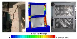
The damage and failure modes obtained in the experimental study were compared with the distribution of tensile damage obtained from analytical modeling. Figure 6 shows the distribution of the tensile damage in terms of colored contour maps obtained for the RF1 specimen. Pictures taken during the experiment indicating the cracks in the specimen were also given. The red zones in the analytical tension damage graph are the potential damage regions where tensile cracks are expected. It should be noted that the loading was cyclic in the experimental study and it is monotonic in the analytical study. Analytical and experimental base shear vs top displacement curves are compared in Figure 3-a

Comparison of experimental damage and analytical tensile damage distribution in sample RF1.
In the second sipecimen (S-Full), thin SPSW was added on one side of the reinforced concrete frame to improve the horizontal stiffness. The thickness of the applied steel sheet was 0.3 mm. SPSW was fixed to concrete columns and beams with anchorage rods of 8 mm in diameter at 100 mm intervals. The steel sheet was also bent in L form at the foundation level and anchored to the foundation by supporting it with an L-shaped steel profile. Details about the strengthening of the test sample using SPSW can be found in the relevant references which also presents the experimental results. Top displacement vs. base shear graphs of experimental studies and FEM analyses of S-Full specimen are given in Figure 5-b. In Figure 7, calculated Von-Mises stress distribution in SPSW element, under lateral loading is given. Colorful stress distribution on the deformed shape is useful for understanding the transfer of load from reinforced concrete frame to SPSW system and the contribution of SPSW to horizontal load carrying capacity.

Figure 8 shows the tension damage parameter distribution in the reinforced concrete frame for S-Full specimen on the deformed system. Colors approaching red shades indicate areas where the tensile damage is potentially high. In the same figure, the damage and cracking of the specimen during the test were given. The inclined shear crack that observed on the 1st floor column during the experiment was also observed as potential damage in FEM analysis.
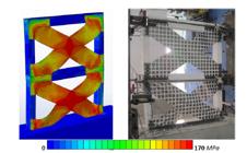
In the third specimen, X-shaped thin steel sheet system was created instead of SPSW system which completely filled the frame opening. It is envisaged that the X-shaped SPSW system will transfer the tensile forces diagonally to the frame corner nodes. System assembly and design details are available from the related references. Top displacement vs. base shear graphs obtained from experimental studies and FEM analysis are given in Figure 5-c. Figure 9 shows the Von Mises stresses occurring in the SPSW elements under horizontal loading. Diagonal steel strips experienced out-of-plane buckling in one direction while the other diagonal steel strips were under tensile forces. However, when the load changed direction, the buckled strip would be under tensile forces. In SPSW systems, buckling didn’t cause a failure mode in the strengthened specimen. In Figure 10, the distribution of Von Mises stresses and concrete tension damage in the reinforced concrete frame of the S-X specimen is presented together. In the same figure, the crack formation observed during the experiment was also compared.

The examined reinforced concrete frame represents a frame at the outer axis of the building to be strengthened. The SPSW system to be applied will also be located at the exterior of the building. The frame at the exterior of the building will probably have a window opening. Therefore, in the S-W sample, the window openings were created in the middle of the span of both floors. The experimental and analytical lateral load-top displacement curves of the S-W sample is given in Figure 5-d.
Von Mises stress distribution in SPSW system with window opening is given in Figure 11. On the same figure, the deformation observed during the experiment is given in order to show the similarity of the deformed shape obtained in FEM analysis to reality.

Figure 12 shows the analytical distribution of tensile damage in the reinforced concrete frame compared with the photographs taken during the experimental study. It can be said that the results obtained from the analysis carried out using the ABAQUS software are useful in identifying the regions of potential tensile damage.

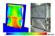
In order to add an aesthetic value to the SPSW system to be applied to the facade of the building, many circular holes were drilled in the SPSW of the S-Perforated specimen. The top displacement vs. base shear graphs obtained from experimental study and FEM analysis are compared in Figure 5-e. In Figure 13, the Von Mises stress distribution and the deformation pattern observed in perforated SPSW system is given together with the images displaying deformed shape of the specimen.

The tensile damage distribution and potential crack regions in the numerical S-Perforated sample are compared with the experimental crack and damage patterns in Figure 14.

In the “S-Beam Anch” specimen, the steel plates were fixed to the beams only. Thus, it was aimed that the shear forces caused by horizontal loading were carried only by the beams and the columns were not forced by additional shear forces. The SPSW element was only fixed to the beams in ABAQUS modeling in accordance with the experimental study. The load-displacement curve obtained in the analysis was compared with the experimental curve in Figure 5-f.
In Figure 15, the Von Mises stresses in steel plates are shown in the deformed model and compared with the deformation images obtained during the experiment. Tensile damage distribution obtained as a result of the analytical analysis of the reinforced concrete frame and the crack distribution in the specimen at the end of the experiment are compared in Figure 16.
The Von Mises stresses distribution and deformed shape of SPSW element of the “S-Beam Anch” specimen.

In the last test specimen ”S-Inner”, the SPSW elements were fixed to the inner surface of frame in the middle plane, i.e., not to outer surface of the concrete frame. ABAQUS modeling was performed to reflect the specimen behavior. The experimental and analytical lateral load-top displacement curves of the S-Inner specimen are given in Figure 5-g. In Figure 17, the Von Mises stress distribution of the sample is given in a comparative manner with the images of the deformed shape of the specimen taken at the end of the experiment. Figure 18 shows the tensile damage distribution of the S-Inner test sample.

The Von Mises stresses distribution and deformed shape of SPSW element of the “S-Inner” specimen.

4 3D BUILDING MODELS
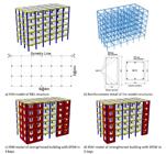
The results of the analytical study performed on 1/3 scale and 2D-plane frame models show an acceptable level of numerical agreement with the experimental results. In the second stage of the study, analyzes were carried out on a 3-dimensional, full scale 6-story building model. For this purpose, a symmetrical reinforced concrete building with insufficient lateral stiffness in both orthogonal lateral directions was designed. The architectural story plan, column application layout of the building, and facade views of the building were given in Figure 19.
Concrete quality was envisaged as C20/25. For the earthquake design, peak ground acceleration in the area where the building is located is assumed to be 0.4g. The columns in the building were designed to be square in shape. The design axes was equally spaced at 4 m. The building footprint is 24 m x 24 m with a floor height of 3 m. The column and beam dimensions are 350 mm x 350 mm and 250 mm x 500 mm, respectively. The slab thickness is 120 mm and there are no cantilevered slabs in the building. No reinforced concrete shear walls exist in the building and thus, the entire horizontal load is carried only by the columns. The vertical load analysis was performed in the building and the axial load level due to the effects of gravitational forces (1.4G + 1.6Q combination) compared with the column strength limit (AcxFck) set by the code (TS500, 2000; TBEC, 2018). For columns and beams, longitiduonalreinforcenment diameter was 16mm. 3 top and 3 bottom longitidunal reinforcements were placed to the beams. Columns contained 8xϕ16 reinforcements. 1 8 mm diameter stirrups at 150 mm intervals were placed in the columns and beams. Closely-spaced stirrups were not applied in the confinement regions. Only two column stirrups were placed at the beam-column joint.
The code limit is not exceeded in any column. For the longitudinal reinforcement, the ratio was accepted to be 1% for column and beam members. 8 mm diameter stirrups were placed in the columns and beams at 150 mm intervals. Closely-spaced stirrups were not applied in the confinement regions. The architectural story plan and column application layout of the building is given in Figure 18. Facade views of the building are also given in Figure 19.

The building model was created in the ABAQUS environment. The material model and solution assumptions are the same as the ones used in the plane frame modeling given in the previous section. The ABAQUS model for the building displaying the columns and beams is given in Figure 20-a. In addition, Figure 20-b displays the longitudinal reinforcement and stirrup distribution inside the concrete elements.
Since the building was symmetrical, only half of the building was modeled in the loading direction and the symmetry conditions were defined for the corresponding degree of freedoms of the nodes located at the axis of symmetry. Earthquake lateral force was applied to the building at the floor levels in triangular form distribution . As nonlinear analysis will be performed on the model building, displacement based loading was preferred and the horizontal push was applied in increments starting from zero. The analyses were continued until the last convergence point of the program. Convergence problems usually arise after reaching the maximum carrying capacity of the structure on a model of this size. For this reason, on the load - displacement curve, the curved region after the peak load, which shows a decrease in load carrying capacity, was not fully obtained in some models.
The first analysis model was the reference building (RM) without any strengthening. The other four models were strengthened with SPSW elements at building corners (Figure 20). The SPSW elements were placed at the building corners similar to the L-shaped specimen tested in the laboratory. The SPSW layout had two different configurations presented in Figure 20-c and Figure 20-d. Either four SPSWs (Figure 20-c) or two SPSWs (Figure 20-d) were placed at one floor of a building corner. In the model nomenclature, those containing 4 SPSWs are called “4B” and those containing two SPSWs are called “2B”. In addition, the SPSW thickness values in the models were selected as t = 1 cm or t = 0.5 cm.
In the models of strengthened buildings, SPSW elements were modeled in the same way as in the previous section. The SPSW elements were fixed to reinforced concrete columns and beams using 12 mm diameter anchorage bars. Panel openings with dimensions of 2100 mm x 2000 mm were created in the SPSW elements.
5 RESULTS
The curves of top displacement versus the total shear force obtained from the analyses are compared in Figure 21. The design earthquake force calculated for the reference building in accordance with the Turkish Seismic Code (TBEC, 2018) is indicated on the figure by a green dashed line. The crossing points on the curves corresponding to 1% drift at the building top are also indicated by a blue dashed line.
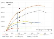
Table 2 summarizes some of the numerical data obtained from the analyses. The load carrying capacity (Fmax) of the models and the ratio of the load carrying capacity of the strengthened specimens to that of the reference building (Model/Ref.) are listed in the table.
The load carrying capacities of the buildings are improved between 7.5 and 2.7 fold with SPSW application. The thickness of the SPSW is effective in increasing the load capacity. This increase is more effective when more SPSW elements are used. There is 2.57 fold difference in strength between the model with 4 SPSW elements and the model with 2 SPSW elements with 1 cm thickness. This difference is 2.44 fold when the thickness of SPSW member used is 0.5 cm.
If the relationship between the number of SPSW elements and increase in strength is examined; in SPSW elements with a thickness of 1 cm, doubling the number of steel plates used results in a 2.26-fold increase in strength. This ratio of increase was 1.10 times with SPSW elements having 0.5 cm thickness. In Table 1, the total base shear force carried by the structure computed at the top displacement level corresponding to 1% drift (%1F), is also presented. The value in the fourth column (4), indicates the ratio of increase in stiffness of the building after the strengthening.At the top displacement corresponding to 1% drift, while the models with 4 SPSW and 2 SPSW elements with 1 cm plate thickness increases the stiffness by 5.72 and 2.74 times respectively, the models with 4 SPSW and 2 SPSW elements with 0.5 cm plate thickness increases the stiffness 4.24 and 2.30 times for the models with 4 and 2 SPSW elements, respectively.
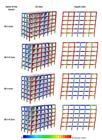
The Von-Mises stresses that occur in the fixed SPSW elements are given in Figure 22. The horizontal displacements are magnified by a scale factor of 3. The tensile damage distribution in the reinforced concrete members at the same displacement level is also given in Figure 23. In order to achieve this appearance, the steel plate elements were removed from the view.

6 CONCLUSION
In this study, the application of SPSW systems to reinforced concrete frames was analyzed analytically. The study consists of two parts. In the first part, the ABAQUS models of experimentally tested 7 reinforced concrete building frames were created. The results of the analyses of the models are summarized below.
-
The results obtained from the first stage analytical study herein and the numerical results obtained from the experimental study are in good agreement.
-
Deformation patterns and failure modes obtained as a result of ABAQUS analyses show great similarity with those obtained from the experimental study.
-
The potential crack locations determined in the analytical study were similar to the crack locations and directions of the actual experiment.
-
The SPSW systems substantially increase the horizontal load-bearing capacity and stiffness of the reinforced concrete frames.
-
Compared to the reference bare frame, the highest strength increase occurred in S-Inner and S-Full samples. The strength of these specimens was increased by more than 3 times. In other specimens, the strength increase was more than 2 times.
-
The assumptions, the material properties and the solution procedure adopted in the modeling of the first analytical section produce results close to real behavior and strength. Therefore, other models are created based on these reliable data.
In the analyses of the second analytical section, the SPSW system was applied on a 6-story 3D building model. Since the possibility of testing a building of this size is not yet possible or requires huge budgets, such a nonlinear analytical study becomes quite significant. The results obtained from the second part analyses can be summarized as follows.
-
The horizontal load bearing capacity of the reference building model calculated by a nonlinear analysis method was obtained to be close to the design earthquake force level. Therefore, the model building is not safe against earthquakes and needs to be strengthened.
-
In terms of horizontal load carrying capacity, the SPSW-applied models carry more loads ranging from 7.5 to 2.7 fold with respect to the reference model.
-
With the increase in sheet thickness and number of SPSW members used, load-carrying capacity increases.
-
The use of SPSW also significantly increases the horizontal stiffness of the reinforced concrete building.
The common results obtained from both analytical studies performed are as follows:
-
The SPSW systems which are properly designed and applied on reinforced concrete frame surface significantly increase the ductility and energy consumption capacity of the frame.
-
The implementation of SPSW systems will also limit the inter-story drift values of the building.
-
Since the use of SPSW systems increases the horizontal stiffness, they can also be used to change the dynamic properties of the structure. The stiffness increase will alter the natural frequency of the structure. In addition, the fundamental vibration modes can be changed by placing the SPSW system in certain frame bays within the structure.
The differences between the strengthening procedure with the implementation of SPSW systems outside the building and the other strengthening methods can be summarized as follows;
-
The SPSW systems do not increase the weight of the structure as much as the other strengthening methods.
-
The absence of concrete casting in the proposed strengthening technique accelerates the implementation of the strengthening. In addition, the lack of mold manufacturing will also accelerate the process.
-
During the implementation of SPSW strengthening, the building can continue to service its inhabitants.
-
The SPSW element transfers additional shear force to the column under horizontal loading. Thus, the columns to which SPSW elements are connected must have sufficient shear capacity. If the columns can accommodate this additional force, the SPSW elements on all floors can yield under horizontal loading before columns fail. This will consequently increase the ductility of the building.
References
- ABAQUS, (2020) [Computer software]. Dassault Systèmes, Waltham, MA.
- Arslan, M.H. and Korkmaz, H.H., (2007), What is to be learned from damage and failure of reinforced concrete structures during recent earthquakes in Turkey? Engineering Failure Analysis 14:1-22.
- Akın E, Korkmaz S Z, Korkmaz H H, Diri E. (2016). Rehabilitation of infilled reinforced concrete frames with thin steel plate shear walls. Journal of Performance of Constructed Facilities 30: 1-8.
- Bahadir, F. (2012). Window opening effects in strengthening of RC frames with inadequate earthquake performance by using external RC shearwall. Ph.D. thesis (in Turkish), Selcuk Univ., Konya, Turkey.
- Chen S.J., Jhang C., (2006), Cyclic behavior of low yield point steel shear walls, Thin Walled Structures, 44:730-738.
- Chen SJ, Jhang C. (2011), Experimental study of low-yield-point steel plate shear wall under in-plane load, Journal of Constructional Steel Research 67:977-985.
- Choi I.R., Park H.G., (2011), Cyclic loading test for reinforced concrete frame with thin steel infill plate, Journal of Structural Engineering 137:654-664.
- Dere, Y. (2016). Assessing a retrofitting method for existing RC buildings with low seismic capacity in Turkey. Journal of Performance of Constructed Facilities 31: 1-7.
- Diri, E. (2015). Strengthening of nonductile RC frames with thin steel plate shear walls. M.Sc. Thesis (in Turkish), Selcuk Univ., Konya, Turkey.
- Ecemis S., (2018). Lateral rigidity improvement of deficient reinforced concrete structures with the use of user friendly systems. Phd Thesis, (in Turkish), Selcuk Univ., Konya, Turkey.
- Emami F., Mofid M., Vafai A., (2013), Experimental study on cyclic behavior of trapezoidally corrugated steel shear walls. Engineering Structures 48, 750-762.
- Korkmaz H. H., (2012). Seismic performance improvement of reinforced concrete frames not designed according to TDY 2007 with external shear walls, Scientific Research Project, Selcuk University, Project no: 11101012, 1-300, Konya, Turkey.
- Korkmaz, S. Z., Korkmaz, H. H., (2015), Use of steel plate shear walls for the lateral rigidity improvement of reinforced concrete frame, Life-Cycle of Structural Systems: Design, Assessment, Maintenance and Management, Taylor & Francis Group, London, UK.
- Korkmaz H. H., (2016), Strengthening of nonductile RC frames with steel plate shear walls, Scientific Research Project, Selcuk University, Project no: 15201025, 1-300, 2015, Konya, Turkey.
- Korkmaz, H.H., Ecemis, A.S., (2017) Seismic upgrading of reinforced concrete frames with steel plate shear walls. Earthquakes and Structures, 13:473-484.
- Lubell A.S., Prion H.G.L., Ventura C.E., Rezai M., (2000), Unstiffened steel plate shear wall performance under cyclic loading, Journal of Structural Engineering 126:453-460.
- Qu B., Guo X., Pollino M., Chi H., (2013), Effect of column stiffness on drift concentration in steel plate shear walls, Journal of Constructional Steel Research, 83:105-116.
- TBEC, 2018, Turkey Building Earthquake Code, Republic of Turkey Ministry of Interior Disaster and Emergency Management Authority, Ankara, 2018.
- TS500, 2000, Requirements for Design and Construction of Reinforced Concrete Structures, Turkish Standarts Institue, Ankara, Turkey.
- Unal, A. (2012). Strengthening of reinforced concrete frames not designed according to TDY 2007 with out of plane external shear wall. M.Sc. Thesis (in Turkish), Selcuk Univ., Konya, Turkey.
Edited by
Editor:
Publication Dates
-
Publication in this collection
14 Sept 2020 -
Date of issue
2020
History
-
Received
05 May 2020 -
Reviewed
14 June 2020 -
Accepted
15 June 2020 -
Published
01 July 2020


