
Abstract
An experimental programme to investigate the notched strength of open-hole woven fabric kenaf fiber-reinforced polymer (WKRP) composite plates under quasi-static tensile loading. It was found that all testing coupons were failed in net-section, fracture initiated at the hole edge due to stress concentrations and propagated to the plate edge. A two-dimensional numerical modelling framework was developed following previously experimental series. A constitutive model of the traction-separation relationship was incorporated by using extended finite element model (XFEM) and cohesive zone model (CZM). Moreover, the effects of elevated temperatures and thermal expansion coefficient was incorporated within the modelling framework. Both modelling techniques were evaluated and compared, albeit to insignificant differences of maximum load output in both techniques, XFEM does not require apriori failure path compared to CZM. Good agreements between the predicted modelling work and measured notched strength were obtained, with discrepancies in the range of 0.4 - 25%, both displayed consistency in the net-section failures.
Keywords:
Textiles; Fracture; Finite element analysis (FEA); Open-hole plates

1 INTRODUCTION
Structural parts are mostly assembled by using mechanically-fastened joint such as bolted joints. Advantages of bolted joints are easy components disassemble for inspections, does not require surface preparation and relatively cheaper than adhesively-bonded joints. Nevertheless, a bolted joint requires hole drilling in composite plates. Existing of plate discontinuities such as open-hole caused stress concentration at the notch tip, therefore it is much expected that the fracture and failure of open-hole composite plates initiated from the notch tip. The stress is accumulated at the vicinity of notch edge with a factor of approximately three in isotropic materials, but larger stress concentration factor with higher laminate anisotropy. Therefore, the introduction of open-hole in composite plates leading to stress concentration to reduce the load-carrying capacity of tested plates. Stress concentration factors in composite materials are somewhat complicated dependent upon plate stacking sequence, and cross-ply lay-up may produce higher stress concentration factor than quasi-isotropic lay-up. Formation of cracks at the notch tips provides stress relief, and therefore, stress concentration is reduced substantially.
Recently, kenaf fibers have drawn attention among material researchers as an excellent reinforcing fiber in composite productions. Mohammed et al. (2015[1] L. Mohammed, M.N.M. Ansari, G. Pua, M. Jawaid and M.S. Islam, “A Review on Natural Fiber Reinforced Polymer Composite and Its Applications,” International Journal of Polymer Science Vol. 2015, pp. 1-15, 2015.) reported that kenaf fibers have high tensile strength, elongation at break, low cost, low density, and most importantly, kenaf fibers are an eco-friendly recyclable material compared to synthetic glass fibers. Various polymer types were used in a study by Anuar & Zuraida (2011[2] H. Anuar and A. Zuraida, “Improvement in Mechanical Properties of Reinforced Thermoplastic Elastomer Composite with Kenaf Bast Fibre,” Composites Part B: Engineering, Vol. 42, pp. 462-465, 2011.) that showed improvement in tensile, flexural and impact strength of kenaf fibers composites mixed with an epoxy-resin polymer. More commonly, kenaf fibers are weaved into two-dimensional woven reinforcement fibers, consisting of interlaced orthogonal tows. The woven kenaf fibres consist of two sets of interlaced warp (0°) and weft (90°) yarns. Abot et al., (2004[3] J.L. Abot, A. Yasmin, A.J. Jacobsen, and I.M. Daniel, “In-plane Mechanical, Thermal and Viscoelastic Properties of a Satin Fabric Carbon/epoxy Composite,” Composites Science and Technology, Vol. 64, pp. 263-268, 2004.) found that reinforcing composite with fiber lay-up, in general offers good dimensional stability in both warp and weft direction but low in-plane shear stiffness. Ku et al. (2011[4] H. Ku, H. Wang, N. Pattarachaiyakoop, and M. Trada “A Review on the Tensile Properties of Natural Fiber Reinforced Polymer Composites,” Composites Part B, Vol. 42, pp. 856-873, 2011.) reported that woven fabric composite materials offer advantages to promote drapeability, more economical (one woven layer is equivalent to two unidirectional plies), good impact resilience and fatigue resistances. Although two crossover point or “crimps” lead to a reduction in strength and stiffness, the overall mechanical properties are remaining adequate, addition to the ability of the woven arrest crack growth and excellent absorption at the two crossover points (Belmonte et al., 2004[5] H.M.S. Belmonte, S.L. Ogin, P.A. Smith, and R. Lewin, “A physically-based model for the notched strength of woven quasi-isotropic CFRP laminates,” Composites Part A, Vol. 35, pp. 763-778, 2004.).
Aziz & Ansell (2004[6] S.H. Aziz, and M.P. Ansell, The Effect of Alkalization and Fibre Alignment on the Mechanical and Thermal Properties of Kenaf and Hemp Bast Fibre Composites: Part 1 - Polyester Resin Matrix,” Composites Science and Technology, Vol. 64, pp. 1219-1230, 2004.) found out that polymer matrix promotes toughening effects in combination with natural fibers as exposed to elevated temperatures. Buxton & Baillie (1994[7] A. Buxton, and C. Baillie, “A Study of the Influence of the Enviroment on the Measurment of Interfacial Properties of Carbon Fiber/Epoxy Resin Composites,” Composites, Vol. 25, pp. 604-608, 1994.) reported that temperature action to composite coupon increased their bearing strengths as moisture was removed, similar to the influence of fiber treatment and resin properties. On the contrary, temperature action adversely affects the carbon laminate strength. The ductility nature of the matrix at high temperature promotes a localized and cumulative deformation of plastic above the contact area of the bolt hole along with buckling and debonding. There is a lack of study on material degradation of WKRP in particular to thermal effect, but there are some studies on other woven composites (Vieille et al., (2009[10] B. Vieille, J. Aucher, and L. Taleb, “ Influence of Temperature on the Behavior of Carbon Fiber Fabrics Reinforced PPS Laminates,” Materials Science and Engineering A, Vol. 517, pp. 51-60, 2009.)).
Finite Element Analysis (FEA) offers incorporation of a constitutive model within their modelling framework that requires a few material properties determined independently or otherwise, calibrated from literature datasets. A traction-separation relationship can be implemented within the FEA framework, which is a physically-based model from state-of-the-art fracture mechanics. The constitutive model can be implemented within two techniques, namely the extended finite element method (XFEM) and cohesive zone modelling (CZM). The former technique is able to track crack visualization from post-processing without explicitly assigned failure region. On the contrary, the latter technique requires apriori failure path retrieved from experimental observations. Lee and Ahmad (2019[8] S.Y. Lee, and H. Ahmad, “XFEM Modelling Of Single-Lap Kenaf Fibre Composite Hybrid Joints under Quasi-Static Loading,” Plastics, Rubber and Composites, Vol. 48(2), pp. 1-9, 2019.) have successfully implemented both techniques in hybrid bolted-bonded joints in woven fabric kenaf composites, and reasonable accuracy were obtained. This technique was then expanded to multi-bolted joints configurations of similar testing subsets, and good correlations with experimental observations and reasonable discrepancies were reported (Supar and Ahmad., 2018[9] K. Supar and H. Ahmad, “Strength Predictions of Multi-Bolted Joints in Woven Fabric Kenaf Composite Plates with Different Configurations using XFEM Frameworks,” Journal Trends in Textile Engineering & Fashion Technology, Vol. 2, pp 1-10, 2018.).
This work presents experimental and numerical approaches to deal with multi-holes of woven fabric kenaf-reinforced polymer (WKRP) composite plates under different elevated temperatures to include variables such as hole configurations, lay-up types, plate thickness and elevated temperatures. The current paper is structured as follows; Firstly, the experimental programme and results on notched strengths of WKRP coupons are presented. Next, the development of 2D FEA model is described, and the associated failure modes are compared with the experimental observations. The 2D FEA frameworks were carried out to determine the notched strength of open-hole WKRP composite plates by using the material properties determined independently. The notched strength predictions are then validated against experimental datasets.
2 EXPERIMENTAL OBSERVATIONS
2.1 Testing Series
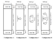
An experimental programme was developed to investigate the effect of elevated temperatures respective to the parametric investigation, i.e., lay-up types, plate thickness and numbers of multi-holes. Table 1 depicted the configurations of testing coupons series, respective to a single-row multi-holes plate. Notch configurations are set as symmetrical with the pitch distance is 15 mm. Figure 1 shows the investigated geometry of the testing coupons. Three testing coupons for each family of specimens have been manufactured and tested.
2.2 Material Preparations and Mechanical Testing
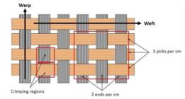
Kenaf fibers yarns were wrapped and stored in dry conditions to avoid hairy string. Current work used 0.75 mm in diameter of kenaf yarns as reinforcing material in composite fabrication. Weaving of kenaf yarns was carried out by using a weaving handloom machine with good precisions and care to form weaving pattern of plain weave. The woven fabric kenaf (276 tex) reinforcement with a packing density of 4 ends per cm (in warp direction) and 4 picks per cm (in weft direction) is shown in Figure 2. The size of a woven fabric layer is approximately 240 mm x 240 mm. The process of yarn weaving stage into woven fabric layers was repeated until required woven layers were obtained. Thermoset matrix (SP84 epoxy resin and SP76 hardener) with brand name of Penchem was used. The ratio of epoxy resin to hardener was 2:1 and using that ratio, the epoxy system can cure at room temperature for at least 24 hours. The epoxy system has a density of 1.14 g/cm3 and a glass transition temperature,T g of 90oC.
Prior to placing the first reinforcing fiber layer, the base of aluminium mold was sprayed with a silicone mold release to avoid from sticking with laid woven fabric kenaf layer. Epoxy resin and hardener was carefully poured and smeared on top of a woven fabric layer to avoid bubble formations within each layer and between adjacent layers. The stacking process was repeated to obtain the stacking sequence and plate thickness as specified in the testing series to produce wet woven fabric kenaf reinforced polymer (WKRP) composite panel. The uncured laminates were then placed on in-house Hydraulic Compression Molding Machine and compressed under a constant applied pressure of 40 psi (0.276 MPa) for 24 hours. Later, the hardened panel was removed from the aluminium molds. The composite panel dimension was specified as 240 mm x 240 mm before cutting into smaller WKRP coupon size.
The testing coupons with fiber volume fraction (by weight) of 18% were cut from a WKRP panel were drafted by using AUTOCAD to allow 3 mm shrinkage between cutting edges for matrix shrinkage. At least three testing coupons for each testing families were prepared. All coupons produced from a panel were labelled with lay-up types (cross-ply (PX) or quasi-isotropic (PQ)), and numbers of woven fabric layers (2 or 4 layers). The composite panel was cut into testing coupon size of 25 mm x 250 mm each including allocation for 50 mm length end tab at both ends for mechanical testing later. The cutting process was carefully conducted using a Bosch jigsaw machine to prevent delamination or damages along the plate edge, otherwise any defect could disturb tension strength of the testing coupon. A hole diameter was held fixed to 5 mm, and it was introduced into testing coupons by using a low helix and high-speed drill that is suitable for drilling thermoset polymer. A sharp-angled drilling bit was used to reduce end pressure and to minimize matrix burning and hole edge defects. A steel jig was used to hold the testing coupon in place during drilling. Drilling process was carefully conducted, and all drilling holes were inspected visually to make sure there is no hole break-out. Plate width and plate thickness of the testing coupons were measured by using Mitutoyo vernier calliper (with the accuracy of ±0.03 mm) and Mitutoyo micrometer (the accuracy of ±0.002 mm), respectively.
The method to expose testing coupons under elevated temperature is following Vieille et al., (2009[13] B. Vieille, J. Aucher, and L. Taleb, “Woven Ply Thermoplastic Laminates under Severe Conditions: Notched Laminates and Bolted Joints,” Composites Part B, Vol. 42, pp. 341-349, 2011) who studied the effects of elevated temperature on woven fabric carbon fiber reinforced polyphenylenesulfide (PPS) laminates. The temperature control system, including oven and a temperature controller, provides a stable temperature environment. The operating temperature ranges from room temperature to 200°C. Prior to mechanical testing, the testing coupons were oven-dried under elevated temperature (100°C, 150°C or 200°C) for 48 hours and preserved in a waterproof environment so that the material samples can be considered as being dried. Mechanical testing of all open hole testing coupons was carried out within one hour after removed from drying oven (ASTM E21 specified that testing coupons should be conducted within 8 hours following the oven drying) to control the consistency of temperature effect. All the tests followed the standard of ASTM D3039, ASTM D3039B and ASTM E21 (standard test methods for elevated temperature tension tests of metallic materials). The open hole test was carried out with a variation of multi-holes (i.e., one, two and three holes).
Mechanical testing was carried out under quasi-static tensile loading on testing coupons using an Instron UTM machine, following ASTM D3039 (Standard test method for tensile of polymer matrix composite material properties). Both end tabs with a length of 50 mm on each end sides were properly gripped to avoid slippage during testing. A crosshead speed of 0.2 mm/min, and a load cell of 100 kN were used. Load and strain data were recorded at one-second intervals using a PC data-logging Instron package. The ultimate loads of all testing series were obtained from data-logger, and the corresponding notched strength is obtained by diving ultimate load, Pmax with the measured cross-sectional area of testing coupons.
2.3 Un-notched and Notched Strengths and Experimental Observations
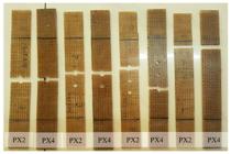
The un-notched and notched strengths of all testing series under elevated temperature (100ºC, 150ºC and 200ºC) are given in Table 2. The cross-ply (PX4) lay-ups and quasi-isotropic (PQ4) lay-ups have an equivalent nominal plate thickness, given as 4 mm (corresponds to four woven fabric kenaf layers). As expected, the un-notched testing coupons series had the highest plate strength as there is no stress concentration within plate continuity. Figure 3 shows the images of both lay-up types that demonstrated net-sectional failure along the net-section plane. Even so, the cross-ply series (PX4) performed better exhibition of strength compared to the equivalent quasi-isotropic lay-ups (PQ4) in the unidirectional tensile test. Cross-ply lay-ups has an advantage of more 00 fiber volume as tensile loading is applied parallel to 0º fiber direction to provide better loading resistance. On the contrary, the quasi-isotropic series has less 00 fibre directions to perform less resistance to the applied load. However, the quasi-isotropic may have advantages when it is subjected to a multi-directional loading since it has the properties closer to isotopic behavior. Similar findings were reported by Romanye and Ahmad (2016[11] A.H. Romanye, and H. Ahmad, “Notched Strength of Woven Fabric Kenaf Composite Plates with Different Stacking Sequences and Hole Sizes,” MATEC Web of Conferences, Vol. 78, pp. 1-5, 2016.) where the quasi-isotropic lay-up had slightly lower peak load, and correspondingly lower notched stress at failure than the cross-ply counterparts.
The Un-notched and Notched Strengths of Experimental WKRP Plates under Different Elevated Temperatures

The net-sectional failure of cross-play lays up with different plate thickness (between PX2 and PX4) is shown in Figure 4, where the thicker plate was as a result of larger numbers of woven kenaf layers. It was found that the thicker testing coupon (i.e., PX4) gave slightly better notched strength compared to PX2. This is due to the fact that the thicker coupons contribute additional fiber-matrix interfacial strength better than the thinner coupons; however, the value of notched strength between both plate thicknesses are very close. The thicker plates are associated with more woven fabric layers within polymer matrix providing better resistance against micro-damage events (i.e., fiber delamination and fiber fracture) of composite laminates. The similar findings were reported in Belmonte et al., (2004[5] H.M.S. Belmonte, S.L. Ogin, P.A. Smith, and R. Lewin, “A physically-based model for the notched strength of woven quasi-isotropic CFRP laminates,” Composites Part A, Vol. 35, pp. 763-778, 2004.); as the plate thickness increased, higher resistance to delamination of fibre event (fibre delamination and fibre fracture) were found. However, civil engineering sectors usually employed the thicker plates. Therefore the effect of plate thickness has a substantial role in the structural behaviour study of using fibre-reinforced composite plates.
Three holes configurations were investigated in the current study, i.e., one hole, two holes, three holes and un-notch plates. In the current study, all holes configurations were arranged in a single row with a similar gauge length area of all series investigated. It is much expected due to the absence of stress concentration within the unnotched plate gives better strength than other open-hole plates. The effects of number of holes in the testing coupons are insignificant as the failure path occurred within the net-sectional path. It was found that the peak load in PQ4 decreased as the number of holes are getting larger (from one hole to three holes), but not much convincing to these effects can be justified. On the contrary, the cross-ply lay-up lay-ups showed inconsistent trends with a higher number of holes. It is expected that a larger number of holes associated with larger hole elongations that may perform lesser ultimate load. However, as self-similar cracks were exhibited, leading to less significant effects from hole configurations. Note that for the current multi-holes arranged in a single row, the effect of eccentricity is negligible.
There were no consistent trends of increasing or decreasing as temperatures increased from 100ºC to 200ºC. However, in general, the notched strength of woven fabric composite plate increased as temperatures increased from 100ºC to 150ºC. Then, there is a slightly decreased notched strength as temperature exposure increased from 150ºC to 200ºC. As stated by Hollaway (2010[12] L. C. Hollaway, “A Review of the Present and Future Utilisation of FRP Composites in the Civil Infrastructure with Reference to their Important In-service Properties,” Construction and Building Materials, Vol. 24, pp. 2419-2445, 2010.), at a temperature between 101ºC - 150ºC, fibre-reinforced polymer tends to soften at slightly lower temperatures of these ranges. Another study by Vieille et al. (2011[10] B. Vieille, J. Aucher, and L. Taleb, “ Influence of Temperature on the Behavior of Carbon Fiber Fabrics Reinforced PPS Laminates,” Materials Science and Engineering A, Vol. 517, pp. 51-60, 2009.) reported that matrix ductility occurred at a temperature of 120ºC.
3 FINITE ELEMENT MODELLING
3.1 Pre-processing Stage
The geometry of multi-holes WKRP plate model is following experimental testing coupon as shown previously in Figure 1. In this study, the end-tabs for gripping during mechanical testing were ignored for modelling simplicity. A plate width of 25 mm and a gauge length of 130 mm were modelled with a constant pitch spacing of 15 mm, plate configurations depending upon testing series. Current work idealized open-hole WKRP plates as 2D model where the only in-plane plate was explicitly modelled. The plate thickness is not explicitly modelled but the out-of-plane direction (associated with plate thickness) allowed to smeared stresses throughout the plate thickness. Plane strain formulation is used as some testing plates are considerably thick, i.e., the nominal thickest plate is 4 mm. The 2D models provide faster computational time with assumptions that there is no significant deformations and exhibition of self-similar cracks throughout the plate thickness as seen from experimental observations. Therefore, 2D models were sufficient to represent the crack growth in open-hole plates. Due to the advantage of plate symmetry (i.e., y-symmetry), a half-model was adopted to save computational time and costs without sacrificing results accuracy.

The current work implemented two numerical techniques, i.e., extended finite element method (XFEM) and cohesive zone modelling (CZM). In the first technique, the XFEM region as the crack domain was assigned at the vicinity of the notch tip, as shown in Figure 5. This region was selected as crack occurred within the net-sectional plane (i.e., perpendicular to applied loading direction). Although XFEM formulation does not require a failure path to be known earlier, assigning XFEM within crack area provides faster convergence. The remaining regions were assigned as non-XFEM regions. On the contrary, CZM techniques require the failure path to be known earlier prior to modelling work. It was obvious from experimental observation that the plate failures occurred within the net-sectional plane; therefore the cohesive zone should be modelled along that plane, as shown in Figure 6. The thickness of 0.2 mm was partitioned along the net-sectional plane following ABAQUS suggestion that small thickness of cohesive zone has to be provided.

CZM region assigned at the vicinity of the notch tip of 2-D model (cohesive zone is enlarged for visual clarity).
Element discretization with finer mesh can provide better predictions but requires expensive computational times. In the current work, the areas at the vicinity of the notch tip were made finer as these areas were the regions of interest due to stress concentration, as illustrated in Figure 7. The regions further away from the notch tip were made coarser. All elements in XFEM technique was assigned as plane strain element, given as CPE4 from ABAQUS element designation. On the contrary, the cohesive element (i.e., COH2D4) was used within the cohesive zone of CZM technique and the remaining non-cohesive regions were assigned with plane strain element (CPE4). Cohesive zone element was very sensitive to the element aspect ratio; therefore, the similar in-plane element sizes were carried out, as shown in Figure 7. A single element series was assigned within the cohesive zone perpendicular to applied loading. Mesh refinement density of 30 x 30 was made on the notched region area, while 10 x 10 meshing density was assigned to the other regions.

Figure 8 shows the boundary conditions and loading implemented in all testing plates for both techniques, XFEM and CZM. The one end was held fixed, and the other end was assigned with the applied traction. This was to simulate the quasi-static tensile loading as tested experimentally. Bear on mind that during experimental work, the loading rate was fixed at 0.2 mm/min. Due to plate symmetry, the y-symmetry boundary was assigned in the y-symmetry plane, as shown in Figure 9.
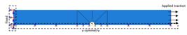
Boundary conditions and loading implemented in current model for both techniques, XFEM and CZM
Table 3 provides the elastic properties of all testing lay-ups under investigation; these properties were determined from experimental work following the relevant code of practice. Additionally, Table 4 gives the material properties (i.e., un-notched plate associated to maximum cohesive stress, σ o and fracture energy value, G c .) of similar lay-ups to be implemented within the traction-separation relationship as a constitutive model. These elastic and material properties were taken from Supar and Ahmad (2018[9] K. Supar and H. Ahmad, “Strength Predictions of Multi-Bolted Joints in Woven Fabric Kenaf Composite Plates with Different Configurations using XFEM Frameworks,” Journal Trends in Textile Engineering & Fashion Technology, Vol. 2, pp 1-10, 2018.) as a subset of similar lay-ups investigated, obtained from independently determined experimental set-up and regarded as “homogeneous” properties. The XFEM formulation adopted the maximum principal stress (MAXPS) where crack occurred orthogonally to maximum principal stress. On the contrary, the CZM assigned the maximum stress formulation (MAXS) within the cohesive zone region that requires stiffness constant of E nn and K ss to be incorporated, associated to the slope of the bilinear curve in the constitutive model incorporated. In this case, the E nn of 5000 N/mm and K ss =1000 N/mm were adopted. To take into account the effects of temperatures, incorporation of temperature degrees (i.e., 100ºC, 150ºC and 200ºC) and isotropic thermal expansion coefficient, α = 62.83 x 10⁻⁶ /°C of epoxy resin was taken from Dash (2016[14] M. Dash, “A Study on Thermal Characteristics of Epoxy Composites Filled with Natural Fiber and Particulate,” Rourkela (India): National Institute of Technology. Vol. 31, 2016.). These coefficients were adopted due to WKRP plates has resin-rich composites (V f =17%), suggesting that the plate deformation is dominated by resin response.
3.2 Modelling Results and Discussions
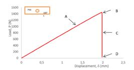
A typical load-displacement curve from post-processing output of XFEM technique is given in Figure 9, while the associated damage plots from Point A to D is given in Figure 10. Crack initiated at the notch tip due to stress concentration at the notch tip resulting from plate discontinuity at point A. This point is associated with matrix cracking, and the delamination takes place until reaching Point B. The interval from Point A to B is known as process zone length, which the extensive micro-damage event (i.e., delamination, matrix cracking and fiber fracture) took place prior to the catastrophic failure. During experimental observations, the existence of micro-damage events was heard as screeching sound due to matrix (epoxy resin) cracking. At Point B, the maximum load is given as the crack size reaches approximately the radius of hole size. Normally, the maximum load is exhibited as fiber tow fracture exceeding the process zone length, associated with the ultimate strength borne of reinforcing fibers. Soon after reaching Point B, the catastrophic failure takes place. From points B to D, the load suddently dropped where at Point D showed full plate separations. The cracks in XFEM model can be tracked visually from the graphical animations. The crack formation is given as STATUS XFEM from field output where it gives a value of 1 once the crack has occurred.

Two sensitivity studies had been carried out to determine the appropriate mesh size, and a damage stabilization coefficient was used. Mesh refinements study were carried out in one hole of PX4 lay-up under 200°C exposure. The meshing variation was made at the region around the notch tip (as shown in Figure 11) as these regions are associated with a stress concentration to initiate the crack formation and propagations. The remaining regions further away from the notch vicinity were held constant. The strength prediction results respective to number of mesh at the vicinity of crack tip is given in Figure 11. It was found that the strength prediction is independent of mesh refinement as XFEM model incorporates traction-separation relationship to promote cracks development from an energetic approach. Nevertheless, finer mesh requires expensive computational efforts to obtain a numerical convergency.

Mesh refinement study at the vicinity of the notch tip in one hole of PX4 lay-up under 200°C exposure.
A sensitivity study of damage stabilization coefficient used in this XFEM modelling framework is shown in Figure 12, taken from three-hole PQ4 under the elevated temperature of 100°C. High damage stabilization coefficient gave excessive and non-physical strength prediction results. It was found that the damage stabilization of 1 x 10⁻⁴ showed an acceptable consistency of notched strength. Smaller damage stabilization coefficient is associated with longer computational times due to difficulties in obtaining convergency; therefore, a threshold value to provide a consistent notched strength has to be determined. Thus, the damage stabilization coefficient of 1 x 10⁻⁵ is adopted in all models to provide reliable strength prediction works.

The strength predictions of all testing series investigated are tabulated in Tables 5 and 6 under room and elevated temperatures using the XFEM and CZM techniques, respectively. Approximately similar trends and strength predictions values were obtained in both the XFEM and CZM models from all testing series investigated. Both techniques used traction-separation relationship as a constitutive model; therefore, the similar strength prediction outputs obtained from both techniques are perhaps not surprising. The major advantage of using XFEM is that it does not necessarily require a crack path to be assigned within the modelling framework; the crack can be tracked and visualized from post-processing output. On the other hand, CZM requires a crack path to be modelled within a sufficiently thin cohesive zone region and placed in the model following the crack growth path observed from experimental work. Moreover, the convergence of post-processing results from the latter technique is sensitive to aspect ratios of the cohesive element.
It was found that the cross-ply lay-up promotes better average notched strength predictions than that of the quasi-isotropic counterparts with 5% discrepancy (opposed to 10% in the latter lay-up). The current modelling approach used “smeared-out” properties, which were independently measured through a small-scale experimental set-up and regarded as homogeneous properties. Thus, implementation of homogeneous properties is better represented in the cross-ply lay-up than that of the quasi-isotropic lay-ups. Respective with the plate thickness, the thicker plate provides better agreement than the thinner plate counterparts; the latter lay-up gives discrepancies up to 25%. Larger numbers of layers repetition and cross-plies have led to better representation of homogeneous properties as modelling approach. Moreover, the fracture energy value is better represented in the thicker plates as it is contributed by the additional resistance of the interfacial strength of the neighbouring layer to reduce the occurrence of damage resulting from delamination.
Strength prediction results of testing series investigated from XFEM technique and discrepancies with experimental datasets.
Strength prediction results of testing series investigated from CZM technique and discrepancies with experimental datasets.

Less good predictions were obtained for the hole configurations (discrepancy up to 12.5%), partly due to assumptions that 2D modelling ignores the out-of-plane deformations. Theoretically, hole in a plate elongates proportionately to the plate thickness, the thicker plate exhibits smaller hole elongation. This phenomenology is more apparent with a larger number of holes in a plate, which is associated with wider hole elongations. But this is not explicitly modelled within 2D modelling framework. Figure 13 provides a graphically strength prediction of PX4 with one hole under different elevated temperature. It is worth noting that the notched strength prediction is not much different with the temperature exposures. The effect of temperatures may not be well-represented in 2D modelling framework, partly because the deformation within the plate thickness is not explicitly modelled. Nevertheless, the notched strength of open-hole plate is better represented by incorporation of orthogonal thermal expansion properties (α1, α2), where α1 is the thermal expansion coefficient in the longitudinal direction (usually dominated by reinforcing fibers), and α2 is the thermal expansion coefficient in the transverse direction (usually dominated by matrix properties). However, thermal expansion values for kenaf fiber composites is not yet available in the literature.
4 CONCLUDING REMARKS
Testing series to investigate the notched strength of open-hole WKRP composite plates with variation of elevated temperatures was developed, and all testing coupons exhibited net-sectional failures due to the stress concentration from the notched edge. Later, the experimental set-up is modelled within 2D modelling framework by using XFEM and CZM techniques. Micro-damage events within the process zone length prior to catastrophic failures from experimental observations are represented by incorporating the traction-separation relationship as the constitutive model, where the independent material properties were used. Inclusion of temperature values and thermal coefficient are also included within the model to take into account the temperature variation. The results of prediction both in trends and values obtained from XFEM and CZM techniques were not much different, which might be due to the similar constituve model for both techniques. However, CZM requires the crack path to be modelled explicitly from experimental observations. The combination of cross-ply and thicker plates gives excellent prediction due to the implementation of “homogeneous” properties, which is best represented in the plate with more repetitive layers and thicker plates. Less good agreement was seen with the plates with a larger number of holes. This was partly because the wider hole elongation may not well represented within 2D modelling. The developed model is very useful as a prediction tool respective to multi-holes plates by incorporating independently-determined material properties.
Acknowledgement
The first author would like to thank Research Fund E15501, Research Management Centre, UTHM in providing financial support for this project work.
References
-
[1]L. Mohammed, M.N.M. Ansari, G. Pua, M. Jawaid and M.S. Islam, “A Review on Natural Fiber Reinforced Polymer Composite and Its Applications,” International Journal of Polymer Science Vol. 2015, pp. 1-15, 2015.
-
[2]H. Anuar and A. Zuraida, “Improvement in Mechanical Properties of Reinforced Thermoplastic Elastomer Composite with Kenaf Bast Fibre,” Composites Part B: Engineering, Vol. 42, pp. 462-465, 2011.
-
[3]J.L. Abot, A. Yasmin, A.J. Jacobsen, and I.M. Daniel, “In-plane Mechanical, Thermal and Viscoelastic Properties of a Satin Fabric Carbon/epoxy Composite,” Composites Science and Technology, Vol. 64, pp. 263-268, 2004.
-
[4]H. Ku, H. Wang, N. Pattarachaiyakoop, and M. Trada “A Review on the Tensile Properties of Natural Fiber Reinforced Polymer Composites,” Composites Part B, Vol. 42, pp. 856-873, 2011.
-
[5]H.M.S. Belmonte, S.L. Ogin, P.A. Smith, and R. Lewin, “A physically-based model for the notched strength of woven quasi-isotropic CFRP laminates,” Composites Part A, Vol. 35, pp. 763-778, 2004.
-
[6]S.H. Aziz, and M.P. Ansell, The Effect of Alkalization and Fibre Alignment on the Mechanical and Thermal Properties of Kenaf and Hemp Bast Fibre Composites: Part 1 - Polyester Resin Matrix,” Composites Science and Technology, Vol. 64, pp. 1219-1230, 2004.
-
[7]A. Buxton, and C. Baillie, “A Study of the Influence of the Enviroment on the Measurment of Interfacial Properties of Carbon Fiber/Epoxy Resin Composites,” Composites, Vol. 25, pp. 604-608, 1994.
-
[8]S.Y. Lee, and H. Ahmad, “XFEM Modelling Of Single-Lap Kenaf Fibre Composite Hybrid Joints under Quasi-Static Loading,” Plastics, Rubber and Composites, Vol. 48(2), pp. 1-9, 2019.
-
[9]K. Supar and H. Ahmad, “Strength Predictions of Multi-Bolted Joints in Woven Fabric Kenaf Composite Plates with Different Configurations using XFEM Frameworks,” Journal Trends in Textile Engineering & Fashion Technology, Vol. 2, pp 1-10, 2018.
-
[10]B. Vieille, J. Aucher, and L. Taleb, “ Influence of Temperature on the Behavior of Carbon Fiber Fabrics Reinforced PPS Laminates,” Materials Science and Engineering A, Vol. 517, pp. 51-60, 2009.
-
[11]A.H. Romanye, and H. Ahmad, “Notched Strength of Woven Fabric Kenaf Composite Plates with Different Stacking Sequences and Hole Sizes,” MATEC Web of Conferences, Vol. 78, pp. 1-5, 2016.
-
[12]L. C. Hollaway, “A Review of the Present and Future Utilisation of FRP Composites in the Civil Infrastructure with Reference to their Important In-service Properties,” Construction and Building Materials, Vol. 24, pp. 2419-2445, 2010.
-
[13]B. Vieille, J. Aucher, and L. Taleb, “Woven Ply Thermoplastic Laminates under Severe Conditions: Notched Laminates and Bolted Joints,” Composites Part B, Vol. 42, pp. 341-349, 2011
-
[14]M. Dash, “A Study on Thermal Characteristics of Epoxy Composites Filled with Natural Fiber and Particulate,” Rourkela (India): National Institute of Technology. Vol. 31, 2016.
Edited by
Editor:
Publication Dates
-
Publication in this collection
09 Nov 2020 -
Date of issue
2020
History
-
Received
09 June 2020 -
Reviewed
26 Aug 2020 -
Accepted
08 Sept 2020 -
Published
22 Sept 2020


