
Abstract
The numerical modelling for dynamic impact testing of end-anchored rockbolt is established in this paper. The dynamic response of rockbolt under impact loading condition is investigated considering the effects of different impact energy levels, anchoring length, bolt diameter, and material type. The results show that the stress characteristics of the anchoring section in end-anchored rockbolt could be divided into three stages with the impact time: impact initial stage, impact middle stage and impact final stage. The elongation of the rockbolt increases by about 30 mm for every 5kJ increase in impact energy. When the impact energy level increases, the energy absorption rate and maximum plastic strain both increase significantly. The impact energy is mainly dissipated by the plastic deformation of the free section and debonding section of end-anchored rockbolt. The free section plays a buffer role through its elastic deformation when the rockbolt is subjected to impact loading. It is remarkable that the energy absorption rate and anti-impact performance of the end-anchored rockbolt can be improved by increasing the bolt diameter and the bolt material strength.
Keywords:
End-anchored rockbolt; impact loading; numerical modelling; dynamic response; energy absorption

1 INTRODUCTION
Rockbolt is one of the most effective rock support methods and has been widely used in mining and tunnelling engineering. The types of rockbolts are various, including mechanical bolt, grouting bolt, friction bolt, energy-absorbing yield bolt and so on (Li, 2017Li, C.C. (2017). Rockbolting Principles and Applications, Butterworth-Heinemann. https://doi.org/10.1016/C2015-0-01742-7
https://doi.org/10.1016/C2015-0-01742-7...
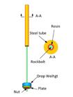
). An end-anchored rockbolt is a kind of grouting bolt whose bolt body is encapsulated in a limited length of the bolt at the distal end of the borehole with resin grout, and the other end is applied tension pretension force by using plate and nut, as shown in Figure 1. In recent decades, the end-anchored rockbolt has been the primary support of roadway in the underground coal mining in China. With the increase of coal mining depth in China, the deep roadway confronts complex conditions such as high ground stress or strong mining disturbing force, which often lead to the occurrence of rock or coal burst (Zhang et al., 2017Zhang, J.F., Jiang, F.X., Yang, J.B., Bai, W.S., Zhang, L. (2017). Rockburst mechanism in soft coal seam within deep coal mines. International Journal of Mining Science and Technology, 27(03): 551-556. https://doi.org/10.1016/j.ijmst.2017.03.011
https://doi.org/10.1016/j.ijmst.2017.03....
; Guo et al., 2017Guo, W.Y., Zhao, T.B., Tan, Y.L., Yu, F.H., Hu, S.C., Yang, F.Q. (2017). Progressive mitigation method of rock bursts under complicated geological conditions. International Journal of Rock Mechanics and Mining Sciences, 96: 11-22. https://doi.org/10.1016/j.ijrmms.2017.04.011
https://doi.org/10.1016/j.ijrmms.2017.04...
; Wen et al., 2019Wen, J.L., Li, H.S., Jiang, F.X., Yu, Z.X., Ma, H.T., Yang, X.L. (2019). Rock burst risk evaluation based on equivalent surrounding rock strength. International Journal of Mining Science and Technology, 29(04): 50-55. https://doi.org/10.1016/j.ijmst.2019.06.005
https://doi.org/10.1016/j.ijmst.2019.06....
; and Wang et al., 2020Wang, H.W., Shi, R.M., Deng, D.X., Jiang, Y.D., Wang, G., Gong, W.L. (2020). Characteristic of stress evolution on fault surface and coal bursts mechanism during the extraction of longwall face in Yima mining area, China. Journal of Structural Geology, 136:104071. https://doi.org/10.1016/j.jsg.2020.104071
https://doi.org/10.1016/j.jsg.2020.10407...
). It is worth noting that, a large number of end-anchored rockbolts were broken and ejected when the rock burst happened as shown in Figure 2. This situation will seriously threaten the safety of working men and mechanical equipment in the roadway (Pan et al., 2014Pan, Y.S., Xiao, Y.H., Li, Z.H., Wang, K.X. (2014). Study of tunnel support theory of rockburst in coal mine and its application. Journal of China Coal Society, 39(2): 222-228. (in Chinese) https://doi.org/10.13225/j.cnki.jccs.2013.2015
https://doi.org/10.13225/j.cnki.jccs.201...
; Kang, 2016Kang, H.P. (2016). Sixty years development and prospects of rock bolting technology for underground coal mine roadways in China. Journal of China University of Mining and Technology 45(006):1071-1081. (in Chinese) https://doi.org/doi:10.13247/j.cnki.jcumt.000583
https://doi.org/doi:10.13247/j.cnki.jcum...
; and Wu et al., 2019Wu, Y.Z., Gao, F.Q., Chen, J.Y., He, J. (2019). Experimental study on the performance of rock bolts in coal burst-prone mines. Rock Mechanics and Rock Engineering, 52: 3959-3970. https://doi.org/10.1007/s00603-019-01794-9
https://doi.org/10.1007/s00603-019-01794...
). Therefore, the dynamic response of end-anchored rockbolt under impact loading has become a key research problem of roadway support in underground coal mining (Wu et al., 2019; Sun, 2018Sun, P. (2018). Comprehensive prevention technology of mining rockburst in Yutian coal mine. PhD Thesis, Xi'an University of science and technology. http://cdmd.cnki.com.cn/Article/CDMD-10704-1019916384.htm
http://cdmd.cnki.com.cn/Article/CDMD-107...
).

End-anchored rockbolt (Li, 2017Li, C.C. (2017). Rockbolting Principles and Applications, Butterworth-Heinemann. https://doi.org/10.1016/C2015-0-01742-7
https://doi.org/10.1016/C2015-0-01742-7... ).

Typical rock support failure patterns caused by rock bursts (Wu et al. 2019Wu, Y.Z., Gao, F.Q., Chen, J.Y., He, J. (2019). Experimental study on the performance of rock bolts in coal burst-prone mines. Rock Mechanics and Rock Engineering, 52: 3959-3970. https://doi.org/10.1007/s00603-019-01794-9
https://doi.org/10.1007/s00603-019-01794... and Sun 2018Sun, P. (2018). Comprehensive prevention technology of mining rockburst in Yutian coal mine. PhD Thesis, Xi'an University of science and technology. http://cdmd.cnki.com.cn/Article/CDMD-10704-1019916384.htm
http://cdmd.cnki.com.cn/Article/CDMD-107... ).
How to examine the anti-impact properties on rockbolt support system under impact loading is an important research direction (Tannant et al., 1995Tannant, D.D., Brummer, R.K., Yi, X. (1995). Rockbolt behaviour under dynamic loading: Field tests and modelling. International Journal of Rock Mechanics and Mining sciences & Geomechanics Abstracts, 32(6): 537-550. https://doi.org/10.1016/0148-9062(95)00024-B
https://doi.org/10.1016/0148-9062(95)000...
; Sharifzadeh et al., 2020Sharifzadeh, M., Lou, J., Crompton, B. (2020). Dynamic performance of energy-absorbing rockbolts based on laboratory test results. Part I: Evolution, deformation mechanisms, dynamic performance and classification. Tunnelling and Underground Space Technology, 105: 103510. https://doi.org/10.1016/j.tust.2020.103510
https://doi.org/10.1016/j.tust.2020.1035...
and Vallejos et al., 2020Vallejos, J.A., Marambio, E., Burgos, L., Gonzalez, C.V. (2020). Numerical modelling of the dynamic response of threadbar under laboratory-scale conditions. Tunnelling and Underground Space Technology, 100: 103263. https://doi.org/10.1016/j.tust.2019.103263
https://doi.org/10.1016/j.tust.2019.1032...
). Many testing methods have been studied extensively in laboratory to verify the dynamic performance of rockbolts (Yi and Kaiser, 1994Yi, X., Kaiser, P.K. (1994). Impact testing for rockbolt design in rockburst conditions. International Journal of Rock Mechanics and Mining Sciences & Geomechanics Abstracts, 31(6): 671-685. https://doi.org/10.1016/0148-9062(94)90007-8
https://doi.org/10.1016/0148-9062(94)900...
; Player et al., 2004Player, J.R., Villaescusa, E., Thompson, A.G. (2004). Dynamic testing of rock reinforcement using the momentum transfer concept. Ground support in mining and underground construction, 327-340. https://www.researchgate.net/profile/Ernesto_Villaescusa/publication/269932758_Dynamic_testing_of_rock_reinforcement_using_the_momentum_transfer_concept/links/549a45b90cf2fedbc30cb343.pdf
https://www.researchgate.net/profile/Ern...
and 2009; He et al., 2014He, M., Gong, W., Wang, J., Qi, P., Tao, Z., Du, S., Peng, Y. (2014). Development of a novel energy-absorbing bolt with extraordinarily large elongation and constant resistance. International Journal of Rock Mechanics and Mining Sciences, 67: 29-42. https://doi.org/10.1016/j.ijrmms.2014.01.007
https://doi.org/10.1016/j.ijrmms.2014.01...
; Gong et al., 2018Gong, W.L., Sun, Y.X., Gao, X., He, M.C., Qi, P. (2018). Dynamic characteristics of constant-resistance-large-deformation bolts based on weight-dropping tests. Chinese Journal of Rock Mechanics and Engineering, 37(11): 2498-2509. (in Chinese). https://doi.org/10.13722/j.cnki.jrme.2018.0674
https://doi.org/10.13722/j.cnki.jrme.201...
; and Wang et al., 2018Wang, A.W., Gao, Q.S., Dai, L.P., Pan, Y.S., Zhang, J.Z., Chen, J.Q. (2018). Static and dynamic performance of rebar bolts and its adaptability under impact loading. Journal of China Coal Society, 43(11): 2999-3006. (in Chinese) https://doi.org/10.13225/j.cnki.jccs.2018.8020.
https://doi.org/10.13225/j.cnki.jccs.201...
). The most common dynamic testing facilities are CANMET-MMSL facility in Canada (see Figure 3a) and WASM facility in Australia (see Figure 3b). The experimental testing principle between CANMET-MMSL dynamic test facility and WASM dynamic test facility is markedly different. The CANMET-MMSL testing machine takes advantage of the principle of energy transfer, while WASM testing machine adopt the principle of momentum transfer. As shown in Figure 4, the CANMET-MMSL testing machine converts the potential energy of the drop weight into kinetic energy so that impacts the anchored end of rockbolt in the steel tube and causes deformation and fail. On the other hand, the beam, steel tube, mass block and rockbolt of WASM testing machine begin to fall as a system until the beam is suddenly stopped by the buffers. Then the rockbolt continues fall and could lengthen and damage. Distinctly, the testing principle of energy transfer is more consistent with the in situ conditions.


A large amount of test data provided by the dynamic impact testing facilities is very valuable, which greatly promotes the development of support anchoring technology and the evolution of new rockbolt (Varden et al., 2008Varden, R., Lachenicht, R., Player, J.R., Thompson, A., Villaescusa, E. (2008). Development and implementation of the garford dynamic bolt at the Kanowna Belle Mine. Proceedings of the 10th Underground Operators’ Conference, Launceston, Australia. https://www.researchgate.net/profile/Ernesto_Villaescusa/publication/265008457_Development_and_Implementation_of_the_Garford_Dynamic_Bolt_at_the_Kanowna_Belle_Mine/links/5440f6c60cf2ebb03690d1a3.pdf
https://www.researchgate.net/profile/Ern...
; He et al., 2014He, M., Gong, W., Wang, J., Qi, P., Tao, Z., Du, S., Peng, Y. (2014). Development of a novel energy-absorbing bolt with extraordinarily large elongation and constant resistance. International Journal of Rock Mechanics and Mining Sciences, 67: 29-42. https://doi.org/10.1016/j.ijrmms.2014.01.007
https://doi.org/10.1016/j.ijrmms.2014.01...
; Sharifzadeh et al., 2020Sharifzadeh, M., Lou, J., Crompton, B. (2020). Dynamic performance of energy-absorbing rockbolts based on laboratory test results. Part I: Evolution, deformation mechanisms, dynamic performance and classification. Tunnelling and Underground Space Technology, 105: 103510. https://doi.org/10.1016/j.tust.2020.103510
https://doi.org/10.1016/j.tust.2020.1035...
). Plouffe et al. (2008Plouffe, M., Anderson, T., Judge, K. (2008). Rock bolts testing under dynamic conditions at CANMET-MMSL. Proceedings of the 6th International Symposium on Ground Support in Mining and Civil Engineering Construction, Cape Town, South Africa. http://www.saimm.co.za/Conferences/GroundSupport2008/581-596_Plouffe.pdf
http://www.saimm.co.za/Conferences/Groun...
) carried on the experimental research to the friction type rockbolt with the help of the CANMET-MMSL impact testing machine and verified the energy balance of the test system. Li (2010Li, C.C. (2010). A new energy-absorbing bolt for rock support in high stress rock masses. International Journal of Rock Mechanics and Mining Sciences, 47(3): 396-404. https://doi.org/10.1016/j.ijrmms.2010.01.005
https://doi.org/10.1016/j.ijrmms.2010.01...
) designed the D bolt and the dynamic drop testing showed that the cumulative dynamic energy absorption of the D bolt is measured to be 47 kJ/m. Furthermore, the D bolts were tested at an impact velocity of 5.4-6.2 m/s and with impact energy varying from 10 to 60 kJ by CANMET-MMSL testing machine (Li and Doucet, 2012). Zhao et al. (2020Zhao, X., Zhang, S., Zhu, Q., Li, H., Chen, G., Zhang, P. (2020). Dynamic and static analysis of a kind of novel J energy-releasing bolts. Geomatics, Natural Hazards and Risk, 11(1): 2486-2508. https://doi.org/10.1080/19475705.2020.1833991
https://doi.org/10.1080/19475705.2020.18...
) developed an energy-absorbing rockbolt, called J-bolt, and the drop dynamic impact test (CANMET-MMSL facility) results show that the accumulated energy absorbing capacity reaches 46.5 kJ under impact loading condition. Masoudi and Sharifzadeh (2018Masoudi, R., Sharifzadeh, M. (2018). Reinforcement selection for deep and high-stress tunnels at preliminary design stages using ground demand and support capacity approach. International Journal of Mining Sciences and Technology, 28(4): 573-582. https://doi.org/10.1016/j.ijmst.2018.01.004
https://doi.org/10.1016/j.ijmst.2018.01....
) classified the rockbolts into five groups namely, stiff, medium yielding, high yielding, very high yielding, and extremely high yielding rockbolt according to their energy absorption capacity. However, the laboratory dynamic impact test confronts the problems of long testing period, potential security risk and high testing cost. The development of numerical simulation technology has improved this situation about dynamic performance research of rockbolt very well. In recent years, various efforts have been made to numerically modelling the dynamic behaviour of different rockbolts. Mortazavi and Alavi (2013Mortazavi, A., Alavi, F.T. (2013). A numerical study of the behavior of fully grouted rockbolts under dynamic loading. Soil Dynamics and Earthquake Engineering, 54: 66-72. https://doi.org/10.1016/j.soildyn.2013.08.003
https://doi.org/10.1016/j.soildyn.2013.0...
) studied the mechanical performance of fully grouted bolt under dynamic loading condition using FLAC3D and considered that the yield bolt has a better performance on absorbing dynamic stress wave. He et al. (2017) investigated the numerical simulation of He bolt using LS-DYNA software and verified the dynamic experimental results. Vallejos et al. (2020Vallejos, J.A., Marambio, E., Burgos, L., Gonzalez, C.V. (2020). Numerical modelling of the dynamic response of threadbar under laboratory-scale conditions. Tunnelling and Underground Space Technology, 100: 103263. https://doi.org/10.1016/j.tust.2019.103263
https://doi.org/10.1016/j.tust.2019.1032...
) developed a numerical model to evaluate the dynamic response of threadbar and found that the dissipated energy and the axial displacement of threadbar followed a linear trend. Differently from the other rockbolts described above, the end-anchored rockbolt absorbs kinetic energy and fracture energy of rock mass by its free bolt body deformation. The dynamic response of end-anchored rockbolt has not been fully interpreted, especially considering the influence of grouted length, bolt diameter and bolt material.
In this study, a numerical modelling of dynamic impact test on end-anchored bolt is developed based on CANMET-MMSL facility testing principle. The numerical study focuses on the dynamic response of end-anchored bolt, which is widely used as rock reinforcement in China underground coal mining. The dynamic performance of end-anchored rockbolt is analyzed under different impact energy levels and the effects of anchoring length, bolt diameter and bolt material are discussed in detail.
2 NUMERICAL MODELLING
2.1 Geometric model
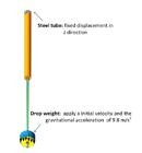
The finite element model of dynamic impact test on rockbolt is established in ABAQUS by using the drop test method, as shown in Figure 5. Nut and plate are installed at the free end of the bolt, the other end of bolt is installed in the hollow steel tube by resin. The detailed dimensions of each component of the model are listed in table 1. The main function of the drop weight is to provide the source of impact energy. Each component of the model is meshed finely, and the cell type is set to C3D8R (8-junction linear hexahedron element, reduction integral, hourglass control).
2.2 Model Material and Boundary Conditions
In numerical simulation, the material parameters commonly determines whether the simulation results are correct. As known that, the yield strength and tensile strength of steel material will change under dynamic loading condition. The dynamic parameters of steel material can be estimated by means of elastic properties and scaled by dynamic strengthening coefficient DIF (Malvar and Crawford, 1998Malvar, L.J., Crawford, J.E. (1998). Dynamic increase factors for steel reinforcing bars. In:28th DDESB Seminar. Orlando, USA. https://www.researchgate.net/publication/235099732_Dynamic_Increase_Factors_for_Steel_Reinforcing_Bars/download
https://www.researchgate.net/publication...
):
The DIF is the dynamic strengthening coefficient, the is the strain rate, the f y is the static yield limit of steel (unit MPa); and are the yield limit and tensile strength coefficient of steel, respectively. Malvar and Crawford (1998Malvar, L.J., Crawford, J.E. (1998). Dynamic increase factors for steel reinforcing bars. In:28th DDESB Seminar. Orlando, USA. https://www.researchgate.net/publication/235099732_Dynamic_Increase_Factors_for_Steel_Reinforcing_Bars/download
https://www.researchgate.net/publication...
) suggested that DIF was applied for steel with static yield loads of 290 MPa to 710 MPa and strain rates of 10-4s-1 to 225s-1. Li et al. (2019Li, L., Hagan, P., Saydam, S., Hebblewhite, B., Zhang, C. (2019). A laboratory study of shear behaviour of rockbolts under dynamic loading based on the drop test using a double shear system. Rock Mechanics and Rock Engineering, 52: 3413-3429. https://doi.org/10.1007/s00603-019-01776-x
https://doi.org/10.1007/s00603-019-01776...
) and St-Pierre (2007St-Pierre, L. (2007). Development and validation of a dynamic model for a cone bolt anchoring system. Master thesis. McGill University. https://central.bac-lac.gc.ca/.item?id=MR48253&op=pdf&app=Library&oclc_number=710884980
https://central.bac-lac.gc.ca/.item?id=M...
) applied DIF to estimate the experimental results. Vallejos et al. (2020Vallejos, J.A., Marambio, E., Burgos, L., Gonzalez, C.V. (2020). Numerical modelling of the dynamic response of threadbar under laboratory-scale conditions. Tunnelling and Underground Space Technology, 100: 103263. https://doi.org/10.1016/j.tust.2019.103263
https://doi.org/10.1016/j.tust.2019.1032...
) used the DIF coefficient to determine the material dynamic parameters and the results showed that the DIF could effectively describe the change of steel properties under dynamic loading condition.
A damage variable D is introduced to accurately describe the damage of rockbolt, and the damage evolution law is represented by the stiffness degradation of the material. A scalar damage variable D i is used to represent the stiffness degradation associated with each effective failure mechanism. The stress tensor of steel material is calculated by the scalar damage equation in the process of analysis, that was:
Where, D is the total damage variable; is the effective stress tensor calculated in the current increment. As the equivalent plastic strain increased, the damage of bolt increases gradually. When D=1, the material loses its bearing capacity and the bolt failed.
A ductile damage model is used to simulate the constitutive behaviour of rockbolt. It is assumed that the equivalent plastic strain is a function of stress triaxiality and strain rate when the damage occurred, that is:
The is equivalent plastic strain rate, the is stress triaxiality, the p is compressive stress, and the q is Mises equivalent stress.
The damage variable increases monotonously with plastic deformation according to:
The rockbolt material is made of BHRB500 steel, which is widely used in China. The mechanical parameters of the material are shown in Table 2, and the stress-strain curve is shown in Figure 6. In order to focus more on the study of impact energy absorption effect of bolt body, the constitutive relations of other components are simplified. The drop weight is simplified to the rigid body model, and the steel tube, plate, nut and resin grout are simplified to the elastic model. The mechanical parameters are listed in Table 3.

Figure 7 shows the boundary conditions of the model. The bottom of the steel tube is set as the displacement completely fixed boundary condition. The gravity acceleration of drop weight is set as 9.8 m/s2 in Z direction. Other boundaries are free boundary conditions in this model. The contact interface between nut and bolt is set as binding constraint, and other contact interfaces are set as hard contact and frictionless. The contact interface between resin and rockbolt is set as bond-friction model. The normal bond stiffness is 20 GPa, the tangential bond stiffness is 20 GPa, the bond strength is 200 MPa, and the friction coefficient is 0.3. The initial impact velocity in Z direction of drop weight is applied according to the impact energy level. The calculation is obtained by kinetic energy equation E k =0.5mv 2.
2.3 Model Calibration
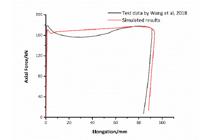
To determine the accuracy of the numerical model, a dynamic impact test on end-anchored rockbolt was simulated referring to the test data from paper of Wang et al. (2018Wang, A.W., Gao, Q.S., Dai, L.P., Pan, Y.S., Zhang, J.Z., Chen, J.Q. (2018). Static and dynamic performance of rebar bolts and its adaptability under impact loading. Journal of China Coal Society, 43(11): 2999-3006. (in Chinese) https://doi.org/10.13225/j.cnki.jccs.2018.8020.
https://doi.org/10.13225/j.cnki.jccs.201...
). The simulation parameters are shown in Table 4, and the simulation results are shown in Figure 8. By calibrating the bond stiffness and strength of bolt and resin, the simulated load-elongation curve is similar to that of laboratory test data. The mass of the drop weight is defined as 1000 kg and the initial velocity of drop weight is set as 6.325 m/s. It is demonstrated that the present numerical model could excellently reflect the dynamic mechanical behaviour of end-anchored rockbolt under impact loading.
2.4 Simulation plan
The inertia effect of drop weight in dynamic impact testing cannot be ignored and the dynamic behaviour of structure material are both velocity and mass sensitive (Karagiozova et al. 2000Karagiozova, D., Alves M., Jones, Norman. (2000). Inertia effects in axisymmetrically deformed cylindrical shells under axial impact. International Journal of Impact Engineering, 24(10): 1083-1115. https://doi.org/10.1016/S0734-743X(00)00028-2
https://doi.org/10.1016/S0734-743X(00)00...
). However, refer to the previous dynamic impact testing of rockbolts (Player et al., 2008Player, J.R., Thompson, A.G., Villaescusa, E. (2008). Dynamic testing of reinforcement systems. In 6th International Symposium on Ground Support in Mining and Civil Engineering Construction, 597-622. http://saimm.org.za/Conferences/GroundSupport2008/597-622_Player.pdf
http://saimm.org.za/Conferences/GroundSu...
; He et al., 2014He, M., Gong, W., Wang, J., Qi, P., Tao, Z., Du, S., Peng, Y. (2014). Development of a novel energy-absorbing bolt with extraordinarily large elongation and constant resistance. International Journal of Rock Mechanics and Mining Sciences, 67: 29-42. https://doi.org/10.1016/j.ijrmms.2014.01.007
https://doi.org/10.1016/j.ijrmms.2014.01...
; and Vallejos et al., 2020Vallejos, J.A., Marambio, E., Burgos, L., Gonzalez, C.V. (2020). Numerical modelling of the dynamic response of threadbar under laboratory-scale conditions. Tunnelling and Underground Space Technology, 100: 103263. https://doi.org/10.1016/j.tust.2019.103263
https://doi.org/10.1016/j.tust.2019.1032...
), the mass of the drop weight is generally constant, and the impact energy can be determined by changing the drop height, that is, the initial velocity of the drop weight. Therefore, the mass of the drop weight is fixed as 1000 kg in this paper. In order to study the influence of different parameters on the dynamic performance of end-anchored rockbolt, the following simulation scheme is designed as follows.
-
(i) According to the formula E k =0.5mv 2, the initial velocity of the drop weight is adjusted when the impact energy is 5kJ, 10kJ, 15kJ and 20kJ, respectively. The simulation scheme under different impact energy conditions is listed in Table 5.
-
(ii) Under impact energy of 15kJ, the anchored length of rockbolts is set as 0.5 m, 1.0 m, 1.5 m, and 2.0 m, respectively.
-
(iii) Under impact energy of 15kJ, the diameter of rockbolts is set as 18, 20 and 22 mm, respectively.
-
(iv) The models with different steel materials are simulated under impact energy of 15kJ. The steel materials are listed in Table 6.
3 DYNAMIC IMPACT SIMULATION RESULTS AND DISCUSSIONS
3.1 Dynamic response of rockbolt under impact energy of 15kJ
The dynamic impact model of the end-anchored rockbolt is calculated in ABAQUS/Explicit. Under the impact energy of 15kJ, the impact force of plate and the axial displacement of bolt are shown in Figure 9. It can be seen from Figure 9 that the peak impact force is 297kN, the dynamic response time is 31ms, and the impact force changes greatly at the moment of impact. After about 1ms, the force tends to stabilize and the impact force after stability is 170kN, which is 57.2% of the peak force. At the same time, the elongation of the bolt increases the fastest at the impact moment. As the impact kinetic energy is absorbed by the rockbolt, the elongation rate of the bolt slows down. After the elongation reaches the peak value of 91.1mm, it falls back to 86.1mm due to elastic deformation.

The axial stress and shear stress of the anchoring section of rockbolt during the impact are shown in Figure 10. It can be seen that the stress characteristics of the anchoring section of the bolt can be divided into three stages with the impact time. In the initial stage of impact, the axial stress peak and shear stress peak of the anchoring section are concentrated on the impacted side, and the values decreases from the maximum value to zero exponentially. In the middle stage of the impact, the bond between bolt and resin fails from the impacted side, and the peak values of the axial stress and shear stress move to the end of the rockbolt along with the failure point of the anchoring bond. As the kinetic energy is absorbed by the rockbolt continuously, the axial stress and the shear stress continue decrease and the shear stress rapidly drops to zero in a sawtooth shape. At the final of the impact, the peak value no longer moves backward when the axial stress is insufficient to make the anchoring bond failure, and the axial stress and shear stress gradually decrease to zero.
3.2 Dynamic response of rockbolt with different impact energy
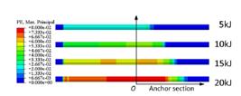
Based on the simulation in Section 3.1, the initial kinetic energy was adjusted by changing the initial velocity of the drop weight. The dynamic impact test simulation of the end-anchored bolt with energy levels of 5, 10, and 20kJ was performed respectively. The mechanical response of the rockbolt under different energy impacts is shown in Table 7 and Figure 11. With the increase of impact energy, the elongation of the rockbolt increases rapidly from 27.588 mm to 155.324 mm, the maximum plastic strain increases from 0.028 to 0.085, and the interface debonding length between bolt and resin increases from 520 mm to 980 mm. However, the maximum axial force of the rockbolt increases less.


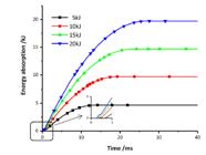
Figure 12 is the curves of maximum axial force and elongation of rockbolt under different impact energies. As the impact energy increases, the impact dynamic response time of rock bolt increases from 20ms to 33ms, and the maximum axial force does not change significantly. But under high impact energy, the rockbolt needs a longer response time to absorb energy. For every 5kJ increase in impact energy, the extension of the rockbolt increases by about 30 mm. The change curves of the energy absorbed by end-anchored rockbolt with time under different impact energy is shown in Figure 13. The rockbolt absorbs most of the impact energy under the impact of each energy level, and a small part of the energy is stored in the system in the form of elastic strain energy and kinetic energy. With the energy level increases, the rate at which the bolt absorbs energy increases significantly. The impact energy is mainly dissipated by the plastic deformation of the free section and the debonding section of end-anchored rockbolt. The length of the plastic energy-absorbing section and the maximum plastic strain of the bolt gradually increase with the impact load increases, as shown in Figure 14. In the design of roadway support in coal mines of China, the anchoring length of the end-anchored rockbolt is usually designed to be about 1/3 of the total length. The interface between bolt and resin will fail and debond under the impact loading condition, and the debonding length increases with the increase of impact energy. Therefore, the end-anchored rockbolt needs a larger anchoring length to ensure its effectivity under dynamic impact load.

3.3 Effect of anchoring length
The dynamic response of the end-anchored rockbolt under different anchoring length conditions is listed in Table 8. When the anchoring length is 0.5m, the bolt is pulled out abruptly, but when the anchoring length is 1m and 1.5m, the rockbolts only debond. Conspicuously, the rockbolt breaks at the free section when the anchoring length is 2m, as shown in Figure 15. Figure 16 shows the curves of axial force and elongation of rockbolt under different anchoring lengths. With the lengthening of the anchoring section, the axial force and elongation of the bolt increase slightly, and the maximum plastic strain increases greatly. The end-anchored rockbolt absorbs impact energy through the deformation of the free section of bolt. When the anchor section is too long, the bolt does not have enough free section to absorb the impact energy. The rockbolt breaks when the energy absorbed by the free section per unit length exceeds a certain critical value. If the anchoring section is too short, the anchoring interface lacks sufficient friction and will fail to debond. It can be seen from Figure 17 that the anchoring length has no effect on the energy absorption rate of rockbolt. When the anchoring length is 1m, the impact energy absorbed by rock bolt is the same as that when the anchoring length is 1.5m.


From Figure 18, the plastic deformation of the rockbolt, which absorbs impact energy, appears in the free section and the debonding section. The average plastic strain of rockbolt with shorter anchoring part is smaller. When the rockbolt is subjected to an impact loading, the free section can play a buffer role through its elastic deformation. In other words, the energy absorption performance of end-anchored rockbolt will be much improved if the impact energy can be dispersed on the free section of bolt.

3.4 Effect of bolt diameter
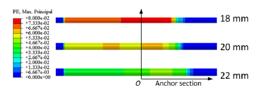
The dynamic impact test simulation is carried out on three different end-anchored rockbolts with the bolt diameters of 18mm, 20mm and 22mm, respectively. As listed in Table 9, the end-anchored rockbolt with 22mm diameter is pulled out under the impact energy of 15kJ, and the anchor section of rockbolt with 18mm and 20mm diameter debonds. As plotted in Figure 19, when the diameter of the bolt increases by 2mm, the axial force of the bolt increases by about 33kN, the elongation of the bolt decreases by about 20mm, and the maximum plastic strain decreases by about 0.013.
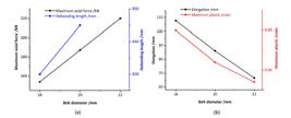
Figure 20 shows curves of maximum axial force and elongation of rockbolt under different bolt diameters. Under impact loading, the rockbolt with larger diameter has a greater axial force, smaller elongation and shorter dynamic response time, which is more likely to cause failure of the bolt-resin interface. This is the main reason leading to the failure of the rockbolt as a whole. The debonding length of rockbolt with the 22mm diameter exceeds 845mm, and the remaining bonding interface cannot provide sufficient bonding force to resist the impact of the drop weight. This leading to further damage and complete debonding. It can be seen from Figure 21 that rockbolts of different diameters start to yield at the same time, and rockbolts with larger diameters have a higher energy absorption rate.
The energy absorption rate of end-anchored rockbolt is positively correlated with its diameter. A large diameter rockbolt has a higher energy absorption rate but greater axial force, which leads to an increase in the debonding length of the anchor section. If the bolt diameter is too large, the anchor section will debond completely when the energy absorption performance is not fully utilized. The debonding length of the rockbolt with a smaller diameter reduces slightly under the impact loading, but the bolt will occur a greater plastic deformation. In the case of 15kJ impact energy, the maximum plastic strain of the rockbolt with a diameter of 18mm is 25% higher than that of the rockbolt with a diameter of 20mm, as shown in Figure 22.


3.5 Effect of material properties
The wide application of new high-strength and high-toughness steel materials significantly improves the anti-impact performance of the rockbolt in China (Kang, 2016Kang, H.P. (2016). Sixty years development and prospects of rock bolting technology for underground coal mine roadways in China. Journal of China University of Mining and Technology 45(006):1071-1081. (in Chinese) https://doi.org/doi:10.13247/j.cnki.jcumt.000583
https://doi.org/doi:10.13247/j.cnki.jcum...
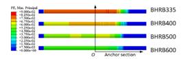
). The influence of material properties on the dynamic performance of end-anchored bolt is studied through dynamic impact test simulation of several commonly steel materials. The numerical results are listed in Table 10 and shown in Figure 23. It can be seen that the maximum axial force of and the debonding length of the anchoring interface are positively related to the yield strength of the bolt material, and the elongation and the maximum plastic strain are negatively related to the strength of the bolt material.
Figure 24 shows the axial force and elongation of rockbolt under different materials. Under the same impact energy, the high-strength anchor has higher axial force, shorter elongation, and shorter dynamic response time. From Figure 25, the energy absorption rate of the rockbolt is proportional to the material strength, and the energy absorption rate of rockbolt with a higher material strength is greater. There is little difference in total absorption energy. Figure 26 shows the plastic strain of rockbolts with different materials under Impact loading condition. The plastic deformation of the rockbolt is inversely proportional to the bolt material strength. The greater the material strength, the smaller the plastic strain. The high strength rockbolt has a longer debonding length, which is related to the higher axial force caused by the steel material. The application of high-strength materials can effectively improve the anti-impact performance of the rockbolt but slightly increase the debonding length of the anchoring interface under impact loading. The strength of the BHRB600 bolt is 20% higher than that of the BHRB500 bolt, which reduces the maximum plastic strain by 17.2% and increases the debonding length by 1.78%.


4 CONCLUSIONS
In this paper, a numerical model for dynamic impact testing of end-anchored rockbolt is established and the mechanical response of rockbolt under dynamic impact loading condition is simulated. Despite some variables and parameters are not taken into consideration, the numerical results are consistent with the laboratory dynamic test data. Further research with emphasis on the constitutive behaviour of end-anchored rockbolt under dynamic loading conditions are required. The following conclusions can be made from the preceding results:
-
(1) The stress characteristics of the anchoring section of the end-anchored rockbolt can be divided into three stages with the impact time. In the initial stage of impact, the axial stress and shear stress of the anchoring section decrease from the maximum value to zero exponentially. In the middle stage of impact, the axial stress and the shear stress continue decrease and the shear stress rapidly drops to zero in a sawtooth shape. At the final stage of impact, the stress peak values no longer move backward, and the stresses gradually decrease to zero.
-
(2) The impact dynamic response time of rockbolt increases, and the maximum axial force does not change significantly with the increase of impact energy. The elongation of the rockbolt increases by about 30 mm for every 5kJ increase in impact energy. When the impact energy level increases, the energy absorption rate and maximum plastic strain both increase significantly.
-
(3) The impact energy is mainly dissipated by the plastic deformation of free section and debonding section of end-anchored rockbolt. If the free section is too short, the absorbed impact energy will exceed the critical value and cause the bolt fracture. If the free section is too long, the anchoring section bolt will be pulled out suddenly. As a result, the free section plays a buffer role through its elastic deformation when the rockbolt is subjected to an impact loading.
-
(4) The maximum axial force of end-anchored rockbolt is proportional to the bolt diameter and material strength, and the anchoring length is also proportional to them. However, the plastic deformation of end-anchored rockbolt is inversely proportional to the bolt diameter and material strength, and the elongation is also inversely proportional to them. It is remarkable that the energy absorption rate and anti-impact performance of the end-anchored rockbolt can be improved by increasing the bolt diameter and the bolt material strength.
Acknowledgment
This work has been supported by the Major Program of Shandong Provincial Natural Science Foundation (ZR2019ZD13), Major Scientific and Technological Innovation Project of Shandong Provincial Key Research Development Program (2019SDZY02), Shandong Provincial Natural Science Foundation (ZR2020QE122) and Scientific Research Foundation of Shandong University of Science and Technology for Recruited Talents.
References
- Gong, W.L., Sun, Y.X., Gao, X., He, M.C., Qi, P. (2018). Dynamic characteristics of constant-resistance-large-deformation bolts based on weight-dropping tests. Chinese Journal of Rock Mechanics and Engineering, 37(11): 2498-2509. (in Chinese). https://doi.org/10.13722/j.cnki.jrme.2018.0674
» https://doi.org/10.13722/j.cnki.jrme.2018.0674 - Guo, W.Y., Zhao, T.B., Tan, Y.L., Yu, F.H., Hu, S.C., Yang, F.Q. (2017). Progressive mitigation method of rock bursts under complicated geological conditions. International Journal of Rock Mechanics and Mining Sciences, 96: 11-22. https://doi.org/10.1016/j.ijrmms.2017.04.011
» https://doi.org/10.1016/j.ijrmms.2017.04.011 - He, M., Gong, W., Wang, J., Qi, P., Tao, Z., Du, S., Peng, Y. (2014). Development of a novel energy-absorbing bolt with extraordinarily large elongation and constant resistance. International Journal of Rock Mechanics and Mining Sciences, 67: 29-42. https://doi.org/10.1016/j.ijrmms.2014.01.007
» https://doi.org/10.1016/j.ijrmms.2014.01.007 - He, M., Li, C., Gong, W., Sousa, L.R., Li, S. (2017). Dynamic tests for a Constant-Resistance-Large-Deformation bolt using a modified SHTB system. Tunnelling and Underground Space Technology, 64: 103-116. https://doi.org/10.1016/j.tust.2016.12.007
» https://doi.org/10.1016/j.tust.2016.12.007 - Karagiozova, D., Alves M., Jones, Norman. (2000). Inertia effects in axisymmetrically deformed cylindrical shells under axial impact. International Journal of Impact Engineering, 24(10): 1083-1115. https://doi.org/10.1016/S0734-743X(00)00028-2
» https://doi.org/10.1016/S0734-743X(00)00028-2 - Kang, H.P. (2016). Sixty years development and prospects of rock bolting technology for underground coal mine roadways in China. Journal of China University of Mining and Technology 45(006):1071-1081. (in Chinese) https://doi.org/doi:10.13247/j.cnki.jcumt.000583
» https://doi.org/doi:10.13247/j.cnki.jcumt.000583 - Li, C.C. (2017). Rockbolting Principles and Applications, Butterworth-Heinemann. https://doi.org/10.1016/C2015-0-01742-7
» https://doi.org/10.1016/C2015-0-01742-7 - Li, C.C. (2010). A new energy-absorbing bolt for rock support in high stress rock masses. International Journal of Rock Mechanics and Mining Sciences, 47(3): 396-404. https://doi.org/10.1016/j.ijrmms.2010.01.005
» https://doi.org/10.1016/j.ijrmms.2010.01.005 - Li, C.C.; Doucet, C. (2012). Performance of D-Bolts Under Dynamic Loading. Rock Mechanics and Rock Engineering, 45(2): 193-204. https://doi.org/10.1007/s00603-011-0202-1
» https://doi.org/10.1007/s00603-011-0202-1 - Li, L., Hagan, P., Saydam, S., Hebblewhite, B., Zhang, C. (2019). A laboratory study of shear behaviour of rockbolts under dynamic loading based on the drop test using a double shear system. Rock Mechanics and Rock Engineering, 52: 3413-3429. https://doi.org/10.1007/s00603-019-01776-x
» https://doi.org/10.1007/s00603-019-01776-x - Malvar, L.J., Crawford, J.E. (1998). Dynamic increase factors for steel reinforcing bars. In:28th DDESB Seminar. Orlando, USA. https://www.researchgate.net/publication/235099732_Dynamic_Increase_Factors_for_Steel_Reinforcing_Bars/download
» https://www.researchgate.net/publication/235099732_Dynamic_Increase_Factors_for_Steel_Reinforcing_Bars/download - Masoudi, R., Sharifzadeh, M. (2018). Reinforcement selection for deep and high-stress tunnels at preliminary design stages using ground demand and support capacity approach. International Journal of Mining Sciences and Technology, 28(4): 573-582. https://doi.org/10.1016/j.ijmst.2018.01.004
» https://doi.org/10.1016/j.ijmst.2018.01.004 - Mortazavi, A., Alavi, F.T. (2013). A numerical study of the behavior of fully grouted rockbolts under dynamic loading. Soil Dynamics and Earthquake Engineering, 54: 66-72. https://doi.org/10.1016/j.soildyn.2013.08.003
» https://doi.org/10.1016/j.soildyn.2013.08.003 - Pan, Y.S., Xiao, Y.H., Li, Z.H., Wang, K.X. (2014). Study of tunnel support theory of rockburst in coal mine and its application. Journal of China Coal Society, 39(2): 222-228. (in Chinese) https://doi.org/10.13225/j.cnki.jccs.2013.2015
» https://doi.org/10.13225/j.cnki.jccs.2013.2015 - Player, J.R., Villaescusa, E., Thompson, A.G. (2004). Dynamic testing of rock reinforcement using the momentum transfer concept. Ground support in mining and underground construction, 327-340. https://www.researchgate.net/profile/Ernesto_Villaescusa/publication/269932758_Dynamic_testing_of_rock_reinforcement_using_the_momentum_transfer_concept/links/549a45b90cf2fedbc30cb343.pdf
» https://www.researchgate.net/profile/Ernesto_Villaescusa/publication/269932758_Dynamic_testing_of_rock_reinforcement_using_the_momentum_transfer_concept/links/549a45b90cf2fedbc30cb343.pdf - Player, J.R., Thompson, A.G., Villaescusa, E. (2008). Dynamic testing of reinforcement systems. In 6th International Symposium on Ground Support in Mining and Civil Engineering Construction, 597-622. http://saimm.org.za/Conferences/GroundSupport2008/597-622_Player.pdf
» http://saimm.org.za/Conferences/GroundSupport2008/597-622_Player.pdf - Player, J.R., Villaescusa, E., Thompson, A.G. (2009). Dynamic testing of friction rock stabilizers. Proceedings of the 3rd Canada-US Rock Mechanics Symposium and 20th Canadian Rock Mechanics Symposium, Toronto, Canada. https://geogroup.utoronto.ca/wp-content/uploads/RockEng09/PDF/Session11/4027%20PAPER.pdf
» https://geogroup.utoronto.ca/wp-content/uploads/RockEng09/PDF/Session11/4027%20PAPER.pdf - Plouffe, M., Anderson, T., Judge, K. (2008). Rock bolts testing under dynamic conditions at CANMET-MMSL. Proceedings of the 6th International Symposium on Ground Support in Mining and Civil Engineering Construction, Cape Town, South Africa. http://www.saimm.co.za/Conferences/GroundSupport2008/581-596_Plouffe.pdf
» http://www.saimm.co.za/Conferences/GroundSupport2008/581-596_Plouffe.pdf - Sharifzadeh, M., Lou, J., Crompton, B. (2020). Dynamic performance of energy-absorbing rockbolts based on laboratory test results. Part I: Evolution, deformation mechanisms, dynamic performance and classification. Tunnelling and Underground Space Technology, 105: 103510. https://doi.org/10.1016/j.tust.2020.103510
» https://doi.org/10.1016/j.tust.2020.103510 - St-Pierre, L. (2007). Development and validation of a dynamic model for a cone bolt anchoring system. Master thesis. McGill University. https://central.bac-lac.gc.ca/.item?id=MR48253&op=pdf&app=Library&oclc_number=710884980
» https://central.bac-lac.gc.ca/.item?id=MR48253&op=pdf&app=Library&oclc_number=710884980 - Sun, P. (2018). Comprehensive prevention technology of mining rockburst in Yutian coal mine. PhD Thesis, Xi'an University of science and technology. http://cdmd.cnki.com.cn/Article/CDMD-10704-1019916384.htm
» http://cdmd.cnki.com.cn/Article/CDMD-10704-1019916384.htm - Tannant, D.D., Brummer, R.K., Yi, X. (1995). Rockbolt behaviour under dynamic loading: Field tests and modelling. International Journal of Rock Mechanics and Mining sciences & Geomechanics Abstracts, 32(6): 537-550. https://doi.org/10.1016/0148-9062(95)00024-B
» https://doi.org/10.1016/0148-9062(95)00024-B - Vallejos, J.A., Marambio, E., Burgos, L., Gonzalez, C.V. (2020). Numerical modelling of the dynamic response of threadbar under laboratory-scale conditions. Tunnelling and Underground Space Technology, 100: 103263. https://doi.org/10.1016/j.tust.2019.103263
» https://doi.org/10.1016/j.tust.2019.103263 - Varden, R., Lachenicht, R., Player, J.R., Thompson, A., Villaescusa, E. (2008). Development and implementation of the garford dynamic bolt at the Kanowna Belle Mine. Proceedings of the 10th Underground Operators’ Conference, Launceston, Australia. https://www.researchgate.net/profile/Ernesto_Villaescusa/publication/265008457_Development_and_Implementation_of_the_Garford_Dynamic_Bolt_at_the_Kanowna_Belle_Mine/links/5440f6c60cf2ebb03690d1a3.pdf
» https://www.researchgate.net/profile/Ernesto_Villaescusa/publication/265008457_Development_and_Implementation_of_the_Garford_Dynamic_Bolt_at_the_Kanowna_Belle_Mine/links/5440f6c60cf2ebb03690d1a3.pdf - Wang, A.W., Gao, Q.S., Dai, L.P., Pan, Y.S., Zhang, J.Z., Chen, J.Q. (2018). Static and dynamic performance of rebar bolts and its adaptability under impact loading. Journal of China Coal Society, 43(11): 2999-3006. (in Chinese) https://doi.org/10.13225/j.cnki.jccs.2018.8020.
» https://doi.org/10.13225/j.cnki.jccs.2018.8020. - Wang, H.W., Shi, R.M., Deng, D.X., Jiang, Y.D., Wang, G., Gong, W.L. (2020). Characteristic of stress evolution on fault surface and coal bursts mechanism during the extraction of longwall face in Yima mining area, China. Journal of Structural Geology, 136:104071. https://doi.org/10.1016/j.jsg.2020.104071
» https://doi.org/10.1016/j.jsg.2020.104071 - Wen, J.L., Li, H.S., Jiang, F.X., Yu, Z.X., Ma, H.T., Yang, X.L. (2019). Rock burst risk evaluation based on equivalent surrounding rock strength. International Journal of Mining Science and Technology, 29(04): 50-55. https://doi.org/10.1016/j.ijmst.2019.06.005
» https://doi.org/10.1016/j.ijmst.2019.06.005 - Wu, Y.Z., Gao, F.Q., Chen, J.Y., He, J. (2019). Experimental study on the performance of rock bolts in coal burst-prone mines. Rock Mechanics and Rock Engineering, 52: 3959-3970. https://doi.org/10.1007/s00603-019-01794-9
» https://doi.org/10.1007/s00603-019-01794-9 - Yi, X., Kaiser, P.K. (1994). Impact testing for rockbolt design in rockburst conditions. International Journal of Rock Mechanics and Mining Sciences & Geomechanics Abstracts, 31(6): 671-685. https://doi.org/10.1016/0148-9062(94)90007-8
» https://doi.org/10.1016/0148-9062(94)90007-8 - Zhang, J.F., Jiang, F.X., Yang, J.B., Bai, W.S., Zhang, L. (2017). Rockburst mechanism in soft coal seam within deep coal mines. International Journal of Mining Science and Technology, 27(03): 551-556. https://doi.org/10.1016/j.ijmst.2017.03.011
» https://doi.org/10.1016/j.ijmst.2017.03.011 - Zhao, X., Zhang, S., Zhu, Q., Li, H., Chen, G., Zhang, P. (2020). Dynamic and static analysis of a kind of novel J energy-releasing bolts. Geomatics, Natural Hazards and Risk, 11(1): 2486-2508. https://doi.org/10.1080/19475705.2020.1833991
» https://doi.org/10.1080/19475705.2020.1833991
Edited by
Editor:
Publication Dates
-
Publication in this collection
23 Apr 2021 -
Date of issue
2021
History
-
Received
23 Feb 2021 -
Reviewed
25 Feb 2021 -
Accepted
26 Feb 2021 -
Published
02 Mar 2021


