Abstracts
The main purpose of this paper is to provide a set of demonstration experiments in electrostatics. Emphasis is put in regard to the making of apparatuses in order to have useful self-made devices from common materials; obviously some apparatuses need special mechanical skill as a turning operation. All devices are designed in order to have a set of portable experiments.
demonstration experiments; electrostatics; home-made devices
O objetivo principal deste trabalho é propiciar um conjunto de experimentos demonstrativos em eletrostática. A ênfase de sua montagem é a busca pois aparelhos que possam ser produzidos de materiais comuns e pelo próprio experimentados. Alguns aparelhos requerem algum conhecimento mecânico em seu ajuste e todos são projetados de modo a serem portáteis.
experimentos de demonstração; eletrostática; equipamentos caseiros
DESENVOLVIMENTO EM ENSINO DE FÍSICA
Demonstration experiments in electrostatics: low cost devices
Experimentos de demonstração em eletrostática: equipamentos de baixo custo
Alessio Ganci; Salvatore Ganci1 1 E-mail: museodellascienza.s.ganci@gmail.com.
Studio di Catalogazione e Conservazione Strumenti Scientifici, Casarza Ligure, GE, Italy
ABSTRACT
The main purpose of this paper is to provide a set of demonstration experiments in electrostatics. Emphasis is put in regard to the making of apparatuses in order to have useful self-made devices from common materials; obviously some apparatuses need special mechanical skill as a turning operation. All devices are designed in order to have a set of portable experiments.
Keywords: demonstration experiments, electrostatics, home-made devices.
RESUMO
O objetivo principal deste trabalho é propiciar um conjunto de experimentos demonstrativos em eletrostática. A ênfase de sua montagem é a busca pois aparelhos que possam ser produzidos de materiais comuns e pelo próprio experimentados. Alguns aparelhos requerem algum conhecimento mecˆanico em seu ajuste e todos são projetados de modo a serem portáteis.
Palavras-chave: experimentos de demonstração; eletrostática; equipamentos caseiros.
1. Introduction
The main purpose of this paper is to provide a set of demonstration experiments in electrostatics. A particular emphasis is put in regard to the making of apparatuses in order to have useful self-made devices from common materials; obviously some apparatus need special mechanical skill as a turning operation. All devices are designed in order to have a set of portable experiments; Author followed the basic philosophy and the tradition of practical physics, as in a celebrated book of the XIX century [1].
2. Basic self made apparatuses
The basic apparatuses for a meaningful set of experiments in electrostatics are:
a) generators of charge; spherical insulated conductors; b) Plexiglas rods, PVC conduits for electrical installations, pith (the best light conductor material), very thin fishing line;
c) electroscope.
2.1. Generators of charge
Without an electrostatic machine, some experiments are easily performed with low cost generators of charge. A first source of charge (positive or negative) is a common piezoelectric lighter [2] slightly modified as shown
in Fig. 1. Usually, by pressing the handle, a positive charge is obtained; releasing the handle after touching the ground, a negative charge is obtained. Another generator of charge is a cylindrical version of the Volta's Electrophorus developed through beautiful ideas of D.S. Ainslie [3-5]. Our practical realization is shown in Fig. 2. The apparatus works as a common electrophorus and gives a positive charge being negative the charge on PVC conduit. Our version is developed as portable instrument, but it is obvious that a longer device will give a greater amount of charge. With metal rod (a brass or aluminum tube) an electroscope may be charged by direct contact (or, obviously, by induction). You may charge the can electroscopes by conduction several times in succession.
A third source of charge very useful and inexpensive was purchased in Internet and named "Fun Fly Stick". It is a handle little Van De Graaf generator. If this generator is joint to a stainless hollowed sphere having 100 mm in diameter, a voltage of about 50 kV is reached and beautiful but not dangerous sparks happen between the sphere and your knuckles. Figure 3 shows the sphere assembled on a Plexiglas bar and a "Fun Fly Stick" at work.
2.2. Plexiglas rods, PVC conduits for electrical installations
There are available in electrical stores or in plastic materials stores. Are the basic common materials used for experiments described. Pith (the best light conductor material) you can find in the "nature" cutting a branch of elder and extracting the pith. A patient cutting with a razor blade gives us small spheres useful in experiments of electrostatics.
In hobby stores you can find metal bars and various components of interest in order to realize portable devices.
2.3. Electroscopes
2.3.1. Classical electroscope
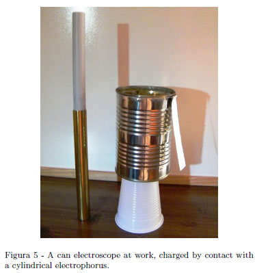
Figure 4 shows the classical home-made "gold leaf type" electroscope. The leaf is an aluminum rigid strip, the end of the strip is U shaped and hanged to a thin bridge soldered on a brass base. The bridge was made using 0.5 mm diameter brass circular wire; use the pliers to bend at right angles the extremities of the bridge. Two small holes in the brass base make assembly easier. Electroscope in Fig. 4 works very well but requires some care in its practical realization. Figure 5 shows a can electroscope. It is a metal can and an aluminum strip simply hanging from the rim. As in the previous case, a bridge made using 0.5 mm diameter brass circular wire allows one more stability to the aluminum strip. Two small holes in the can and tin soldering make assembly functional. A light aluminum strip is U shaped and hangs from this bridge. A Styrofoam cup and double sided tape make the electroscope well insulating and stable. This can electroscope suggested in a Colin Siddons booklet [6] has various advantages, as it will be shown in the next section. It is suggested the realization of a pair of these electroscopes.
2.3.2. Electronic electroscopes
Our electronic electroscope [7]discriminates the sign of the charge very quickly and its sensitivity is high, if it is well constructed. From pedagogical point of view, its use can be an element of confusion for the student. Preliminarily student must be convinced that this device is only a useful tool in order to perform experiments in electrostatics quickly and that the same purpose can be achieved with an ordinary electroscope, used as described in the next section: a "black box" of electronics well working for our electrostatics purposes.
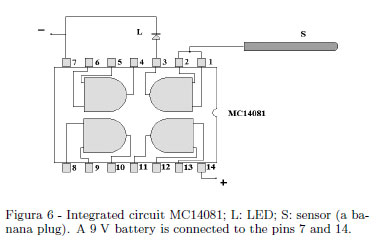
A very sensitive electroscope able to discriminate the sign of an electric charge is a device very useful in electrostatics for a quickly demonstration of electric charges and the sign of the charges (i.e. it is easily demonstrated the opposite signs of the induced charges on dissectible conductors and so on). The very high input impedance of a CMOS semiconductors and their sensitivity to the electric field may be used to this purpose. A simple solution uses one of the gates of a quadrupole dual input MC14081 AND gate as shown in Fig. 6. Only one of the gates is employed: the light emitting diode (LED) is lighted when a positive charged body is brought near S and the LED switches off when a positive charged body is removed. The LED switches on when a negative charged body is removed away and switch off when a negative charged body is brought near S (a banana plug) in Fig. 6 showing the simple schematics.
Figure 7 shows a possible practical solution. The sensitivity of this device is depending on the electric insulation of the electronic board where circuitry is assembled. An external assembling on a Plexiglas sheet (as suggested in Fig. 7) allows one to dry this device with a hair dryer before the use.
Recently, Author has found that some "electronic phase detectors" for non contact a. c. test, acts as the device here described. One of these devices in shown in Fig. 8. All happens as in the electronic electroscope above described LED's lighting happens with the same feature.
Finally, Fig 9 shows a set of brass spheres having diameters in the width 15-30 mm. Except from 20 mm aluminum sphere made by Phywe, all other components are home-made from metal pommels (brass or aluminum) cutting a part of the manufact and adapting to the Plexiglas bar. Couples of equal spheres are useful for some demonstration experiments. Insulating handle are in Plexiglas bar (diameters 5 mm and 8 mm).
3. Phenomenology of the electrified matter: simple experiments
The term "electricity" is etymologically from the Greek " η λ ε κ τ ρ ο ν" (amber), because of the observed attraction of straw by amber rubbed. This "simple" (sometimes considered trivial) phenomenological effect will be discussed at the end of this section.
3.1. Experiment 1. Two electric charges
Between charges having same sign there is repulsion, while between charge of opposite sign there is attraction. A home-made apparatus suitable as "portable experiment" is made adapting a 0.5 m PVC electrical conduit, making two bores: a 5-8 mm bore on its centre on a single wall and a 2 mm bore on the opposite wall as shown in Fig. 10. In this last bore, insert and glue a spring snap button. Figure 10 shows schematically the manufacturing while Fig. 11 shows a concrete solution. This PVC pipe should be in equilibrium when snap spring button is pivoted by a needle or a long metal point, as shown in Fig. 10. For instance, a good material for rubbing is a common "electrostatic" duster, but a rod can be electrified rubbing by own dry hand.
It is easily shown that the PVC pipe rubbed with the same duster gives a repulsive interaction, while Nylon and glass give an attractive interaction.
A critical observation. The sign of the electric charge is determined by the material used and by the cloth used to rubbing. A Plexiglas rod is negatively charged when it is rubbed on Authors's old cat Giulio, while the same Perspex rod is negatively charged on a wool cloth.
You may show qualitatively that the duster has a charge opposite to the charge of the rod rubbed showing the interaction with pivoted PVC pipe.
In an old textbook [8] is emphasized an "anomaly" of the glass. A glass rubbed with wool assumes a positive charge, but the same ground glass rubbed with wool will show a (faint) negative charge. Puzzle your students asking an explication of this "strange" phenomenology, very easy to show.
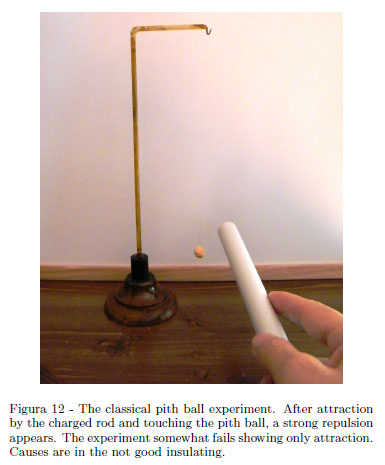
The classical experiment of the pith ball fastened to silk thread (see Fig. 12) can introduce some element of confusion if the experiment is accomplished without a bit of care. It happens a simple attraction by the rod if the wire is not well insulating (air moisture) and/or the ball is not a good conductor. Laboratory practice shows how the old pith ball works better than Styrofoam balls painted with graphite paint. Our apparatus is homemade following ancient style. A glass rod is bent using a little gas torch and forming the hook- shaped end. Dry accurately and warm uniformly the glass; the glass is submerged in a shellac varnish having a little amount of colophon and then dried. As wire, nowadays a very thin fishing wire works well providing a polishing with an Ethyl alcohol when touched by fingers. Experiment still demonstrates the repulsive interaction of charges having same sign. When the experiment fails a discussion with your students ever gives interesting hints of good physics. Ask your students to explain why the pith ball is first attracted to charged rod and then rejected. Why happens only attraction if there are moisture or insulating defects in this simple system?
Assuming positive the charge appearing on the glass rubbed with wool and negative the charge appearing on rubber rubbed with wool, the charge can be discriminated using an ordinary electroscope or an electronic electroscope. The most delicate point is the use of an electronic electroscope able to discriminate the sign of an electric charge. This electroscope was described in the Sect. 2. During his teaching activity, one of us showed preliminarily a comparison between the ordinary gold leaf electroscope and the electronic electroscope. In particular it was shown how an ordinary gold leaf electroscope can discriminate the sign of an electric charge. The classical procedure is the following: bring a charged object near the electroscope, and the superior part is charged with opposite sign by induction, and the lower part holding gold leaf is charged with the same sign of the inductor object. Touch the sphere and neutralize the upper charge. Bring now the charged object near the sphere: if the gold leaf diverges the sign is the same of the inductor object, while if the gold leaf tends to converge the sign is opposite. Figure 13 shows what here described.
Preliminarily, ask your students why an electroscope diverges only bringing a charge object without touching it. It is a good matter to introduce the concept of induction. It is pedagogically useful to show how an
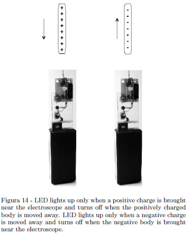
electroscope can be charged by induction. What above described about the sign discrimination using an ordinary electroscope, is pedagogically useful. Our electronic electroscope discriminates the sign of the charge very quickly and its sensitivity is high if well constructed (see Sect. 2). From pedagogical point of view, its use can be an element of confusion for the student. Preliminarily, the student must be convinced that this device is only a useful tool to perform experiments in electrostatics quickly and that the same purpose can be achieved with an ordinary electroscope used as described above: a "black box" of electronics well working for our electrostatics purposes. In the following Figure 14 it is shown again how the electronic electroscope works.
3.2. Experiment 2. Demonstration of Coulomb's law
Do you remember the old P.S.S.C. film entitled "Coulomb's law"? Here, a sensible mechanical balance was used to verify Coulomb's law. The use of a sensible electronic balance is suggested [9] to verify this fundamental law. You need an electronic balance having a resolution 0.01 g or better 0.001 g, three metalized Christmas-tree balls each about 6 cm in diameter, three Plexiglas tubes and adequate supports. The philosophy of the measure is simple:
a) to show that the electric force is directly proportional to the charge;
b) to show that the electric force is inversely proportional to the square of the distance.
Authors were not able to find convincing results using similar devices and we remain in admiration of the excellent results obtained in Ref (9).
3.3. Experiment 3. There are materials called "insulating" or dielectric and materials called "conductors"
This concept is nowadays acquired. Everyone knows the insulation of some devices used in electricity. An experiment in electrostatics can be made using two cans electroscopes. Connect electroscopes with a fishing line using alligator clips. Charge the first electroscope, so the aluminum strip is well diverted. Students observe that the charge pass in the second electroscope after very long time. Moisture in the fishing wire or the use of a commercial silk thread shorts the time of the charge transfer. It appears quite obvious that a metal wire gives an almost immediate transfer of charge. There is not a "perfect" insulating and there is not a "perfect" conductor. Ask your students about the equilibrium if a pair of identical can electroscopes is used; they observe about the same divergence in aluminum strip as shown in Fig. 15. Ask your students why an almost equal divergence is reached if the two cans are at great distance and with their aluminum strips on opposite sides. It is a matter for introducing the concepts of electrical potential and capacity.
3.4. Experiment 4. Again on the Coulomb's law; again on the can electroscope
In the beautiful P.S.S.C. film on the Coulomb's law, Eric Rogers pointed out that a verification of the "inverse square law" based on the original Coulomb's experiment or using an electrostatic balance as shown in this film, doesn't give an accurate result. Suppose the correct law of interaction between two point charges having the form

where f is the force, q point charges and r the distance apart. If this law is exactly true, then inside a spherical charged sphere there aren't electrical effects. This follows from Geometry because it is a well known geometrical property of cones and pyramids. We need a spherical conductor with a hole in order to repeat the experiment described on the film.
A qualitative demonstration can be made using the electronic electroscope and a can electroscope strongly charged. Our can electroscope has the function of a spherical conductor with a small hole. Using two 15 mm in diameter insulated sphere, it approaches the outer wall with two sphere in contact and separates the spheres. Using the electronic electroscope, each sphere, charged by induction, shows that the outer wall has a lot of charge. Repeat the same operation in the interior of the can. No significant charge is evidenced on each sphere. This experiment can be made more meaningful if you have a large stainless steel hollow sphere with a hole and using larger spheres as test with a good Kölbe electrometer in order to estimate quantitatively the induced charge on each sphere. In the interior of the sphere, no induced charges will be found.
3.5. Experiment 5. The charge density increases on surfaces with a lower radius of curvature
The conductors in Fig. 16 were made using standard hardware and assembling it on a Plexiglas rod. In the first experiment, charge strongly the conductor in Fig. 16 (right side) and pick up with two insulating spheres charge almost simultaneously from the little sphere and from the big sphere. A gold leaf type electroscope will show a greater deviation with the sphere, which have touched the little sphere emerging from the greater conductor shown in Fig. 16, right side.
With the needle emerging from the conductor (left side in Fig. 16), the experiment of the "electric wind" bending a flame can be made charging continuously the copper sphere with a Fun Fly Stick. The bent of the flame is dramatic, but ask your students a correct explication of the bending. Bending happens independently by the sign of the charge. Rarely a student comes to the conclusion that ionized molecules of the flame always are repelled by the intense electric field near the needle. A "sensible" back of a hand may feel a faint current (of ionized air) near the needle. An analogous explication is given in the case of the electrostatic whirlpool. You may assemble the whirlpool on the top of the sphere in Fig. 3, Sect. 2, using double side adhesive tape and charging continuously the stainless steel sphere with a Fun Fly Stick. The effect of the whirl is dramatic.
3.6. Experiment 6. In a metallic insulated conductor appear induced charges when a charge body is brought near the conductor
Induction appeared in some experiments. You have already shown that a can electroscope can be charged by induction. If the use of the electronic electroscope was accepted, a PVC pipe may be rubbed and charged negatively. Introduce the PVC pipe into the can electroscope and touch the external wall. Electroscope is charged positively. The schematics is drawn in Fig. 17. Negative charges are grounded and a positive charge remains. You can test with the electronic electroscope that the PVC pipe is negatively charged and the can is positively charged. Now, ask your students what happens if you touch the inner wall of the can. Do the positive charge will be grounded? The experiment shows that is still grounded the negative charge. It is the same "philosophy" of the cylindrical electrophorus.
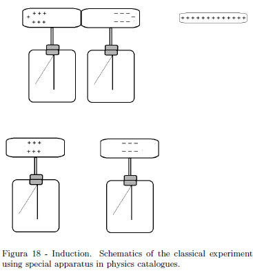
The classical demonstration experiment on the electrostatic induction uses two electroscopes with a long cylindrical conductor as it is drawn in the schematics in Fig. 18. It is argued as this demonstration using special apparatuses of physics catalogues is expensive. To complete the experiment, sign of charges on the dissected electroscopes' heads should be shown.
This experiment may be easily reproduced using Coke cans and Styrofoam cups using our electronic electroscope, as shown in Fig. 19.
3.7. Experiment 7. Introduction of the "capacity" concept
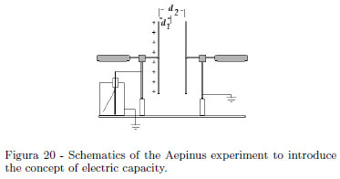
The schematics of the Aepinus experiment is shown in the Fig. 20. When the earthed plate is closer to the charged plate, the leaf of the electroscope falls. Having in mind that the capacity is the constant ratio between the charge and the electric potential of an insulated conductor, here the electroscope gives a drop of the potential when the plate is closer, namely the system's capacity increases. Without an Aepinus plane capacitor, a qualitative experiment is equally made with our "can electroscope". Charge the electroscope, so the aluminum foil is well diverted. Introduce, without touching the inner wall, a Coke can by hand. Aluminum foil falls, because the charge is unchanged, so the electrical potential of the system decreases. When extracting the Coke can, aluminum foil diverts as previously. This experiment can have some variation on theme [10]. Reference [10] rediscovers an old experiment, where an electroscope has a plate holding a chain. Rolling out the chain with a hook anchored to an insulating handle, the electroscope's leaf falls. Turning back the chain, the electroscope's leaf diverts as previously. Students should be convinced that capacity only depends by geometrical factors (and by the electric permittivity). One of us, in his teaching, used a Phywe Kölbe electrometer having a plate holding a chain. A student suggested that when charge density decreases, being constant the charge, decreases consequently the electrical potential. Because of the capacity definition as ratio between a charge Q and the body potential V ,

an electroscope can be used as a charge meter or as potential meter. Nowadays, Authors need of portable low cost experiments, so the system in the self explaining Figs. 21 and 22, works equally very well. A cooking aluminum sheet is folded upon itself many times. Two adhesive tape pieces ensure the end to the electroscope plate, adhesive tape at the top can be raised directly with your fingers being sufficiently insulated. In this demonstration is emphasized that capacity must depend on the geometry: an increase in superficial charge density yields an increase in the electrical potential.
3.8. Experiment 8. Dielectrics and capacitors
Figure 23 shows the Aepinus experiment inserting a dielectric slab. Authors showed this demonstration using a good Phywe Kölbe electrometer. Being fixed to the thickness of the slab the distance between plates and being fixed the charge, electroscopeâs leaf falls when dielectric slab is inserted and conversely, leaf diverts to initial status when dielectric slab is extracted. Dielectric polarization is reversible.
3.9. Observations on Aepinus experiment
Experiment may be shown at constant charge or at constant potential connecting plates to the terminals of a H.T. power supply. In this case, insert a micro ammeter between one terminal and the plate. Qualitatively it is shown a transfer of charge from the power supply to the plates and vice versa. Ask your students what happens:
a) to the electric field, to the potential, to the energy at constant charge Q varying the plate distance;
b) to the electric field, to the potential, to the energy at constant charge Q, inserting and leaving a dielectric slab;
c) to the charge, to the electric field, to the energy at constant potential V, varying the plate distance;
d) to the charge, to the electric field, to the energy at constant potential V, inserting and leaving a dielectric slab;
A discussion of the energetic feature is very interesting. The entire experiment requires a pair of hours.
3.10. Experiment 9. An observation on the most "trivial" electrostatic effect
It is the well-known effect of attracting light bodies like pieces of paper. Make sure that the table and the paper are dry. Ask your students about the cause of this attraction. Emphasize the difference between induction and polarization. A PVC pipe rubbed with duster attracts small pieces of paper and, equally, attracts small pieces of cooking aluminum sheet. Aluminum is attracted, adheres to the PVC pipe and, when touched, (earthed) remains adherent to negatively charged PVC. In the first case, polarization charges arises on the paper. In the second case, induced charge appears on the aluminum foil. The explication is simple in both cases. Charges closer to the charged rod are attracted with a force greater than the repulsive force on the charges in the opposite side. Now use a charged positively rod.
Ask your students why an aluminum little sheet is attracted but do not adhere to the positive charged rod. Why this not symmetric feature?
3.11. Experiment 10. Ionization by flames
In the old literature [11, 12] experiments on the ionization of a flame are highly considered also for educational purposes. The simplest experiment you can show uses a can electroscope, a candle and a PVC pipe (electrical conduit). Charge the electroscope by induction, introduce the charged rod and touch the external wall. Bring up a lighting candle near the can electroscope. Discharge appears evident. Ask your students how a flame discharges the electroscope (a flame is ionized gas and in the candleâs flame there are various particle of combustion). Discharging is independent by the sign of the charge and from the flame used. Remember the experiment of the bending flame in an intense electric field. Here the situation is reversed. Ions of the flame (of opposite sign to the sign of the charge on the electroscope) migrate toward the wall of the charged electroscope and neutralize its charge. Of course, Authors were not able to reproduce the simple and beautiful experiment in Ref. 11 with home-made experimental solutions.
3.12. Experiment 11. Charging in intense field
Introduce vertically in your can electroscope (previously well discharged) the Fun Fly Stick running just in the center being absolutely certain not to touch the wall. The electroscope charges rapidly of the same positive sign of the Fun Fly Stick. Ask your students why this happens.
3.13. Experiment 12. Ionization in small Neon lamps
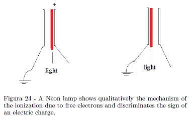
If your audience is a little group of students, a Neon lamp shows qualitatively the sign of the static charge [13, 14]and the cold emission of electrons. When one of the terminal of a small Neon lamp is touched using a piezoelectric lighter with a pith ball at the extreme and the other terminal is held in the hand, a bright flash occurs at one electrode. If a Fun Fly Stick is used, lighting of the lamp happens continuously. A Neon lamp consists of two closely spaced electrodes in a bulb containing Neon at low pressure, forming a gas discharge device. With reference to the Fig. 24 showing schematically the ionization mechanism, the negative electrode repels the free electrons in the bulb and the positive electrode attracts these free electrons. Ionization happens only near one of the two electrodes. A small Neon lamp acts as a quick device to discriminate the sign of an electric charge.
3.14. Experiment 13. Measurement of the force between parallel plates of a plane capacitor
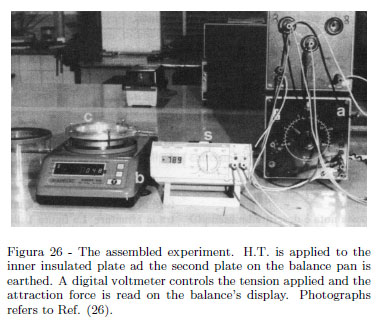
The experiment requires an electronic balance having a circular pan and a resolution 0.001 g. During his teaching, one of us used a Gibertini Europe 500 electronic balance having a 0.001 g resolution and a maximum load 500 g. Figure 25 shows the plane capacitor used. Two aluminum circular plates (workshopâs scraps) 10 mm thick and having 120 mm in diameter were used. Plates were partially hollowed by turning in order to adapt one of these plates to the balance pan. A plate is assembled on a circular Plexiglas ring where three treated holes 120º apart each other were made. Three leveling screws ensure a parallelism between plates. Distance d between plates is controlled using a 10 mm Plexiglas cylinder. One plate lies on the balance pan and the second plate over the fist plate; the three screws ensuring parallelism lean on the balance plane body as shown in Fig. 26 showing the assembled experiment. Three measures in the width 500-1500 V give a linear dependence of the force vs. V2 being V the tension applied. From a set of measurement it follows the measured value of the electric permittivity in vacuum (in air) with a relative uncertainty of about 12% as shown in an earlier paper [15]. Note as an electronic balance allows one a simple measurement of the force acting on dielectric slab [16, 17].
3.15. Experiment 14. Showing electric field lines
Recall the features of the field lines of a vector field v. These have v tangent to the field line at every point of it. So electric field has field lines identified with lines of force. This observation can be outlined when Magnetic Field is introduced, being lines of the magnetic field orthogonal to the force given by

where dF is the force acting on the straight wire of infinitesimal length dl oriented by the conventional versus of the current having intensityi and B is the so called magnetic induction vector. So magnetic field lines here are not lines of force.
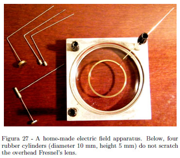
The experiment to show electric field lines is very simple and various complete apparatuses are found in catalogues of physics instruments. Electric field lines are shown using an overhead projector. Our home made apparatus uses an aluminum scrap (adapted with a little work of turning) ad a glass Petri dish as shown in Fig. 27. Two Plexiglas columns and binding posts as terminals complete the apparatus. Some electrodes are shown. The experiment requires no particular comments so the technical aspect is emphasized. The H.T. source was a Phywe D.C. power supply shown in the Fig. 27 giving up to 3 kV or 6 kV. Usually an electrical tension of about 6 kV gives good results. Using H.T. power supply, be sure that good insulated cable used do not touch the bench or the overhead projector. Use Castor oil (a sheet of 3 â 5 mm) and a very little amount of semolina grains. About 5 grains per centimeter squared give long regular chains showing field lines, namely a single pinch on the entire oil surface . The aluminum holder grounded gives the "infinite" for the field given by single point charge. Use both + and - H.T. terminals in order to shown the lines of opposite charges. Use caution in changing the electrodes, turning off the power supply, and shorts the terminals with the metal of an insulated screwdriver. With the electrode mounted, shown in Fig. 27, you should outline the movements of semolina grains during grains orientations in long chains disposed radially, while, inside the large conductor, no movements ad no orientations are observed. Recall the rough results of the Experiment 4: inside a close conductor there are no electrical effects (itâs the major consequence of the inverse square law). The use of a Petri glass dish is advantageous compared to Plexiglas dishes during the tedious task of washing. Use hot water and dish soap. In the last wash, use boiling water and NaOH.
One of the Authors (S.G.) regrets do not have taken photographs during his teaching. The experiment were well appreciated by students and the movements in chain of semolina suggest an introduction to the phenomena of dielectric polarization. Nowadays, beautiful âappletsâ showing electric field lines (and equipotential lines in two dimensional problems) are freely available on the web. In these âappletsâ it is pedagogically useful to choice the value of the charges. After showing the field of equal charges, choose a large charge and a charge very small. In Authorsâ opinion it is useful to explain the electric field definition as

where F is the Coulombâs force between a point charge Q (source of the field) and a small point charge q (so small that it doesnât introduce "perturbations" with its necessary presence).
3.16. Experiment 15. Again on the cylindrical electrophorus and the electroscope can
Ask your students how does the Voltaâs electrophorus work. It is simple: there are no relevant contacts between electrified pan and the metallic plate. Usually the dielectric pan has negative charge and charges by induction metallic plate as shown in Fig. 28 Grounding the upper surface of the metallic plate, negative charge is neutralized and a positive charge remains on the plate. No particular troubles. The same explanation happens for our cylindrical electrophorus schematically shown in Fig. 29. Let charge by induction a can electroscope using cylindrical electrophorus introducing the brass tube without touching the can. You may ground the external wall (neutralizing negative charges) or you can attempt to neutralize positive induced charge in the inner wall. Why, when touching the inner wall, always negative charge is neutralized?
3.17. Experiment 16. In thermo-electronic effect negative charges are generated (electrons)
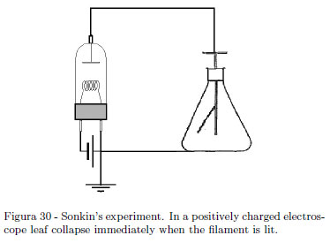
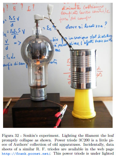
If you have the good fortune of an old vacuum tube still efficient, you can shown an interesting experiment showing that in thermoelectronic effect, negative charges are emitted from the cathode. Authors have the good fortune to have found an old vacuum power R.F. triode 3C200 still efficient. The tube is used as diode using a power supply giving at least 7.5 Ampere. The current in the filament used surely is under the (unknown) nominal current of the manufacturer but the effect is equally dramatic. The experiment was first described by S. Sonkin [18] in 1937. The basic philosophy is very simple: connect the anode of a vacuum tube (a diode) to an electroscope as shown in schematics of the Fig. 30. Let the electroscope charged negatively. Lighting the filament the electroscope remain charged. Now, charge positively the electroscope and light the filament. A quick discharge is observed. Lighted filament emits negative charges (thermo-electronic effect). Figure 31 shows our experimental setup. The can electroscope works very well; the power triode 3C200 is used as diode excluding the grid. A power supply giving about 7.5 Ampere is used to under lighting the filament and so prevent damages to this beautiful museum piece, but the effect is equally dramatic. The leaf divergence is scarcely view in the Fig. 31. In Fig. 32 no divergence is seen (in both cases look at where the leaf is hung.
3.18. Experiment 17. The mystery of the dissectible Leyden jar
The experiment, in essence, goes back to investigations of Benjamin Franklin. Franklinkâs conclusions are phenomenologically correct when stated as ". . . Which demonstrated the power to reside on the glass as glass. . . ". It is a well known experiment, a "classical" of the most spectacular experiments without a convincing simple explication if we go back into the Literature about the phenomenon.
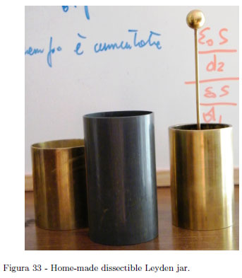
Surely a lot of free charge go into the surface of the dielectric as outlined in one of the old French Textbook [19] but it is the mechanism of this transfer not well known (as far of Authorsâ knowledge), but a lot of mystery are secondary sparks without dissecting Leyden jar. It occurs a bit of time interval to obtain secondary sparks. Only admitting that free charge go into the dielectric surface the secondary spark after dissection, and recombination are explained. The abundance of Literature about dissectible Leyden jar shows that some aspects are still of interest[20- 25]. Dissectible Leyden jar (two brass cylinders and a plastic tube may be realized using workshopâs scraps (see Fig. 33). Turning operation to adapt coaxial cylinders is required.
4. Conclusions
There are a lot of demonstration experiments on particular phenomenological effects particularly emphasized in XIX Century textbooks. A lot of experiments are only directed to show spectacular but not essential features (electrostatic dance, electrostatic bells, tower of the bolt, ignition of flammable vapors and so on. . . ). It was shown as a set of meaningful experiments does not necessarily require the purchase of special equipment from physics catalogues. In this paper we do not have exhausted all possible significant experiments, but experiments engaging home-made devices were emphasized. Experiments described were used in the past with classical apparatuses, while the same experiments performed with home-made solutions are used nowadays in special circumstances in a wide width of audience.
Materials and devices on the web
http://www.bbtrade.it/sfoglia.prodotti/sfere-per-oggettistica/0/0/index.html, stainless steel hollowed spheres supplier.
http://www.arborsci.com/prod-Fun_Fly_Stick_Science_Kit-1480.aspx, one of the many suppliers; see for European suppliers.
A less known source of XIX Century Physics textbooks at http://gallica.bnf.fr
References
[1] J. Frick, Physical Technics (Lippincot & CO, Philadelphia, 1861).
[2] G. G. Pegna, Am. J. Phys. 45, 218 (1977).
[3] D. S. Ainslie, "Am. J. Phys. 12, 43 (1944).
[4] S. Ainslie, Am. J. Phys. 26, 582 (1958).
[5] D. S. Ainslie, "Phs. Teach. 18, 530 (1980).
[6] Colin Siddons, Experiments in Physics (Basil Blackwell Ltd, Oxford, 1988), chap. 14.
[7] S. Ganci, Am. J. Phys. 62, 474 (1994). The use of an electronic electroscope was recently emphasized in Mihai P. Dinca, Am. J. Phys. 70, 217 (2011).
[8] Oreste Murani, Trattato Elementare di Fisica (Hoepli, Milano. 1929), v. 2, p. 344.
[9] A. Cortel, Phys. Teach. 37, 447 (1999).
[10] F. Noschese, Phys. Teach. 48, 621 (2010).
[11] F. Maccarrone, Il Nuovo Cimento, serie V, 15, 423 (1908).
[12] A. Bernini, Il Nuovo Cimento, serie V, 18, 301 (1909).
[13] J.W. Layman and D.J. Rutledge, Phys. Teach. 10, 49 (1972).
[14] X. Yong Chen and X. Wang, Phys. Teach. 37, 344 (1999).
[15] S. Ganci, G. Fis. 39, 120 (1998).
[16] R.E. Benenson, Am. J. Phys. 59, 763 (1991)
[17] S. Ganci, G. Fis. 40, 185 (1999).
[18] S. Sonkin, Am. J. Phys. 5, 41 (1937).
[19] M. Jamin, Traité de physique de l'école Polytechnique (Gauthier-Villars, Paris, 1980), Tome 4, p. 209-213.
[20] J. Hopkinson, Phil. Trans. of Royal Soc. London 166, 489 (1876).
[21] J. Hopkinson, Phil. Trans. of Royal Soc. London 169, 17 (1877).
[22] B. Gross, Am. J. Phys. 12, 324 (1944).
[23] J. Zeleny, Am. J. Phys. 12, 329 (1944).
[24] G.B. Huff, Phys. Teach. 24, 460 (1986).
[25] J. Sumner Miller, Phys. Teach. 24, 460 (1986
Recebido em 10/10/2011; Aceito em 23/1/2012; Publicado em 20/4/2012
- [1] J. Frick, Physical Technics (Lippincot & CO, Philadelphia, 1861).
- [2] G. G. Pegna, Am. J. Phys. 45, 218 (1977).
- [3] D. S. Ainslie, "Am. J. Phys. 12, 43 (1944).
- [4] S. Ainslie, Am. J. Phys. 26, 582 (1958).
- [5] D. S. Ainslie, "Phs. Teach. 18, 530 (1980).
- [6] Colin Siddons, Experiments in Physics (Basil Blackwell Ltd, Oxford, 1988), chap. 14.
- [7] S. Ganci, Am. J. Phys. 62, 474 (1994).
- The use of an electronic electroscope was recently emphasized in Mihai P.
- Dinca, Am. J. Phys. 70, 217 (2011).
- [8] Oreste Murani, Trattato Elementare di Fisica (Hoepli, Milano. 1929), v. 2, p. 344.
- [9] A. Cortel, Phys. Teach. 37, 447 (1999).
- [10] F. Noschese, Phys. Teach. 48, 621 (2010).
- [11] F. Maccarrone, Il Nuovo Cimento, serie V, 15, 423 (1908).
- [12] A. Bernini, Il Nuovo Cimento, serie V, 18, 301 (1909).
- [13] J.W. Layman and D.J. Rutledge, Phys. Teach. 10, 49 (1972).
- [14] X. Yong Chen and X. Wang, Phys. Teach. 37, 344 (1999).
- [15] S. Ganci, G. Fis. 39, 120 (1998).
- [16] R.E. Benenson, Am. J. Phys. 59, 763 (1991)
- [17] S. Ganci, G. Fis. 40, 185 (1999).
- [18] S. Sonkin, Am. J. Phys. 5, 41 (1937).
- [19] M. Jamin, Traité de physique de l'école Polytechnique (Gauthier-Villars, Paris, 1980), Tome 4, p. 209-213.
- [20] J. Hopkinson, Phil. Trans. of Royal Soc. London 166, 489 (1876).
- [21] J. Hopkinson, Phil. Trans. of Royal Soc. London 169, 17 (1877).
- [22] B. Gross, Am. J. Phys. 12, 324 (1944).
- [23] J. Zeleny, Am. J. Phys. 12, 329 (1944).
- [24] G.B. Huff, Phys. Teach. 24, 460 (1986).
- [25] J. Sumner Miller, Phys. Teach. 24, 460 (1986
Publication Dates
-
Publication in this collection
25 Oct 2012 -
Date of issue
June 2012
History
-
Received
10 Oct 2011 -
Accepted
23 Jan 2012