Abstracts
The most expeditious method for the design of concrete beams under fire situation is the tabular method, presented by the Brazilian standard ABNT NBR 15200:2012. Albeit simple, this method constrains the engineer's work, as it prevents him to seek alternative solutions to the few tabulated values. Yet, the Brazilian standard allows employing more advanced methods. Hence, the purpose of this work was to perform a thermal and structural analysis of beams with several widths, heights, covers and diameters/layouts of steel reinforcement (upper and lower). From those results, graphs were constructed, associating the ratio between the applied bending moment in fire over the resistance bending moment at ambient temperature, for the fire resisting time of each situation. These graphs also allow taking into account the redistribution of moments from positive to negative, which will lead to savings in the solution found.
fire; beam; concrete; design; thermal analysis
O método mais expedito para o dimensionamento de vigas de concreto em situação de incêndio é o método tabular, apresentado na ABNT NBR 15200 [1]. Apesar de simples, esse método restringe o trabalho do engenheiro, uma vez que o impede de buscar soluções alternativas aos poucos valores tabelados. Contudo, a norma brasileira permite empregar métodos mais avançados. Sendo assim, o objetivo deste trabalho consistiu em realizar uma análise térmica e estrutural de vigas com diversas larguras, alturas, cobrimentos, diâmetros e disposições de armaduras (inferiores e superiores). A partir dos resultados, foram construídos gráficos que associam a relação entre o momento fletor solicitante em incêndio e o momento fletor resistente à temperatura ambiente, ao tempo de resistência ao fogo de cada situação. Esses gráficos permitem também levar em conta a redistribuição de momentos, do positivo ao negativo, o que conduzirá à economia na solução encontrada.
incêndio; viga; concreto; dimensionamento; análise térmica
Concrete beams fire design using graphs co
G. B. M. L. Albuquerque; V. P. Silva
Escola Politécnica da Universidade de São Paulo, São Paulo, SP, Brasil. gabriela.lins@usp.br, valpigss@usp.br
ABSTRACT
The most expeditious method for the design of concrete beams under fire situation is the tabular method, presented by the Brazilian standard ABNT NBR 15200:2012. Albeit simple, this method constrains the engineer's work, as it prevents him to seek alternative solutions to the few tabulated values. Yet, the Brazilian standard allows employing more advanced methods. Hence, the purpose of this work was to perform a thermal and structural analysis of beams with several widths, heights, covers and diameters/layouts of steel reinforcement (upper and lower). From those results, graphs were constructed, associating the ratio between the applied bending moment in fire over the resistance bending moment at ambient temperature, for the fire resisting time of each situation. These graphs also allow taking into account the redistribution of moments from positive to negative, which will lead to savings in the solution found.
Keywords: fire, beam, concrete, design, thermal analysis.
1. Introduction
Fire structural engineering is a recent area in Brazil and the technical standards related to this topic only use simplified methods to verify the safety of structures subjected to this accidental action. For the design of reinforced concrete beams in fire, the ABNT NBR 15200 [1] standard, inspired by the European standard Eurocode 2 part 1-2 [2], details only the tabular method (tables 1 and 2), in which it is only necessary for the beams to meet the minimum dimensions in width (bmín) and distance between the lower longitudinal reinforcement axis and the heated face of the concrete (c1), as shown in figure 1. These dimensions are a function of time required for fire resistance (TRRF), obtained from the type of occupation/use and the height of the construction. The tables that present these values are found in the Technical Instructions (IT) of the Fire Department in each Brazilian State.
The Brazilian standard ABNT NBR 15200 [1] states that in the tabular method:
▪ The hypothesis of beams heating on three faces (sides and bottom) was considered, under slabs. However, the values may also be used in case of beams heated on four faces, provided that their height is not less than bmín and the cross-sectional area of the beam is not less than 2 bmín2;
▪ There is a concentration of temperature close to the edges of the underside of the beams. For this reason, on sections with only one layer of reinforcement and width not exceeding the bmín indicated in column 3 of table 1 and column 2 of table 2, the distance between the longitudinal reinforcement axis of the corner and the side concrete face in fire (c1l) at the bottom of the beams must be 10 mm larger than c1 given by the aforementioned tables, or for reinforced concrete, specify corner bars with a diameter immediately higher, according to ABNT NBR 7480 [3], to the calculated. The possibility of this alternative was demonstrated in Silva [4];
▪ The values shown in table 2 can only be used if the coefficient of moments redistribution at room temperature respects the limits set in ABNT NBR 6118 [5]. Otherwise, table 1 should be used;
▪ When the reinforcement bars are arranged in layers, the average distance to the concrete face (c1m) must obey the value c1mín tabulated. The c1m value should always be the lowest between the values indicated in equations 1 and 2.
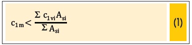

Where: c1m is the average distance to the concrete face for reinforcement bars arranged in layers; c1vi is the distance from bar i, of area Asi, to the bottom of the beam and c1hi is the distance of bar i, of area Asi, to the nearest side face.
It is also added that all tables were compiled for steel CA-25, CA-50 or CA-60 passive reinforcement, such that, in the centroid of the reinforcement, the temperature does not reach 500 °C (Eurocode 2 part 1-2 [2]).
As can be seen, this method, albeit practical, constrains the engineer, since it prevents him from studying the problem and from proposing different results. Therefore, in order to create tools to facilitate the work and contribute to this study area in our country, the objective of this research was to develop alternative solutions to the tabular method, based on thermal and structural analysis, considering that the standards also allow the use of more advanced design methods.
2. Graphic method
Owing to the precision of the results, more advanced methods require specific software that are rarely used in design offices. For this reason, the option was to conduct a thermo-structural analysis of beams and to present the results in graphical form for ease of use. The graphs illustrated in section 2.3 are completed in Albuquerque [6] and Silva [7]. In this work, the Swedish Super Tempcalc software, developed by Fire Safety Design (FSD [8]), was used.
2.1 Thermal analysis
By means of the finite element method, the thermal analysis was developed for models of beams with the following characteristics:
▪ Rectangular sections with 14 cm, 19 cm, 25 cm, 30 cm and 35 cm in width and 40 cm, 50 cm, 60 cm and 70 cm in height, all overlaid by a 5-cm thick and 60-cm wide slab, as illustrated in figure 2;
▪ Heating as per ISO 834 standard fire [9], on three faces of the beam (side and bottom) and under the slab. The face not exposed to the fire was considered adiabatic for safety purposes (figure 2);
▪ Physical and thermal parameters of the concrete, variable with temperature, in compliance with the equations indicated in ABNT NBR 15200 [1]: thermal conductivity (λc, θ), specific heat (cp, θ) for 1.5% relative moisture and density (ρc, θ), adopting ρ = 2400 kg/m3 at room temperature, according to ABNT NBR 6118 [5];
▪ Heat transfer coefficient by convection (αc) equal to 25 W/m2 oC and resulting emissivity (εr) on the faces exposed to fire 0.7, recommended values in ABNT NBR 15200 [1];
▪ Domain discretized by a mesh of four-node rectangular elements with sides of 0.005 m. Time step, the increment of time for the thermal analysis, taken equal to 0.002 h, the value that led to satisfactory results for preliminary thermal analysis for time intervals of usual fires and boundary conditions (FSD [8]).
About the dimension of the slabs, a relatively small thickness was considered for safety purposes, because the beams that will be sized through the graphs will have, at least, 5-cm thick slabs, which is the lowest value indicated by ABNT NBR 6118 [5] with respect to solid slabs, in this, case the roof ones, not cantilever.
Considering that the increase in thickness is directly proportional to the mass of concrete that absorbs heat, the beams that have thicker slabs will be in a less critical situation when compared to those that were used in the development of the graphic method.
Thus, from these input data previously mentioned, the temperature field with respect to the time for the beams under slabs was determined (figure 3).
2.2 Structural analysis
For this analysis, the following were considered:
▪ Partial factors for strength (γcand γs) equal to 1.4 (concrete) and 1.15 (steel) for room temperature and equal to 1.0 (γc,fi and γs,fi) for both materials in fire situation, following ABNT NBR 6118 [5] and ABNT NBR 15200 [1], respectively;
▪ Reducer of the design value of the compressive strength of concrete at room temperature (α) equal to 0.85 and in fire situation (αfi) equal to 1.0, according to ABNT NBR 6118 [5] and FIB/CEB [10], respectively;
▪ Reinforcement diameter of 10 mm, 12.5 mm, 16 mm, 20 mm and 25 mm, arranged in one and two layers, positive and negative, with covers of 25 mm, 30 mm and 40 mm (figure 4); CA-50 steel; number of reinforcements possible for each width, according to the values of minimum free spacing between the faces of the longitudinal bars, as proposed by ABNT NBR 6118 [5]; stirrups diameter of 5 mm;
▪ For the purposes of processing, the characteristic strength of concrete to compression (fck) equal to 25 MPa was admitted. However, due to a simplification favorable to safety, adopted in the calculations made by Super Tempcalc, the results presented in 2.3 are independent of the value of fck. Therefore, it is only recommended that this value be less than or equal to 50 MPa, since high-strength concrete is outside the scope of this research.
▪ Effects of thermal deformations are neglected, according to ABNT NBR 15200 [1]. Furthermore, no limit specific strains were imposed both on concrete and on steel (FSD [8]). Introducing this information in the structural module of Super Tempcalc and from the temperature field generated in the thermal analysis, parameter µ was determined, indicated in equation 3, as a function of heating time.
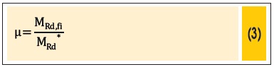
Where: µ is the relative moment; MRd* e MRd,fi correspond to the design resistance bending moments of the concrete section, at room temperature and in fire situation, respectively, both with no consideration of limit strains.
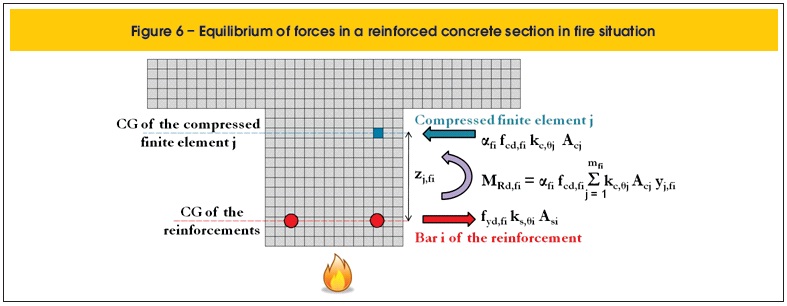
Such moments were determined by the equilibrium of forces, the only hypothesis of calculation of the program (equations 4 and 5 / figures 5 and 6). It is worth noting that the peak stress was considered in each one of the compressed concrete finite elements and, in the same way, total plastic strain was considered for the steel in the reinforcements, disconsidering the compatibility between deformations.

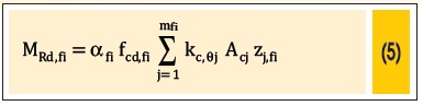
Where: α and αfi are reducers of the design values of the compressive strength of concrete at room temperature and under fire conditions, respectively; fcd and fcd,fi are the design strength to compression of the concrete at room temperature and in fire, respectively; kc,θj is the strength reduction factor at temperature θ of the compressed finite element j; Acj is the area of the compressed finite element j; zj and zj,fi are the distances between the CG of the compressed finite element j and the horizontal line that goes through the CG of the reinforcements at room temperature and under fire situation, respectively.
2.3 Results
The graphs presented herein, which consist of results from the more advanced method for sizing, depend on parameter µ shown in equation 6.

Where: MSd,fi is the design applied bending moment in case of fire and MRd is the design resistance bending moment of the concrete section at room temperature.
Safety is met when MSd,fi ≤ MRd,fi. Therefore, assuming MSd,fi = MRd,fi in parameter µ provided by Super Tempcalc, it is possible to find the maximum time for fire resistance (TRF) of the structural element.
Note that, moreover, for simplicity, M*Rd is replaced by MRd in the expression of µ, where MRd is the design value, i.e., the one in which limit strains are imposed on materials, which can be inserted by the engineer as input since, for MRd ≤ MRd*, the graphs remain in favor of safety.
The expression for the ultimate accidental combination of actions recommended by the ABNT NBR 8681 [11] (equation 7), in which the effects of thermal strains are neglected, can be used for calculating MSd,fi.

Where: Fd,fi is the design value of action in accidental combination; FGi,k is the characteristic value of permanent action i; FQj,k is the characteristic value of variable action j and ψ2 is the combination factor used to determine the reduced values of the variable actions (according to ABNT NBR 8681 [11], for accidental combinations, in which the main action is fire, reduction factor ψ2 can be reduced by multiplying it by 0.7, as indicated in the equation under analysis).
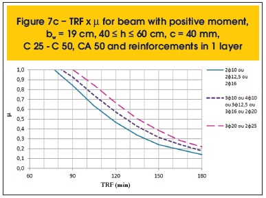
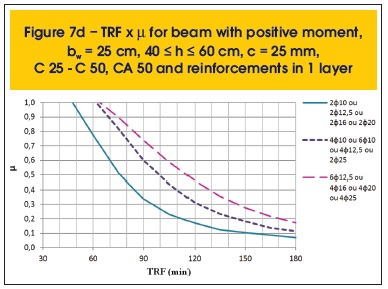
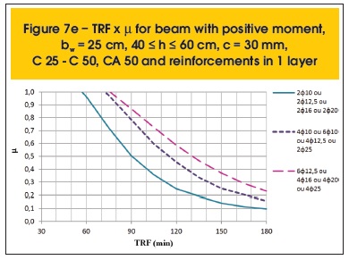
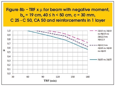
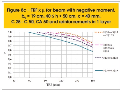
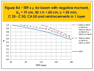
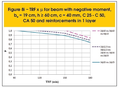
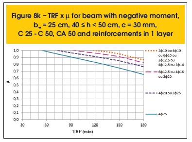
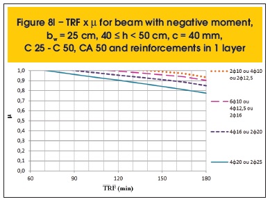
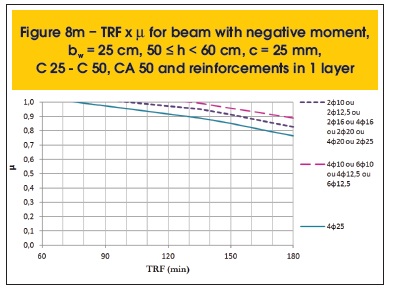
The following are some results compiled (figures 7a to 8r). Besides parameter µ, the variables related to the determination of TRF are: position of the moment (positive or negative), the beam width (bw), height (h), cover thickness (c), concrete and steel categories and distribution of reinforcement (1 or 2 layers).
2.4 Moments redistribution
The structural behavior of beams in fire depends crucially on how they are supported. Simply supported beams are more susceptible to thermal action, as they do not have the ability to redistribute their moments and create a favorable situation for fire resistance, unlike continuous beams that have this property.
A continuous beam is exposed to fire by the underside of its spans, while the top remains relatively cool. This situation is favorable, since the upper fibers of the beam, with small strength impairment, are able to support higher negative moments, while the lower fibers, with reduced strength due to the exposure to fire, will support an also reduced positive moment. Therefore, there may be a redistribution of moments from positive to negative (figure 9).
The graphic method presented here allows incorporating the redistribution of moments for continuous beams in fire. For this, it is only necessary to apply the coefficient of redistribution (δ) in the positive applied bending moment in case of fire (MSd,fi+) and calculate the negative applied bending moment in case of fire (MSd,fi-) imposing the equilibrium of forces. In the following section, further details on this subject are presented.
2.5 Application example
In the static scheme of the beam, "L" is the span length and "pk" the characteristic value of the uniformly distributed load. The cross-section was taken according to the models used in the graphic method, considering one beam under a 5-cm thick, 60-cm wide slab (for security), as illustrated in Figure 10. 25 mm of cover, stirrups diameter of 5 mm, concrete fck equal to 25 MPa and steel fyk equal to 500 MPa were stipulated. Due to the symmetry of the spans, calculations were performed only for a portion of the structure.
The redistribution of moments at room temperature, from negative to positive, was performed according to ABNT NBR 6118 [5]. Analyzing the position of the neutral line in section (x), its relationship with the redistribution coefficient (δ) and considering a structure of fixed nodes, the maximum allowed redistribution was 25% (δ = 0.75).
The diagrams of the design bending moments and the results of the sizing at room temperature, before and after the redistribution of moments, for the beam under study are shown in figures 11 and 12. In the two cases, both the positive and negative sections are in domain 2.
From the adopted steel section, given the redistribution, it is possible to calculate the resistance bending moments, negative and positive, which are needed in parameter μ, used as input in the graphs.
Positive resistance bending moment (MRd+): 89 kN m
Negative resistance bending moment (MRd-): 112.5 kN m
In the verification of the structure in fire situation, equation 7 was used for determining of the design value of the uniformly distributed load. 60% permanent actions and 40% variable were considered. It was assumed that this was a beam located in a residential building (ψ2 = 0.7 x 0.3 = 0.21; value recommended by ABNT NBR 8681 [11]). The new load (pd,fi) is shown in figure 13.
At elevated temperatures, the concrete beams become more ductile. Therefore, the coefficient of moments redistribution in fire situation can be greater than that applied at room temperature, since the capacity of rotation of supports is increased under these conditions.
However, for simplicity and for safety, we adopted the same coefficient for redistributing moments, now from positive to negative, used in the previous analysis (δ = 0.75).
Hence, we calculated the new negative moment, illustrated in figure 14, by means of equation 8, which was also used in the calculations at room temperature, but with different safety coefficients. The diagrams of the design bending moments in fire situation, before and after the redistribution, are shown in figures 15 and 16.
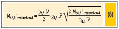
Where: L is the span of beam; MSd,fi+redistributed and MSd,fi-redistributed are the design applied redistributed bending moments in fire situation, positive and negative, respectively, and pd,fi is the design value of the uniformly distributed load in fire situation.
Parameters µ will thus bear the following values:
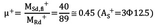
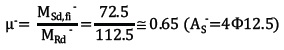
Considering the redistributed moments:
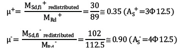
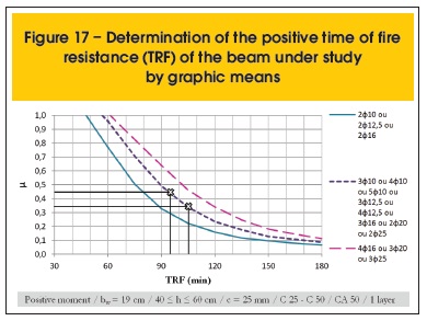
From the graphs shown in figures 17 and 18, for the first case studied, TRF+ = 95 min and TRF- ≥ 180 min. Therefore, TRFbeam = 95 min. In the second case, in which the redistribution of moments was applied, TRF+ = 105 min and TRF- = 150 min. Consequently, TRFbeam = 105 min.
By means of the tabular method (table 2), a continuous beam with bw = 190 mm and c1 = 36.25 mm (As+ = 3Ф12.5; lower longitudinal reinforcement) would have, by linear interpolation, TRFbeam = 104 min. However, according to ABNT NBR 15200 [1], in sections with only one layer of reinforcement and width not exceeding, as per TRRF, value bmín indicated in column 2 of table 2 (bw = 190 mm < bmín = 273.5 mm, this value calculated by linear interpolation), some changes in design should be made: increase c1l at the bottom of the beams by 10 mm or specify corner bars with a diameter immediately above. If these changes are not met, TRF must be recalculated, considering c1 reduced by 10 mm, for safety reasons. Therefore, in this situation, TRFbeam = 86 min.
As noted, the comparison of results obtained by means of graphical tools and the tabular method is not immediate, due to the large number of variables. Due to the simplicity of the method presented in the Brazilian standard, it is recommended, a priori, to use it for design. If the requirements regarding the time of fire resistance (TRF) are not met, one can use the graphic method as a tool for solving the problem, for the satisfactory results presented in this application example, when applied the redistribution of moments in a fire situation.
3. Conclusions
ABNT NBR 15200 [1] indicates a simple method for designing beams under fire conditions: the tabular. This method, albeit practical, restricts the engineer's work for not allowing alternatives for design. From structural and thermal analysis, using the finite element method, graphical tools were developed that allow finding more realistic structural solutions than those prescribed by the tabular method. Part of them we presented in this article. In fire, the floors (slab on beams) are heated on the underside. Thus, it is possible to redistribute part of the positive moments in the beams for the negatives. The same graphs may also be used in the case of employing this redistribution of moments. In the application example, the graphical method showed that it may, in a given situation, be more economic than the tabular one.
4. Acknowledgments
The authors thank FAPESP - the State of São Paulo Research Foundation, CAPES - Coordination for the Improvement of Higher Education Personnel and CNPq - Brazilian National Council of Scientific and Technological Development.
5. References
Received: 13 Jun 2012
Accepted: 07 Apr 2013
Available Online: 12 Aug 2013
- [01] ASSOCIAÇÃO BRASILEIRA DE NORMAS TÉCNICAS. Projeto de estruturas de concreto em situação de incêndio. NBR 15200:2012. Rio de Janeiro, 2012. 52 p.
- [02] EUROPEAN COMMITTEE FOR STANDARDIZATION. EN 1992-1-2: Eurocode 2: design of concrete structures - part 1.2: general rules - structural fire design. Brussels: CEN, 2004. 97 p.
- [03] ASSOCIAÇÃO BRASILEIRA DE NORMAS TÉCNICAS. NBR 7480: aço destinado a armaduras para estruturas de concreto armado - especificação. Rio de Janeiro, 2007. 13 p.
- [04] SILVA, V. P. Dimensionamento de vigas de concreto armado em situação de incêndio. Aprimoramento de algumas recomendações do Eurocode. Revista Ibracon de Estruturas e Materiais, São Paulo, v. 4, n. 2, p. 277303, junho 2011.
- [05] ASSOCIAÇÃO BRASILEIRA DE NORMAS TÉCNICAS. NBR 6118: projeto de estruturas de concreto - procedimento. Rio de Janeiro, 2007. 221 p.
- [06] ALBUQUERQUE, G. B. M. L. Dimensionamento de vigas de concreto armado em situação de incêndio. 2012. 244 p. Dissertação (Mestrado) - Escola Politécnica, Universidade de São Paulo, São Paulo, 2012.
- [07] SILVA, V. P. Projeto de estruturas de concreto em situação de incêndio. São Paulo: Edgard Blücher, 2012. 238 p.
- [08] FSD - Fire Safety Design. TCD 5.0 User's manual. Lund: Fire Safety Design AB, 2007. 129 p.
- [09] INTERNATIONAL ORGANIZATION FOR STANDARDIZATION. ISO 834: Fire-resistance tests: elements of building construction - part 1.1: general requirements for fire resistance testing. Geneva, 1999. 25 p. (Revision of first edition ISO 834:1975).
- [10] FÉDÉRATION INTERNATIONALE [du] BÉTON (FIB). Fire design of concrete structures: structural behaviour and assessment. Lausanne: International Federation for Structural Concrete, 2008. 209 p. (Bulletin. FIB; 46).
- [11] ASSOCIAÇÃO BRASILEIRA DE NORMAS TÉCNICAS. NBR 8681: ações e segurança nas estruturas. Rio de Janeiro, 2003. 18 p.
Publication Dates
-
Publication in this collection
27 Aug 2013 -
Date of issue
Aug 2013
History
-
Received
13 June 2012 -
Accepted
07 Apr 2013