
Abstract
Beams are subject a flexure and shear, with the last as the theme of this research. The purpose of this paper is to analyze specifications for the shear design of concrete block structural masonry beams, based on an extensive literature review and experimental tests here reported. From this scope, specifications for revision of Brazilian standardization are suggested. In the theoretical part, literature review from both national and international researchers were considered and the specifications of Brazilian standards, in addition to North American, Australian, Canadian and European, ABNT NBR 15961-1/2011, ABNT NBR 6118/2014TMS 402/2016, AS3700/2001, CSA S304/2014 and EuroCode6.1/2001, respectively. To analyze and validate the specifications of the literature, an experimental program was carried out assessing ten concrete block masonry beams results tested mainly to shear loads. Two-course high beams with three vertical load positions (position a/d) and two transverse reinforcement rates were tested. The specifications from the Brazilian and European standards led to considerably higher results than the experimental results, while those presented in the standards TMS 402/2016, AS3700/2001, CSA S304/2014 and NBR6118/2014 lead to results close to those obtained experimentally. As a conclusion, it can be noted that the rupture pattern is similar to that expected for reinforced concrete beams, the cracks were conditioned by the position of the loading point and by the mortar joints positions, the increase in the transverse reinforcement ratio led to an increase in the shear force. Results indicate that the consideration of apparent increase in shear strength by the ratio M ⁄ (V∙d) is not consistent. Eliminating this recommendation, considering the masonry shear strength equal to 0.35 MPa, limiting the stirrups tension to 0.90 of fyk and considering the contribution of the longitudinal reinforcement, it was possible to estimate the shear value at the rupture of each beam between 73% to 106% of the values verified in the tests.
Keywords:
beam; masonry; reinforced masonry; shear
Resumo
Vigas são submetidas à flexão e cisalhamento, sendo esse último esforço o tema desta pesquisa. O objetivo deste trabalho é analisar especificações para dimensionamento ao esforço cortante de vigas de alvenaria estrutural em blocos de concreto, a partir de extensa avaliação da literatura e de ensaios experimentais aqui relatados. A partir desse escopo, são sugeridas especificações para revisão da normalização brasileira. Na parte teórica, foram considerados trabalhos anteriores tanto nacionais quanto internacionais e as prescrições das normas brasileiras NBR15691-1/2011 e NBR 6118/2014, além da norte-americana, australiana, canadense e europeia, TMS 402/2016, AS3700/2001, CSA S304/2014 e EuroCode 6.1/2001, respectivamente. Com intuito de analisar e validar as especificações da literatura foi realizado um programa experimental de análise de dez vigas de alvenaria com blocos de concreto submetidos principalmente ao esforço cortante. Foram consideradas vigas de duas fiadas, três posições da carga vertical, variando a/d, e duas taxas de armadura transversal. Na análise dos ensaios verificaram-se semelhanças no comportamento último das vigas de alvenaria armada com a teoria proveniente das vigas de concreto armado, com algumas particularidades de fissuração na região das juntas de argamassa. Além disso, as especificações estabelecidas pela norma brasileira e europeia levaram a resultados consideravelmente maiores do que os resultados experimentais, enquanto que os presentes nas normas TMS 402/2016, AS3700/2001, CSA S304/2014 e NBR6118/2014 levam a resultados próximos aos obtidos experimentalmente. Como conclusão pode-se destacar que o padrão de ruptura é semelhante ao esperado para vigas de concreto armado, as fissuras foram condicionadas pela posição do ponto de aplicação do carregamento e pelas juntas de argamassa, o aumento da taxa de armadura transversal levou ao aumento da força cortante de ruptura. Os resultados indicam não ser consistente a consideração de aumento aparente da resistência ao cisalhamento pela relação M ⁄ (V∙d). Eliminando-se essa recomendação, considerando a resistência da alvenaria igual a 0,35 Mpa, limitando a tensão nos estribos a 0,90 de fyk e considerando a contribuição da armadura longitudinal, foi possível estimar o valor de cortante na ruptura de cada viga entre 73% a 106% dos valores verificados nos ensaios.
Palavras-chave:
viga; alvenaria; alvenaria armada; cisalhamento
1. Introduction
As the use of the structural masonry system in concepts that lead to efforts beyond axial compression, as is the case of beams subjected to bending and shearing, it is noted the importance of an improvement in the dimensioning criteria for this type of element.
Based on studies by several authors, it is evident the existence of gaps in the knowledge of the behavior of reinforced masonry beams. Sarhat and Sherwood (2011) indicate that masonry beams are structural elements that are used to overcome spans over openings in walls such as doors and windows. In contrast, it is common in Brazil to use beams to support slabs and other elements, in spans considerably longer than the usual doors and windows spans.
These beams can be constructed with the same blocks that are used in the wall construction and, in other situations, U-shaped cross-section beam blocks can be used in. According to Ring et al. (2012), the use of beam blocks in the first has the objective of creating a continuous “void” where it is possible to position the longitudinal reinforcement.
ABNT NBR 15961-1, part 3.14 defines beam as a linear element that resists predominantly to flexion and whose span is greater than or equal to three times the height of the cross section.
In relation to shear, it is possible to design beam elements without transverse reinforcement, although Parsekian et al (2012) indicate the use of non-stirrup beams only when it is composed of only one masonry course. Fereig (1994) points out the existence of high shear forces causing an early and fragile rupture. Due to the shear brittle failure, it is advisable to use a minimum shear reinforcement in masonry with more than one course. Landini (2001) reports that a reinforced masonry beam shear stress behavior resembles that of a reinforced concrete beam, a fact corroborated by Fereig (1994).
This work reports the study on concrete-block structural masonry beams. The theoretical part includes assessing specifications present in the Brazilian codes NBR 15691-1 / 2011 and NBR 6118/2014, in addition to North American, Australian, Canadian and European codes, TMS 402/2016, AS3700 / 2001, CSA S304 / 2014 and EuroCode 6.1 / 2001, respectively. The experimental program included the analysis of ten concrete masonry beams tested to mainly shear loads, aiming to analyze and validate the specifications from the literature review. Tests on two-course beams contemplate varying the load position related to the support distances and varying the transversal reinforcement ratio. From the literature review and from the testing results the shear behavior of reinforced masonry is reported.
1.1 Research significance
In Brazil there was a huge growth in the use of structural masonry in recent years, since this constructive method has several advantages. According to Camacho (2006) some of these benefits are:
-
Lower diversity of materials used: this reduction is due to fewer subcontractors in the work;
-
Reducing the diversity of skilled labor: since only the manpower that will perform the masonry must receive training.
-
Higher speed of execution;
-
Structural robustness: increased resistance to pathological damage and greater safety reserve front partial failures.
These benefits have led to frequent designs of beams in reinforced masonry. The finding of gaps in the knowledge of the behavior of these elements, as highlighted in the previous paragraph, justify this work.
2. Beam shear behavior
In many cases a simplification of the real model is made to design and detail a structure. When dealing with dimensioning beams this is no different. According to Fusco (1995), in the case of elements subjected to bending moments and shear forces a truss model is admitted, a model which was idealized by Ritter and Mörsch in 1948.
From Figure [1] it can be observed that the top chord is represented by the concrete while the bottom chord is represented by the longitudinal reinforcement. It is necessary to ensure the model balance, and this is done by the presence of the transverse reinforcement. Mörsch (1948) observed that this model is only applied when the beam presents cracks, that is, when the beam is at its cracked-elastic stresses stage.
As for the distribution of shear forces toward the support, Fusco (2008) point that the stresses trajectory in the region close to the supports does not obey the inclination proposed by the truss analogy. This distribution occurs into two distinct trajectories, as can be seen in Figure [2].
According to Fereig (1994), the shear rupture is fragile. In addition to Fereig (1994) the authors Neis and Loefller (1983) present the same conclusion, as is observed in Figure [3].
In the case of beams without transverse reinforcement, shear design is even more important and, according to Sarhat and Sherwood (2011), it is even more relevant, and this failure type will likely determine the beam load capacity.
As for the cracking behavior, it is possible to distinguish it as to the presence or not of transverse reinforcements. In cases of transverse reinforcement absence or in cases where its spacing is exaggerated, Fusco (2008) infers that the shear strength will be defined by the material tensile strength. In these cases, the crack path, according to Landini (2001), starts at the lower edge of the beam to the upper edge with a slope around 45º, as verified by Mörsch. In this situation, the cracks are from the shear stress and are inclined cracks. Due to this nomenclature, shear rupture is also called diagonal tension failure. In cases where the transverse reinforcement is correctly placed, shear rupture may still occur. Fusco (2008) describes four distinct shear failure types , as follows:
-
Shear-Compression Rupture (RFCC): when there is a rupture of diagonal concrete strut;
-
Shear-Tension Rupture (RFCT): when the transverse reinforcement strength is overcome by the design shear force of calculation with a tensile rupture;
-
Shear-Flexure Rupture (RSBF): from the interaction between shear force and bending moment in the vicinity of concentrated loads. In these casesthe large increase of the local compression stresses cause a failure shear at the top chord. This rupture is avoided by limiting concentrated forces values;
-
Longitudinal Flexural Reinforcement (FRLR): occurs when the diagonal concrete connecting rods that are supported on the trailed sheath (longitudinal reinforcement) cause high bending stresses in these reinforcements.
Mechanism of Shear resistance Mechanisms of Shear resistance are ways to ensure that the reinforced concrete parts will not failure in the Ultimate Limit State (ELU) due to shear forces. The cracking path of a reinforced concrete beam and a masonry beam is very similar, since they are perpendicular to the axis of the element and the beginning of the propagation is from the bottom chord.
The shear resistance of a cracked beam due in simple bending can occur by in two distinct mechanisms which are called maximum and minimum cooperation of concrete between cracks.
Maximum concrete cooperation between cracks is defined as the mechanism where the forces are absorbed by the material by three different mechanisms, that are
-
V1 - portion transmitted by the compressed top chord of the element;
-
V2 - portion transmitted through the flexural crack;
-
V3 - portion transmitted through the bending fissure by longitudinal reinforcement (dowel action).
According to Fusco (2008), the minimum concrete co-operation model between cracks has been admitted since the early days of reinforced concrete. It consists of the complete transmission of the shear force through the top chord. In addition, there is the consideration that two adjacent cracks form a fixed corbel in the strut. Because of the fixed corbel it can occur a variation of the tensile force along the longitudinal reinforcement length.
Figure [4] presents how the contribution of each shear resistant mechanism occurs.
Nagato et al. (2003) report an experimental study assessing the shear strength by dowel action on six reinforced concrete beams. The authors conclude that the longitudinal reinforcement dowel action contributes to shear strength, but the longitudinal reinforcement rate does not have a great influence on this effect.
3. Previous studies on reinforced masonry beam shear behaviour
Suter and Keller (1976) developed a study of shear stress in structural masonry beams and the implications of the Canadian standard in these studies. The objective was to evaluate three parameters that can influence the shear strength: relation of the beam shear span to the section effective depth (a/d) where (a) is the distance from the load point to the support and d is the section effective depth; longitudinal reinforcement rate - ρ; and the masonry compression strength f'm. From the analyses of these parameters the authors suggest recommendations to the Canadian code. As the considerations of shear stress design criteria in ULS, the authors present a a minimum value curve. As presented in Figure [5] for values of a ⁄ d > 2 a constant shear strength of 50 psi (0,345 MPa) is considered, which can be considered as the lower limit of the curve. For values of a ⁄ d < 2, authors suggest the equation:
Landini (2001) report a total of four beams testing that aimed to study shear and flexural behaviour. The span length and the beam width were constant in all tests and the only variation was in respect to the beam height. Two beams were two-course high and two beams were three-course high.
The reported findings are:
-
a) The shear design (truss model) specification from the considered codes may not be the most indicated in some situations;
-
b) Short beams do not exhibit arc force transmission, therefore, specifications from the ACI 530/1995 e BS 5628/2005 codes are unsafe;
-
c) The presence of bedding joints and the presence of grout and block interfaces in the masonry represents fragile points. These points may contribute to the non-homogeneous behavior of the different materials.
Guzman and Lissel (2005) report a comparison between the 1994 and 2004 publications of the Canadian code CSA 304.1 from. The paper deals with comparing the shear design specifications was aiming to verify the changes and to highlight the studies and researches over a period of ten years. In this research three types of beams were studied. In the first case, the beam was of 8 meters span and of 850 mm effective height. In the second case, the beam had the same span and height, but the blocks were completely grouted. In the third case, a beam of 4 meters and a effective height of 450 mm was analyzed.
The authors conclude with these studies that:
-
a) The 2004 standard allows for greater masonry strength than the 1994 standard;
-
b) In short-span beams the shear reinforcement is determined by limiting the maximum spacing to d/2, which leads to a smaller reduction on the shear reinforcement than on the flexural reinforcement short-height beams and small-span beams are compared to beams with higher sections and longer spans.
In both long and short beams, the design can consider the maximum shear force at a d/2-distance from the support. Sarhat e Sherwood (2007) presents the results of the analysis of 112 tests carried out by several authors of the from the literature on reinforced masonry beams and compare the results with the specifications of the British Standard BS 5628/2001 and Canadian CSA A23.3-04. Figure [6] graphically shows the result of this comparison.
The authors state that the considerations imposed by the calculation to determine the shear force of unreinforced masonry beams should conservative, since shear rupture occurs in a fragile manner.
The conclusion of the authors is that the masonry beams have a behavior like that of the reinforced concrete beams. It was verified that the design of reinforced masonry beams, using the Canadian reinforced concrete code, presented a satisfactory, accurate and safe result. The authors proposed a design method similar to a reinforced concrete design method.
Zohrehheydariha, Das and Banting (2017) report an experimental study on concrete block beams in order to compare the efficiency of masonry of stacked block masonry. This form of construction allows the block hollow to be aligned, facilitating the positioning of the stirrups. The beams were constructed with beam blocks in the lower course, where the longitudinal reinforcement is positioned, and regular blocks in the upper courses, being reported tests on two and three-course beams, with a span of 4.8 m, built with and without stirrups, with stacked and running bond block masonry, fully grouted. The authors conclude that:
-
The bedding type (stacked or running bond) was not significant to the load capacity of the beams;
-
The presence of stirrups considerably increased the bearing capacity of the beams and greatly reduced cracking.
4. Codes specifications
All the codes presented in this study divided the shear capacity into two parts, a strength provided by the masonry section and a second strength provided by the transverse reinforcement. Table [1] brings the summary of each code specification. The notation used in this table is:
- Anv - masonry section area [mm²];
- Asl - longitudinal steel reinforcement area ≤ 0,02 ∙ bw ∙ d;
- Asw - transversal steel reinforcement area [mm²];
- Kb - fator depeding on the grout amount - Kb = 1,00;
- Mmax - beam maximum bending moment [Nmm];
- Vc - shear force portion resisted by complementary truss mechanisms [N];
- Vm - shear force portion resisted by the section[N];
- Vmax - beam maximum shear force [N];
- Vn - nominal shear force [N];
- Vsd - design shear force load [mm];
- bw - beam section width [mm];
- d - beam effective height [mm];
- f'm - prism strength [MPa];
- f'vm - masonry shear strength (f'vm = 0,35 MPa);
- fctd - tensile masonry design strength; fctd = 0,15 ∙ fck 2/3 (fck in MPa);
- fsy - steel reinforcement yield strength [MPa];
- fywd - transverse reinforcement stress, limited to fyd for stirrups [MPa];
- fvs - steel reinforcement shear strength (fvs = 17,5 MPa);
- fvk - shear masonry characteristic strength =
- 0,35 + 17,5 ∙ [As ⁄ (b∙d)] [MPa], limitado a 0,7 MPa; fy - steel reinforcement yield strength [MPa];
- fyd - steel reinforcement design yield strength [MPa];
- s - transverse reinforcing bars spacing [mm];
- γm - masonry material reduction coefficient (γm = 2,0);
- ϕm - masonry material reduction factor - ϕm = 0,55;
- ϕs - steel material reduction factor - ϕm = 0,85;
- Vsw - shear force portion resisted by the transverse reinforcement [N];
- θ1 - concrete strut slope angle equal to θ1 = 42º;
- ∅ - safety reduction factor - 0,75;
- β - factor equal to 0,18 when the longitudinal reinforcement area is greater than 0,07% bs;
- λ - factor depending on the concrete density (λ = 1,00).
- αv2 = 1 - (fck ⁄ (250), with fck in MPa
5. Experimental program
A total of ten structural masonry beams were tested with the characteristics below :
-
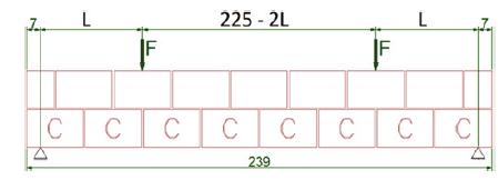
Length of 2,39m, with span between supports of 2,25m, according to Figure [10];
-
Beam block (14x19x29cm) in the first course and regular blocks (14x19x29cm) in the second course, fully grouted, as Figure [9];
-
Amount of shear reinforcement (2 cases): 1∅5,0c/15 or 1∅6,3c/15 (one-leg stirrups);
-
Amount of flexural reinforcement (1 case): 2∅ 10,0 mm + 2∅ 16,0 mm;
-
Resistance of the materials according to Table [2].
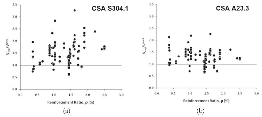
Comparison between the value of the experimental and theoretical shear force ratio (Y-axis) and the longitudinal reinforcement rate (X-axis) according to the Canadian Masonry Standard (a) and the Canadian Concrete Standard (b)
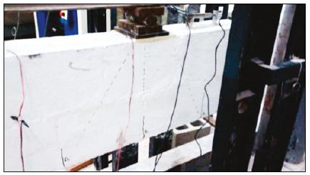
The longitudinal reinforcement used, approximately 4.8 cm², was determined to induce shear failure, that is, with this quantity the beam has a higher flexural strength than the shear strength. The shear reinforcement was constituted of one-leg stirrups, every 15 cm, with bars of 5.0 mm (1.31cm² / m) or 6.3 mm (2.08 cm² / m), according to each case. The loading was applied in pairs of equidistant loads and the position of these loads in relation to the supports was variable, as: type 1, with loads to 82,5 cm of the support; type 2, with loads 52.5 cm from the support; type 3, with loads 22.5 cm from the support), according to Figure [10]. The nomenclature for each beam was defined by following sequence of characters: V (indicates Beam, “Viga” in Portuguese), loading position (1, 2 or 3), approximate diameter of the stirrup (5 or 6 mm), beam specimen tested (two beams tested for each combination, first as A, the second as B). For example, beam V35B, indicated load type 3 (load 22.5 cm from bearing), stirrup 5.0 mm every 15 cm, and the second beam tested (B). Figure [12] shows a beam before the test.
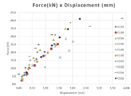
Figure [13] shows the typical instrumentation of each test. In figure [14[14] Parsekian, G. A., Hamid, A. A. e Drysdale, R. G. Comportamento e Dimensionamento de Alvenaria Estrutural, 1ª Edição, São Carlos, EdUFSCar, 2012. 625p.] the force vs central displacement curve of the beams is presented. It can be observed that the beams indicate a fragile behavior, like that shown in figure [3[3] AUSTRALIAN STANDARDS (AS) - AS 3700: Masonry Structures, Sydney, 2001.].
The load was applied with 5kN increments. For each increment, the displacements values at each transducer was recorded and the cracks in the beam were marked with hydrographic pen. The instrumentation was removed when a significant increase in the vertical joint’s cracks was observed. After the instrumentation was removed, the test continued until the bursting load was reached. Among the ten beams, it was not possible to reach the failure load for the V35B beam, due to limitations in the equipment used in the tests. For this reason, the V35B beam will not be analyzed for its failure load and, consequently, the type of rupture found.
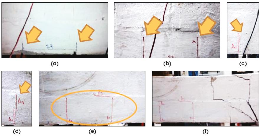
5.1 Beam cracking
It was possible to observe that all the beams followed the same cracking pattern and their behavior is consistent with the truss analogy. Figure [14] illustrates typical cracking. The first occurred at the mortar joint, as observed by other authors, such as Landini (2001), according to (a) and (b). The reason for these cracks to start at the mortars joints is because these joints are the weak point in the flexural strength due to the low adhesion in the block-mortar-block system. In Figure [15] (c) and (d) it is possible to observe the growth of the existing cracks and the appearance of others. With the growth of the crack in the vertical joint this tends to walk through the horizontal joint towards the load point of application, as (e) and (f). After the development of the cracks in the horizontal direction, the rupture is imminent.
In reinforced concrete beam analyses Fusco (2008) indicates that in the region close to the supports the cracks are distributed in the form of a “fan-shape”, which also occurs at the points of application of concentrated load, as shown in Figure [16]. In the masonry beams it was possible to observe the appearance of this fan-shape-like range of cracks, according to Figure [14], since the beginning of the cracks occurred below the point of application of the load starting from the lower edge of the beam toward the concentrated force.
5.2 Failure load and comparison with codes specifications
Table [3] indicates the results of the tests and the shear strength prediction according to each code specification indicated in part 4. In this calculation none material reduction factor or load factor no was considered, ie, these coefficients were taken equal to 1.0. The prism resistance was taken from the average value obtained in the tests, and this same value is considered as a substitute of the concrete strength in the case of NBR 6118. For the NBR 15961 and Eurocode standards, which allow an increase in the predicted rupture load as a function of M ⁄ (V ∙ d), with no upper limit, loads were calculated considering or not this increase. The TMS 402 also allows an increase, but imposes an upper limit, then it was considered the value calculated by this standard without changes.
In Table [4] the tests result and the standard predictions are compared. Highlighted in red are the values with a difference of more than 10% above the test result. In green, values ranging from 90% to 110% of the test result are considered. In yellow, values less than 90% of the test result are noted.
From the result is is possible to point out that considering the ratio M ⁄ (V ∙ d) to increase the shear strength leads to unconservative values, as possible to observe in the NBR and Eurocode results (almost all red values) and even in the TMS results (3 red values). Thus, to consider of the ratio M ⁄ (V ∙ d) as a linear increase factor in the analyses is not recommended. On the other hand, when we disregarded M ⁄ (V ∙ d), all values calculated by NBR 15961 resulted in conservatives (yellow), with half of the Eurocode values being conservative (yellow) and half accurate (green). It should be noted that the difference between those two codes specification is only the steel strength specification, being indicated 0,5 ∙ fyk for NBR and 0,9 ∙ fyk for Eurocode. From the results, it is debatable and probably unnecessary to consider the tension in the steel reduced by 50%. These observations are also present in Pasquantonio et al. (2016) where results from more than a hundred tests are evaluated.
If the concrete standard NBR 6118 is applied directly, two cases are accurate and the other conservatives. It is worth noting that the resistance of the prism was considered instead of fck which is probably the explanation for the conservative values. It is worth mentioning that this substitution was performed because in the calculations of other structural elements such as walls, the compressive strength value of the prisms is used.
The application of the Canadian and Australian standard, CSA 304 and AS 3700, leads to almost all accurate results, with little conservative values, and no value above 10% of the test results. The difference between the Australian and Brazilian standard again is the steel strength considered in the calculation, and AS 3700 allows 100% of the steel strength, above the 50%-strength of the Brazilian standard and 90%-strength of the European standard. This consideration of the Australian standard led to a greater number of accurate results. In the case of the Canadian standard, the steel stress is also considered to be 100% of the steel strength, in addition to an increase in the value of the shear resisted by the reinforcement when considering the angle of the compressed strut equal to 42°. Also, in the case of the Canadian standard, the shear strength of the masonry is taken as a function of the square root of the resistance of the prism, while the Brazilian standard, as well as the Australian and European standards, simplify admit a fixed strength value of 0.35 MPa.
All international standards impose an upper limit for shear strength due to the compressive strength of the masonry. This limitation is not present in NBR 15961 specifications.
6. Analysis and recommendation to the Brazilian code
Some factors are taken into account in the calculation of the maximum shear strength resisted by a reinforced masonry section: the shear strength, the longitudinal reinforcement (dowel action), the ratio M ⁄ (V ∙ d) (concentration of the vertical force close to the support), the design strength considered for stirrups steel, the limit of resistance in relation to the compressive strength of the masonry. In this item we analyze each of these factors, recommending specification for Brazilian code. Also, the considerations on minimum reinforcement area are verified. In the end, the recommendation to the test results, including or not the resistance and stress enhancement coefficients, is compared, as a way of ascertaining these recommendations in a simplified way.
6.1 Masonry shear strength
Some standards consider shear strength as a function of the square root of the compressive strength (TMS, CSA), while the Brazilian standard for concrete NBR 6118 consider it as a function of the cubic root of the compressive strength. Other (NBR 15961, Eurocode, AS) indicate an absolute value, equal to 0, 35 MPa for this resistance. As indicated in Parsekian (2012), the value of 0.35 MPa is equivalent to considering the compressive strength approximately equal to 15 MPa as the specifications of NBR 6118, which is the minimum resistance of the grout. By CSA S304, this resistance is equal to 18% of the root of the prism strength. From the TMS code specifications, if we considered the value of M ⁄ (V ∙ d) equal to 1.0 (minimum value), the specification is similar, equal to 18.7% of the root of the prism strength. To obtain the value of 0.35 MPa, a prism strength equal to 3.8 MPa is required. Considering that the section is fully grouted, this prism value is obtained even with low-strength 4.0- MPa blocks. Therefore, the resistance value considered as 0.35 MPa, is a lower limit, and it is recommended to keep this value in Brazilian normalization. This recommendation is simple, does not change the usual procedure, with only disadvantage of being conservative if higher-strength blocks and grouts are used.
6.2 Contribution of longitudinal reinforcement (dowel action)
This effect is considered in the NBR 15961-1/2011-1/2011, AS3700/2001 e Eurocode 6.1/2001. specification Nagato et al. (2003) confirms this effect in reinforced concrete beams but indicates that the reinforcement rate has no great influence. In all standards, the steel shear strength is 17.5 MPa. The Australian standard imposes an upper limit for the longitudinal reinforcement ratio in the consideration of the dowel action, equal to 2%, which in a way corroborates with the conclusions of Nagato et al. (2003) on the effect not to be directly proportional to the reinforcement rate, although it exists. The NBR 15961-1 / 2011-1 / 2011 indicates the maximum value of shear strength equal to 0.7 MPa, which corresponds to the reinforcement rate, equal to 2%, this already considering this same limit.
6.3 Relation M / (V ∙ d) (concentration of vertical forces close to the support)
Several authors acknowledge that applying a vertical load close to the support will cause it to be transferred directly to the support by the compression stresses, at least partially. In reinforced masonry beams, Suter and Keller (1976) confirm this effect, however limiting this ratio to 2.0. In the comparison with the results of the tests, the results of NBR 15961-1/2011-1/2011 and Eurocode 6.1/2001, which do not indicate an upper limit for this effect, were non-conservative. Even by TMS 402/2016, which indicates an upper limit, some verifications were non-conservative.
The Brazilian standard for concrete, NBR 6118, as well as the Australian standard AS 3700, allow to consider the value of the shear force at a distance “d” from the support face, taking into account the arching of the internal forces near the support.
Considering the reduction of the shear force by considering its value at a distance "d" from the support is indicated, replacing the consideration of M ⁄ (V ∙ d). As the shear diagram is constant close to the support, it was not possible to measure this effect in the tests, but this prescription is present in the Australian standard and NBR 6118.
6.4 Strength considered for the stirrup steel
The current specification at the NBR 15961-1/2011, of limiting the The current specification at the NBR 15961-1/2011, of limiting the steel strength to 50% of fyk, is also in TMS 402/2016. Eurocode 6.1/2001 and NBR 6118/2014 indicate that 0,9 ∙ fyk are considered for the stirrups, while AS3700/2001 and CSA S304/2014 indicate considering fyk directly. The results of the failure load from the AS3700/2001 and CSA S304/2014 standards specifications were close to the tests results. Considering these evaluations, it is understood that considering the steel stress 0,9 ∙ fyk, is suitable for NBR 15961-1/2011.
6.5 Strength limit in relation to the compressive strength of masonry
NBR 15961 is the only standard that does not indicate a limit to the masonry compression strut strength. Therefore, it is understood to be important to include this limit. The AS3700/2001 recommendation is simple, basically indicating the maximum resistance equal to 1,4 MPa (4 ∙ 0,35 MPa). The prescription of CSA S304/2014 and TMS 402/2016 considers the prism strength, which is more suitable for this verification. Thus the recommendation is to limit the shear force to the limit indicated in the CSA S304/2014, equal to or , substituting ϕm for 1 ⁄ γm . It should be noted that the CSA S304/2014resistance reduction coefficient is greater than 1 ⁄ γm indicated by NBR 15961, so the Brazilian specification will be more conservative.
6.6 Minimum reinforcement
According to TMS 402/2016 one must always consider a minimum reinforcement for beams with more than one course. Considering the shear brittle failure, it is considered appropriate to follow this recommendation. For la one-course lintel, common in constructions, one can admit the non-use of stirrups, calculating the shear strength appropriately. The minimum reinforcement area is considered equal to 0,07%bs in several masonry standards. Comparing this value with that specified by NBR 6118/2014, , for vertical stirrups, with fctm = 0,3 fck 2/3, we reach the minimum area of 0,0073 ∙ b ∙ s when considering fck equivalent to a minimum of resistance C15, therefore equivalent to that found in some masonry standards. It is therefore suggested to adopt this value as minimum armor equal to 0,0073 ∙ b ∙ s.
6.7 Comparison with test results
Table [5] shows the comparison of the above proposal with the results of the tests. All results are lower than the test results, with four "green" cases considered to be accurate. Considering the coefficients of γalv = 2,00, γs = 1,15 and γf = 1,40, the calculation values of maximum shear force are at least 1.9 times the results of the tests.
7. Conclusion
As for the experimental analysis it was possible to conclude based on the tests that:
-
The rupture pattern is like that expected for reinforced concrete beams;
-
The cracks were conditioned by the position of the loading application point and by the mortar joints;
-
The increase in the transverse reinforcement ratio led to the increase of the shearing force of rupture.
Regarding the recommendations for Brazilian standard NBR15961-1 / 2011, it can be concluded that:
-
With respect to the shear strength, it is suggested to maintain the value of 0,35MPa;
-
In relation to the contribution of longitudinal reinforcement, the recommendation of NBR15961, is consistent with the specifications of other international standards, including the reinforcement rate limit of 2%. The maximum value to the shear strength allowed by this code is equivalent to considering this reinforcement rate. Referring to the ration M ⁄ (V ∙ d), it is recommended to withdraw the existing prescription in NBR15961 and to consider the value of the maximum shear force at a distance “d” from the support taking into account the arching of the internal forces near of the support, which is the same prescription as in NBR6118/2014;
-
As for the steel transverse reinforcement strength, it is recommended to use the yield stress of the steel equal to 0.90 of the characteristic tension of the steel;
-
As the current NBR15961 does not prescribe any calculation to verify the maximum compression strut strength near to the support, it is recommended to use the equation prescribed in CSA S304/2014;
-
In relation to the minimum armature value, it is recommended to use the equation Asw,min = 0,0073 ∙ b ∙ s.
Considering all the recommendations presented here, we estimate the maximum shear value between 73% and 106% of the results obtained in the tests. Considering the materials and load safety factors as in NBR15961, the results of maximum shear values were at least 1.9 times greater than the tests results.
8. References
-
[1]ASSOCIAÇÃO BRASILEIRA DE NORMAS TÉCNICAS (ABNT). NBR 15961-1 Alvenaria Estrutural - Blocos de Concreto - Parte 1: Projeto., Rio de Janeiro 2011.
-
[2]ASSOCIAÇÃO BRASILEIRA DE NORMAS TÉCNICAS (ABNT). NBR 6118: Projeto de Estruturas de Concreto - Procedimento., Rio de Janeiro 2007
-
[3]AUSTRALIAN STANDARDS (AS) - AS 3700: Masonry Structures, Sydney, 2001.
-
[4]Camacho, J. S. Projeto de Edificios de Alvenaria Estrutural, 1ª Edição, Ilha Solteira, Nepae, 2006, 48p.
-
[5]CANADIAN STANDARDS ASSOCIATION (CSA). S304-14: Design Masonry Strutuctures, Ontario, 2014
-
[6]European Stanadard (EN), Eurocode 6: Design of Masonry Structures - Part 1-1: Common rules for reinforced and unreinforced masonry structures, Londres, 2001
-
[7]Fereig, S. M. Shear Strength of Reinforced Concrete Masonry Beams with Web Reinforcement, In: Technical Paper, 8, 1994, Michigan, ACI Structural Journal, Michigan, 1994.
-
[8]Fusco, P. B. Estruturas de Concreto: Solicitações Tangenciais, 1ª Edição, São Paulo, Pini, 2008. 328p
-
[9]Fusco, P. B. Técnica de Armar Estruturas de Concreto, 1ª Edição, São Paulo, Pini, 1995. 382p
-
[10]Guzman, M.J. e Lissel, S.L. The Source of Canadian Design Standard Requirements for Shear Design in Beams, In: THE TENTH CANADIAN MASONRY SYMPOSYUM, 2c-3, 2005, Banff, Proceedings The Tenth Canadian Masonry Symposium, Banff: CMS, 2005
-
[11]Landini, F.S. Comportamento à Flexão e ao Esforço Cortante de Vigas em Alvenaria Estrutural. 2001. 135p. Dissertação (Mestrado). Faculdade Engenharia Civil - Universidade Estadual de Campinas (UNICAMP) - SP, 2001.
-
[12]Mörsch, E. Teoría y Práctica del Hormigón Armado, volume 2. Trad Espanhola, Gustavo Gilli, Barcelona, 1948.
-
[13]Nagato, Y.; Melo, G.S.S.A.; Oliveira, A.A.S. Um Estudo sobre o Efeito de Pino da Armadura Longitudinal de Vigas de CA. Anais do V Simpósio EPUSP sobre Estruturas de Concreto. São Paulo, Universidade de São Paulo, 2003.
-
[14]Parsekian, G. A., Hamid, A. A. e Drysdale, R. G. Comportamento e Dimensionamento de Alvenaria Estrutural, 1ª Edição, São Carlos, EdUFSCar, 2012. 625p.
-
[15]Pasquantonio, R.D., Análise Teórica e Experimental de Vigas de Alvenaria Estrutural Sujeitas ao Cisalhamento. 2015. 176p. Dissertação (Mestrado). Programa de Pós-Graduação em Gestão e Construção Civil, Universidade Federal de São Carlos, SP, 2015.
-
[16]Pasquantonio, R. D.; Parsekian, G. A.; Soudais, P. R. N.; Camacho, J. S. Shear strength of concrete block beams: Assessment of international codes and influence of shear span and longitudinal reinforcement. In: 16th International Brick and Block Masonry Conference, 2016, Padova. 16th International Brick and Block Masonry Conference. Londres: CRC Press, 2016. v. 1. p. 1789-1797.
-
[17]Ring T.; Das S. e Stubbs D. Compressive Strength of Concrete Masonry Beams, In: TECHNICAL PAPER, 109-S31, 2012, Michigan. ACI Structural Journal, Michigan: ACI, 2012.
-
[18]Sarhat, S.R. e Sherwood, E.G. Shear Design of Reinforced Masonry Beams. In: THE ELEVENTH NORTH AMERICAN MASONRY CONFERENCE, 3.04-2, 2011, Minneapolis, Proceedings of The Eleventh North American Masonry Conference, Minneapolis: University de Minnesota, 2011.
-
[19]Sarhat, S.R. e Sherwood, E.G. Effective Shear Design Reinforced Masonry Beams. In: ANNUAL CONFERENCE OF THE CANADIAN SOCIETY FOR CIVIL ENGINEERING, v-2, 2010, Ottawa, Proceedings, Annual Conference - Canadian Society for Civil Engineering, Ottawa: University of Carleton, 2007.
-
[20]Suter, G.T e Keller, H. Shear Strength of Reinforced Masonry Beams and Canadian Code Implications, 1976, p149-160, National Research Concil, 1976
-
[21]THE MASONRY SOCIETY (TMS) - TMS 402 Building Code Requirements for Masonry Structures. Longmont, Colorado, 2016.
-
[22]Zohrehheydariha, J.; Das, S.; Banting, B. Behaviour Of Stack Pattern Masonry Beams. Proceedings of The Thirteenth Canadian Masonry Symposium, Halifax, Dalhousie University, 2017.
Publication Dates
-
Publication in this collection
23 Sept 2019 -
Date of issue
Jul-Aug 2019
History
-
Received
27 Oct 2016 -
Accepted
18 Aug 2017 -
Published
08 Aug 2019

 Source: Fusco (2008)
 Source: Fusco (2008)
 Source: Neis and Loefller (1983)
 Source: Fusco (2008)
 Source: Suter and Keller (1976)
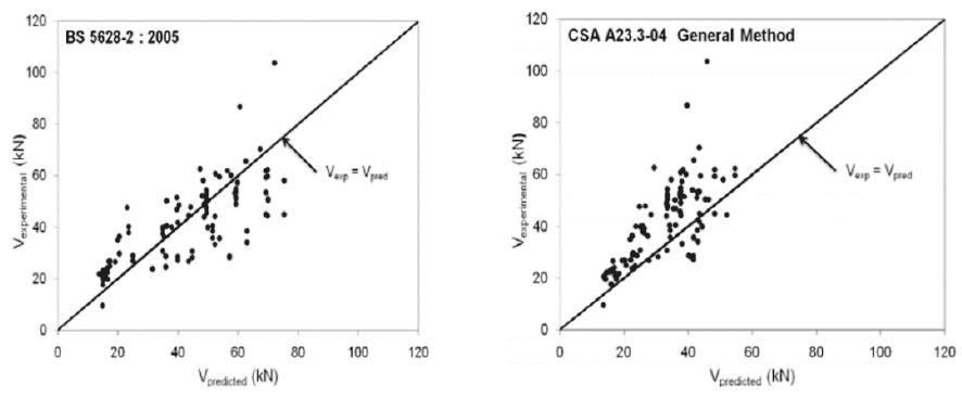 Source: Sarhat and Sherwood (2007)
 Source: Sarhat and Sherwood (2007)
 Source: Pasquantonio (2015)
 Source: Pasquantonio (2015)
 Source: Pasquantonio (2015)
 Source: Pasquantonio (2015)
 Source: Pasquantonio (2015)
 Source: Pasquantonio (2015)
 Source: Pasquantonio (2015)
 Source: Pasquantonio (2015)
 Source: Pasquantonio (2015)