abstract:
Concrete with recycled aggregate is a fragile material under tensile stresses. However, like conventional concrete, it is possible that its contribution is relevant in the design of reinforced concrete elements under tension or bending, even after cracking. The objective of this work is to evaluate the application of the analytical models used to predict the effect of tension stiffening on recycled reinforced concrete. Tests of reinforced concrete under tensile were performed using conventional concrete and concrete containing 25% and 50% replacement of the natural aggregate with recycled aggregate. From the experimental results of reinforced concrete, the contribution of the concrete was isolated and a parametric study was carried out to identify which analytical model in the literature may be more appropriate. The models proposed by Carreira and Chu (1986), Vecchio and Collins (1986) and Hsu and Mo (2010) were evaluated. A numerical analysis, based on the finite element method, was implemented to model the mechanical behavior of the reinforced concrete under tensile using the analytical models already adjusted to concrete with recycled aggregate. The stress distribution in steel and concrete and the cracking mode were evaluated numerically. The results indicate that the parameters used in the analytical models for conventional concrete cannot predict the behavior of concrete with recycled aggregate and need to be modified to obtain a more accurate answer.
Keywords:
tension stiffening; damage; plasticity; finite elements
resumo:
O concreto com agregado reciclado é um material frágil sob tensões de tração, no entanto, assim como o concreto convencional, é possível que, mesmo após sua fissuração, a sua contribuição seja relevante no dimensionamento de elementos de concreto armado sob tração ou flexão. O objetivo deste trabalho é avaliar a aplicação dos modelos analíticos usados na previsão do efeito do enrijecimento a tração (tension stiffening) ao concreto armado reciclado. Ensaios de tirantes de concreto armado foram realizados utilizando concreto convencional e concreto contendo 25% e 50% de substituição do agregado natural por agregado reciclado. A partir dos resultados experimentais, a contribuição do concreto foi isolada e um estudo paramétrico foi realizado para identificar qual modelo analítico existente na literatura pode ser mais apropriado. Foram avaliados os modelos propostos por Carreira e Chu (1986), Vecchio e Collins (1986) e Hsu e Mo (2010). Uma análise numérica baseada no método dos elementos finitos foi implementada para modelar o comportamento mecânico do tirante de concreto armado utilizando os modelos analíticos já ajustados ao concreto com agregado reciclado. A distribuição de tensões no aço e no concreto e o modo de fissuração foram avaliados numericamente. Os resultados indicam que os parâmetros utilizados nos modelos analíticos para concreto convencional não conseguem prever o comportamento do concreto com agregado reciclado e precisam ser modificados para se obter uma resposta mais precisa.
Palavras-chave:
tirante de concreto armado; modelo de dano; plasticidade; método dos elementos finitos
1 INTRODUCTION
The great success obtained by reinforced concrete as a structural material is due to the excellent bond between the reinforcement and the concrete, which allows the redistribution of stresses between the materials after the cracking of the concrete. Due to this bond, the concrete, considered as a fragile material under tensile stress, can contribute to the increase of the strength and stiffness of the reinforced concrete even after the formation of cracks, in an effect called “tension stiffening”. The tension stiffening effect has been defined as the contribution of intact concrete between cracks to the stiffness of the structural element or even by the ability of intact concrete between cracks to resist part of the resulting tensile forces. This contribution of cracked concrete has been identified as responsible for increasing the flexural strength [11 Comité Euro-International du Béton, Design Manual on Cracking and Deformation (Bulletin d’Information 158). 1985.], increasing the shear strength of reinforced concrete structures [22 F. J. Vecchio and M. P. Collins, "The modified compression-field theory for reinforced concrete elements subjected to shear," ACI J. Proc., vol. 83, no. 2, pp. 219–231, Oct 1986.], increasing the stiffness of reinforced concrete slabs [33 R. Ian Gilbert, "Tension stiffening in lightly reinforced concrete slabs," J. Struct. Eng., vol. 133, no. 6, pp. 899–903, Jun 2007, http://dx.doi.org/10.1061/(ASCE)0733-9445(2007)133:6(899).
http://dx.doi.org/10.1061/(ASCE)0733-944...
] and for the non-linear response of reinforced concrete under stress [44 S. Khalfallah and D. Guerdouh, "Tension stiffening approach in concrete of tensioned members," Int. J. Adv. Struct. Eng., vol. 6, no. 1, pp. 1–6, Jan 2014, http://dx.doi.org/10.1007/s40091-014-0051-8.
http://dx.doi.org/10.1007/s40091-014-005...
].
Due to the importance of this phenomenon, several studies have been carried out to determine theoretical models of the tension stiffening effect, as a way of incorporating it into the design standards for reinforced concrete structures. In this context, two different approaches have been used to determine the constitutive models: i) change in the constitutive equation associated with steel [11 Comité Euro-International du Béton, Design Manual on Cracking and Deformation (Bulletin d’Information 158). 1985.], [55 R. Ian Gilbert and R. F. Warner, "Tension stiffening in reinforced concrete slabs," J. Struct. Div., vol. 104, no. 2, pp. 1885–1900, 1978.], [66 C. K. Choi and S. H. Cheung, "Tension stiffening model for planar reinforced concrete members," Comput. Struc., vol. 59, no. 1, pp. 179–190, Apr 1996, http://dx.doi.org/10.1016/0045-7949(95)00146-8.
http://dx.doi.org/10.1016/0045-7949(95)0...
]; ii) or modification of the constitutive law of concrete, after the opening of the first crack [22 F. J. Vecchio and M. P. Collins, "The modified compression-field theory for reinforced concrete elements subjected to shear," ACI J. Proc., vol. 83, no. 2, pp. 219–231, Oct 1986.], [77 A. Scanlon and D. Murray, "Time-dependent reinforced concrete slab deflections," J. Struct. Div., vol. 100, no. 8, pp. 1911–1924, Sep 1974.], [8]8 A. K. Gupta and S. R. Maestrini, "Tension-stiffness model for reinforced concrete bars," J. Struct. Eng., vol. 116, no. 3, pp. 769–790, Mar 1990, http://dx.doi.org/10.1061/(ASCE)0733-9445(1990)116:3(769).
http://dx.doi.org/10.1061/(ASCE)0733-944...
. Despite the good results obtained with the theoretical models for determining the tension stiffening effect, the parameters obtained for the design have been validated through experimental results of conventional reinforced concrete elements, which may limit its applicability to structures produced with recycled concrete aggregate.
The use of concrete with recycled aggregate in reinforced concrete structures is allowed by several design standards [99 P. C. M. Gonçalves, “Betão com agregados reciclados – análise comentada da legislação existente,” M.S. thesis, Inst. Sup. Téc., UTL, Lisboa, 2007.] and, as a result, some studies [1010 J. Xiao, Y. Sun, and H. Falkner, "Seismic performance of frame structures with recycled aggregate concrete," Eng. Struct., vol. 28, no. 1, pp. 1–8, Jan 2006, http://dx.doi.org/10.1016/j.engstruct.2005.06.019.
http://dx.doi.org/10.1016/j.engstruct.20...
], [1111 V. Corinaldesi, V. Letelier, and G. Moriconi, "Behaviour of beam-column joints made of recycled-aggregate concrete under cyclic loading," Constr. Build. Mater., vol. 25, no. 4, pp. 1877–1882, Apr 2011, http://dx.doi.org/10.1016/j.conbuildmat.2010.11.072.
http://dx.doi.org/10.1016/j.conbuildmat....
] and practical applications [1212 J. Xiao, W. Li, Y. Fan, and X. Huang, "An overview of study on recycled aggregate concrete in China (1996–2011)," Constr. Build. Mater., vol. 31, pp. 364–383, Jun 2012, http://dx.doi.org/10.1016/j.conbuildmat.2011.12.074.
http://dx.doi.org/10.1016/j.conbuildmat....
] have reported the inherent gains in economic or sustainability terms of this material. However, the cracking mode of recycled concrete is different from conventional concrete, either under tensile [1313 C. S. Rangel, M. Amario, M. Pepe, Y. Yao, B. Mobasher, and R. D. Toledo Fo., "Tension stiffening approach for interface characterization in recycled aggregate concrete," Cement Concr. Compos., vol. 82, pp. 176–189, Sep 2017., http://dx.doi.org/10.1016/j.cemconcomp.2017.06.009.
http://dx.doi.org/10.1016/j.cemconcomp.2...
] or compression [1414 J. A. Carneiro, P. R. L. Lima, M. B. Leite, and R. D. Toledo Filho, "Compressive stress–strain behavior of steel fiber reinforced-recycled aggregate concrete," Cement Concr. Compos., vol. 46, pp. 65–72, Feb 2014, http://dx.doi.org/10.1016/j.cemconcomp.2013.11.006.
http://dx.doi.org/10.1016/j.cemconcomp.2...
] stresses, due to the lower strength and stiffness of the recycled aggregate, which may limit the use of some established and validated standard equations for conventional concrete.
The structural behavior evaluation of reinforced concrete beams with recycled aggregates, carried out by Etxeberria et al. [1515 M. Etxeberria, A. R. Marí, and E. Vázquez, "Recycled aggregate concrete as structural material," Mater. Struct., vol. 40, no. 5, pp. 529–541, Jun 2007, http://dx.doi.org/10.1617/s11527-006-9161-5.
http://dx.doi.org/10.1617/s11527-006-916...
], identified that the design standards overestimate the shear strength of reinforced concrete beams produced with recycled aggregate. According to Ignjatović et al. [1616 I. S. Ignjatović, S. B. Marinković, Z. M. Mišković, and A. R. Savić, "Flexural behavior of reinforced recycled aggregate concrete beams under short-term loading," Mater. Struct., vol. 46, no. 6, pp. 1045–1059, Jun 2013, http://dx.doi.org/10.1617/s11527-012-9952-9.
http://dx.doi.org/10.1617/s11527-012-995...
], the deflection in service of reinforced concrete beams containing recycled aggregate may be higher than the deflection of beams with conventional reinforced concrete. Xiao et al. [1010 J. Xiao, Y. Sun, and H. Falkner, "Seismic performance of frame structures with recycled aggregate concrete," Eng. Struct., vol. 28, no. 1, pp. 1–8, Jan 2006, http://dx.doi.org/10.1016/j.engstruct.2005.06.019.
http://dx.doi.org/10.1016/j.engstruct.20...
] evaluated the bond between steel bars and recycled concrete and, after verifying the reduction in bond with the increase of the content of recycled aggregate in the concrete, established a new empirical law to determine the steel-recycled concrete bond. The drying shrinkage measures of concrete with recycled aggregate also indicate that the equations currently used by the structural design standards cannot predict the shrinkage behavior of recycled concrete [1717 R. V. Silva, J. Brito, and R. K. Dhir, "Prediction of the shrinkage behavior of recycled aggregate concrete: a review," Constr. Build. Mater., vol. 77, pp. 327–339, Feb 2015, http://dx.doi.org/10.1016/j.conbuildmat.2014.12.102.
http://dx.doi.org/10.1016/j.conbuildmat....
]. Considering all these aspects and the important effect that drying shrinkage has on the tension stiffening effect of concrete [1818 P. H. Bischoff, "Effects of shrinkage on tension stiffening and cracking in reinforced concrete," Can. J. Civ. Eng., vol. 28, no. 3, pp. 363–374, 2001., http://dx.doi.org/10.1139/l00-117.
http://dx.doi.org/10.1139/l00-117...
], [1919 G. Kaklauskas, V. Gribniak, D. Bacinskas, and P. Vainiunas, "Shrinkage influence on tension stiffening in concrete members," Eng. Struct., vol. 31, no. 6, pp. 1305–1312, Jun 2009, http://dx.doi.org/10.1016/j.engstruct.2008.10.007.
http://dx.doi.org/10.1016/j.engstruct.20...
], it is believed that the use of normative models of the tension stiffening effect, calibrated for conventional concrete [2020 S. M. Allam, M. S. Shoukry, G. E. Rashad, and A. S. Hassan, "Evaluation of tension stiffening effect on the crack width calculation of flexural RC members," Alex. Eng. J., vol. 52, no. 2, pp. 163–173, Jun 2013, http://dx.doi.org/10.1016/j.aej.2012.12.005.
http://dx.doi.org/10.1016/j.aej.2012.12....
], are not valid for recycled reinforced concrete. Due to such particularities of recycled concrete, Kosior-Kazberuk and Grzywa [2121 M. Kosior-Kazberuk and M. Grzywa, "Recycled aggregate concrete as material for reinforced concrete structures," J. Sustain. Archit. Civ. Eng., vol. 7, no. 2, pp. 60–66, Jun 2014, http://dx.doi.org/10.5755/j01.sace.7.2.7135.
http://dx.doi.org/10.5755/j01.sace.7.2.7...
] indicate that the special properties of concrete with recycled aggregate need to be considered in the design of reinforced concrete structures.
The objective of this work is to evaluate the tension stiffening effect of recycled concrete on the mechanical behavior of elements of reinforced concrete under tensile stress. For this, changes were made to the theoretical tension stiffening models proposed by Carreira and Chu [2222 D. J. Carreira and K. H. Chu, "Stress-strain relationship for reinforced concrete in tension," ACI J., vol. 83, no. 1, pp. 21–28, Jan 1986.], Vecchio and Collins [22 F. J. Vecchio and M. P. Collins, "The modified compression-field theory for reinforced concrete elements subjected to shear," ACI J. Proc., vol. 83, no. 2, pp. 219–231, Oct 1986.] and Hsu and Mo [2323 T. T. C. Hsu and Y. L. Mo, Unified Theory of Concrete Structures. Chichester, UK: Wiley, 2010.] to fit the experimental results of concrete containing 0%, 25% and 50% of recycled aggregate. Subsequently, the elements were numerically modeled, using the finite element method, to evaluate the most appropriate theoretical model for the design of recycled concrete elements. The cracking pattern of the elements and the level of stress in the concrete and in the reinforcement were also numerically obtained and discussed.
2 ANALYTICAL MODELS OF THE TENSION STIFFENING EFFECT
The tension stiffening effect can be seen in Figure 1a, in which an element is subjected to tensile stress. The typical curve of this element subjected to tensile can be subdivided into 3 phases.

Stages of typical load-strain behavior of a tension stiffening element (a) and region where new cracks appear (b).
The first phase is represented by the elastic region, where the stresses and strains of the element follow the Hooke’s Law, and there are no cracks in the concrete. The second phase is initiated by the primary cracking of the concrete and the appearance of new cracks, as the stresses in the concrete (between cracks already formed) reach the tensile strength of the concrete. Thus, phase 2 is marked by instability in the test due to gradual cracking. At the end of phase 2, all the cracks have already appeared and a reduction in the stiffness of the element is verified. At the crack opening site, the force is resisted almost exclusively by the steel bar, while in the region between cracks some tensile force is transferred (by bond) from the bar to the surrounding concrete, which results in a reduction of stresses and deformations in the reinforcement. At the beginning of cracking, the tension stiffening effect reaches its maximum value (see Figure 1b) and gradually decreases with the evolution of the deformation. In the third phase, there is a stable cracking, with the opening of existing cracks and loss of bond between steel and concrete. In this phase, the contribution of concrete between cracks is reduced to zero as the reinforcement steel tends to yielding phase.
The prescription of the load-displacement behavior of reinforced concrete elements can be performed by standard specifications such as CEB [11 Comité Euro-International du Béton, Design Manual on Cracking and Deformation (Bulletin d’Information 158). 1985.]. To determine the tension stiffening effect, several models have been proposed over the years, being differentiated by the complexity and number of variables involved in the equations. In this study, the constitutive equations proposed by Carreira and Chu [2222 D. J. Carreira and K. H. Chu, "Stress-strain relationship for reinforced concrete in tension," ACI J., vol. 83, no. 1, pp. 21–28, Jan 1986.], Vecchio and Collins [22 F. J. Vecchio and M. P. Collins, "The modified compression-field theory for reinforced concrete elements subjected to shear," ACI J. Proc., vol. 83, no. 2, pp. 219–231, Oct 1986.] and Hsu and Mo [2323 T. T. C. Hsu and Y. L. Mo, Unified Theory of Concrete Structures. Chichester, UK: Wiley, 2010.] were used, which were based on experimental studies and used in different applications.
2.1 Tension stiffening Model by CEB [11 Comité Euro-International du Béton, Design Manual on Cracking and Deformation (Bulletin d’Information 158). 1985.]
A classic model for evaluated the behavior of reinforced concrete elements is presented by CEB [11 Comité Euro-International du Béton, Design Manual on Cracking and Deformation (Bulletin d’Information 158). 1985.], as illustrated in Figure 2.

In this model, the objective is to determine the average relative deformation of the reinforcement εsm of an element of length L subjected to an axial load N. Until reaching the total elongation ΔL, the element goes through an elastic phase (Phase 1 in Figure 1a) until reaching the crack load Nr. For values greater than Nr, the average strain of the reinforcement is given by:
Where represents the contribution of the concrete between cracks (tension stiffening effect), which was established experimentally as:
By substituting Equation 2 in Equation 1, it is obtained:
That can be written in the form:
Where ζ is a distribution coefficient given by:
In the Equation 1 to Equation 5, is the stress of the reinforcement in a cracked section; is stress in the reinforcement at the moment of cracking, that is, when the stress in the concrete reaches the tensile strength; is the deformation in the reinforcement in Phase 1; is the deformation in the reinforcement after cracking the concrete, not considering the contribution of the concrete between cracks; is the strain in the reinforcement corresponding to the stress , in Phase 1; is the strain in the reinforcement corresponding to the stress , not considering the contribution of concrete between cracks.
To consider the quality of the bond of the reinforcement bars and the influence of the duration and repetition of the load application, the CEB Model Code 1990 [2424 Comité Euro-International du Béton. Fédération Internationale de la Précontrainte, CEB-FIP Model Code 1990: Design Code, 1993.] introduced, respectively, the coefficient β1 and the coefficient β2 in Equation 5:
Where , with for ribbed bars and for smooth bars, and for load applied for a short time and for load applied for a long time or for a large number of load cycles.
2.2 Model by Carreira and Chu [2222 D. J. Carreira and K. H. Chu, "Stress-strain relationship for reinforced concrete in tension," ACI J., vol. 83, no. 1, pp. 21–28, Jan 1986.]
The equation proposed by Carreira and Chu [2222 D. J. Carreira and K. H. Chu, "Stress-strain relationship for reinforced concrete in tension," ACI J., vol. 83, no. 1, pp. 21–28, Jan 1986.] was adapted from a model for the behavior of concrete under compression and it is given by:
where and correspond, respectively, to the normal tensile stress and the specific linear strain in the stress-strain diagram; is the deformation corresponding to the maximum tensile stress. The parameter combines the effect of cracking and the loss of bond between the reinforcement and the concrete and it must be obtained from experimental tests.
Equation 7 was used by the authors [2222 D. J. Carreira and K. H. Chu, "Stress-strain relationship for reinforced concrete in tension," ACI J., vol. 83, no. 1, pp. 21–28, Jan 1986.] to determine the tension stiffening effect in concrete elements reinforced with different ratios of reinforcement, and values for ranging between 1.45 and 1.70 were adopted.
2.3 Model by Hsu and Mo [2323 T. T. C. Hsu and Y. L. Mo, Unified Theory of Concrete Structures. Chichester, UK: Wiley, 2010.]
The model presented by Hsu and Mo [2323 T. T. C. Hsu and Y. L. Mo, Unified Theory of Concrete Structures. Chichester, UK: Wiley, 2010.] was obtained based on experiments carried out on reinforced concrete panels submitted to uniaxial tensile stress. The equation that correlates the tensile stress in the concrete with the axial strain is given by:
Where the exponent μ is an adjustment parameter, initially adopted as equal to 0.4 by the authors [2121 M. Kosior-Kazberuk and M. Grzywa, "Recycled aggregate concrete as material for reinforced concrete structures," J. Sustain. Archit. Civ. Eng., vol. 7, no. 2, pp. 60–66, Jun 2014, http://dx.doi.org/10.5755/j01.sace.7.2.7135.
http://dx.doi.org/10.5755/j01.sace.7.2.7...
]; is the tensile strength of concrete and is the deformation corresponding to this stress, being adopted by Hsu and Mo [2323 T. T. C. Hsu and Y. L. Mo, Unified Theory of Concrete Structures. Chichester, UK: Wiley, 2010.] as , based on the experimental results for conventional concrete.
Equation 8 was used by Wang and Hsu [2525 T. Wang and T. T. C. Hsu, "Nonlinear finite element analysis of concrete structures using new constitutive models," Comput. Struc., vol. 79, no. 32, pp. 2781–2791, Dec 2001, http://dx.doi.org/10.1016/S0045-7949(01)00157-2.
http://dx.doi.org/10.1016/S0045-7949(01)...
] and by Dede and Ayvaz [2626 T. Dede and Y. Ayvaz, "Nonlinear analysis of reinforced concrete beam with/without tension stiffening effect," Mater. Des., vol. 30, no. 9, pp. 3846–3851, Oct 2009, http://dx.doi.org/10.1016/j.matdes.2009.02.003.
http://dx.doi.org/10.1016/j.matdes.2009....
], obtaining good results.
2.4 Model by Vecchio and Collins [22 F. J. Vecchio and M. P. Collins, "The modified compression-field theory for reinforced concrete elements subjected to shear," ACI J. Proc., vol. 83, no. 2, pp. 219–231, Oct 1986.]
The model proposed by Vecchio and Collins [22 F. J. Vecchio and M. P. Collins, "The modified compression-field theory for reinforced concrete elements subjected to shear," ACI J. Proc., vol. 83, no. 2, pp. 219–231, Oct 1986.] was based on the experiments carried out on reinforced concrete panels subjected to pure shear stress and it is given by:
Where η is an experimental parameter, adopted equal to 200 for conventional concrete, and is the tensile strain of the concrete in direction 1 (axial).
Equation 9 is present in the Modified Compression-Field Theory (MCFT) [22 F. J. Vecchio and M. P. Collins, "The modified compression-field theory for reinforced concrete elements subjected to shear," ACI J. Proc., vol. 83, no. 2, pp. 219–231, Oct 1986.], in which the authors reported the importance of considering the tension stiffening effect in the analysis of structures subjected to shearing force predominantly to flexion.
3 EXPERIMENTAL PROGRAM
3.1 Materials
The coarse recycled aggregate used in this study, with a maximum diameter of 9.5 mm, was obtained by demolishing concrete beams produced in laboratory for this purpose. The coarse natural aggregate was granite gravel with a maximum diameter of 9.5 mm. The water absorption test indicated that the natural aggregate has a total absorption of 1.2% while the recycled aggregate has a total absorption of 8.0%. Quartz sand with a maximum diameter of 4.75 mm, CPV-ARI cement and polycarboxylate-based superplasticizer with a solids content of 30% were used.
The concretes were composed according to the Compressible Packing Model (CPM), described in Rangel [2727 C. S. Rangel, “Influência de agregados graúdos reciclados nas propriedades estruturais de concretos de resistência normal e de alto desempenho,” M.S. thesis, Univ. Fed. Rio de Janeiro, Rio de Janeiro, 2015.], to achieve a compressive strength of 25 MPa and an slump value of 75 mm. Three types of concrete were produced, R0, R25 and R50, with the replacement of 0%, 25% and 50% of natural aggregate by recycled aggregate, respectively. Table 1 shows the consumption of materials for the production of the concrete mixtures, as well as the results of mechanical tests at 28 days after curing in a humid chamber. The superplasticizer content was about 3 kg/m3 for all mixtures. The concretes were produced in an air-conditioned room at 21ºC ± 1ºC, using a planetary mixer.
In the tension stiffening elements, CA 50 steel bars with 20 mm of diameter were used, which were subjected to tensile test and the bars presented a yield stress of 540 MPa, a rupture stress of 705 MPa and an elastic modulus of 232.9 GPa. This diameter bar was adopted so that a larger post-cracking region could be investigated before the bar begins the yielding phase.
3.2 Tension stiffening test
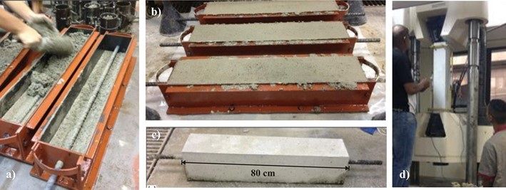
Metallic molds with dimensions of 15 x 15 x 80 cm were used to produce the tension stiffening elements. The steel bar was positioned in the center of the cross section of the mold before casting the concrete, as shown in Figure 3.

Production and tension stiffening test: a) casting of concrete; b) end of molding; c) test specimen; d) positioning the testing machine.
The tests were performed in a servo-controlled press with a capacity of 1000 kN, in three samples for each concrete mixture. The loading of the test was applied continuously, with a constant speed of 0.3 mm/min. Two electric transducers (LVDT) were used to measure longitudinal displacements in the central region of the specimens (0.7 m).
4 CALIBRATION OF ANALYTICAL MODELS
From the experimental result of the tension stiffening test, the contribution of the matrix to the overall load-strain behavior of the element was isolated. For this, it was evaluated the difference between the result obtained for the element and the individually contribution of the steel bar.
The analytical models of tension stiffening represented by Equation 7 to Equation 9 were calibrated in comparison with the experimental result, from the variation of the values of the parameters , and , respectively. To determine the parameter that best fits the theoretical model to the experimental curve, the regions under the curves were then compared up to a deformation of 3.5/1000 and the errors were calculated. The error rate was established as the relation between the area under the obtained curve with the theoretical model, divided by the area under the curve obtained from the experimental test.
The analytical stress-strain ratio that corresponded to the smallest error was then used in the numerical modeling of the reinforced concrete element.
5 NUMERICAL MODELING OF THE TENSION STIFFENING ELEMENT
The computational numerical modeling of the reinforced concrete element was performed using the finite element method with application of the plasticity model to the concrete. The ABAQUS software was used.
5.1 Discretization of the tension stiffening element
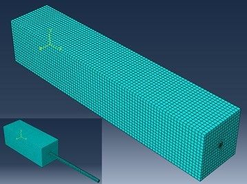
A three-dimensional mesh was modeled in finite elements using the solid element C3D8R, with eight nodes, with three degrees of freedom per node (displacements in the X, Y and Z directions) and reduced integration. The C3D8R element has 6 faces and four integration points per face, as shown in Figure 4. In the tension stiffening element mesh, 44400 thousand elements were used, with 47315 nodes, as shown in Figure 5.


The computer simulation was performed by applying axial displacements, according to the experimental test performed, shown in Figure 6a. Despite the finite element mesh having 80 cm in length, it were monitored the difference between the axial displacements, referring to the direction, of points A and B spaced 70 cm apart and located 5 cm from the upper and lower faces, respectively, as shows Figure 6b. These points correspond to the places where the LVDTs were fixed for measuring the axial displacement during the experimental test.

Representation of the reinforced concrete tension stiffening test: a) experimental configuration; b) numerical representation.
The numerical analysis was implemented by gradually applying a displacement at point A of 0.0096 m in the U1 direction, with . In point B, displacement restrictions were applied in the three directions, . Thus, the values referring to axial deformations were obtained through the application of Equation 10:
where is the displacement in the U1 direction of point A and is the initial distance of 0.70 m, between point A and point B.
The modeling was performed considering a static problem. Thus, it was decided to use the Static General tool, available at ABAQUS, which uses the direct method for solving systems of equations using the Full Newton solution technique or pure Newton. The automatic increment was chosen, in which the user determines the initial, maximum and minimum increment size. An initial increment of 1E-007 m was used. Concrete and steel were modeled separately and, for concrete-steel interaction, perfect bond was considered, so that the tension stiffening effect on the response was isolated.
5.2 Plasticity Model
To model the tension of the elements, the Concrete Damaged Plasticity (CDP) model was used, in which the nonlinear behavior of the concrete is based on the concept of isotropic elastic damage, which aims to represent the stiffness degradation associated with the irreversible damage that it occurs during the fracture process, in combination with isotropic plasticity, to describe the damage mechanisms, called “softening” in tensile and “crushing” in compression. In this context, local damage models assume that nonlinear behavior is different in relation to tensile and compression [2828 D. S. Simulia, Abaqus 6.11 Theory Manual. Providence, RI, USA: DS Simulia Corp., 2011.], [2929 L. M. D. S. Soares, “Análise numérica não linear de ligações pilares laje fungiforme,” M.S. thesis, Univ. Nova, Lisboa, 2016.].
On the contrary of the concrete models based on smeared crack, the CDP does not present a tool that can capture the development of the crack at the point of integration of the material. However, it is possible to introduce the concept of an effective crack direction in order to obtain a graphic visualization of crack patterns in the concrete structure. It is assumed that the cracking starts at points where the plastic strain, , equivalent to tensile is greater than zero and the maximum main plastic strain is positive. The direction of the vector normal to the crack plane is assumed to be parallel to the direction of the maximum main plastic stress [3030 D. S. Simulia, Abaqus 6.12 Analysis User’s Manual. Providence, RI, USA: DS Simulia Corp., 2012.].
To use the CDP model, it is necessary to define some parameters of plasticity, described in Table 2, which, in this study, were chosen based on the values used by several researchers, such as Jankowiak and Lodygowski [3333 T. Jankowiak and T. Lodygowski, "Identification of parameters of concrete damage plasticity constitutive model," Found. Civ. Environ. Eng., vol. 6, no. 1, pp. 53–69, 2005.], Birtel and Mark [3434 V. Birtel and P. Mark, “Parameterised finite element modelling of RC beam shear failure,” in ABAQUS Users’conf., May 2006, pp. 95–108.] and Ors et al. [3535 D. M. F. Ors, H. O. Okail, and A. H. Zaher, "Modeling of shear deficient beams by the mixed smeared/discrete cracking approach," HBRC J., vol. 12, no. 2, pp. 123–136, Aug 2016, http://dx.doi.org/10.1016/j.hbrcj.2014.11.002.
http://dx.doi.org/10.1016/j.hbrcj.2014.1...
]. Regarding the dilatation angle, , it is usually used between 30° and 40° to describe the behavior of the concrete [3636 W. S. A. Nana, T. T. Bui, A. Limam, and S. Abouri, "Experimental and numerical modelling of shear behaviour of full-scale RC slabs under concentrated loads," Structures, vol. 10, pp. 96–116, May 2017, http://dx.doi.org/10.1016/j.istruc.2017.02.004.
http://dx.doi.org/10.1016/j.istruc.2017....
], [3737 R. Malm, Shear Cracks in Concrete Structures Subjected to In-Plane Stresses. Stockholn: Department of Civil and Architectural Engineering, KTH, 2006.].
5.2.1 Constitutive laws
As the CDP model allows to insert a table with the behavior of the concrete related to the tensile, the analytical models of tension stiffening were introduced after being calibrated with the experimental results.
For the behavior under compression, the model proposed by Hognestad [3838 E. Hognestad, Study of Combined Bending and Axial Load in Reinforced Concrete Members (Bulletin Series 399). Champaign: University of Illinois Urbana-Champaign, 1951.] and Kent and Park [3939 D. C. Kent and R. Park, "Flexural members with confined concrete," J. Struct. Div., vol. 97, no. 7, pp. 2703–2722, Aug 1971.], represented by Equation 11, was used, applying the peak stress and the peak strain values obtained from experimental tests.
where is peak stress in compression, adopted as the compressive strength value experimentally obtained, and of the strain related to peak stress.
For the steel of the reinforcement bar, a perfect elastoplastic model was adopted, considering the experimental results.
6 RESULTS AND DISCUSSION
6.1 Experimental results
The experimental load-strain curves of the tests of reinforced concrete elements for mixtures R0, R25 and R50 are shown in Figure 7. The experimental curve of the direct tensile test of the isolated steel bar is also presented.

Experimental results for tension stiffening elements without recycled aggregate (R0) and with substitution of 25% (R25) and 50% (R50) of natural aggregate for recycled aggregate.
It appears that all tension stiffening elements, with conventional concrete or recycled concrete, exhibit a behavior similar to that predicted in Figure 1, with a linear phase followed by a baseline of constant force in which multiple cracking occurs. After this phase, the elements showed an increase in loading, with a stiffness lower than that initially verified, and close to the stiffness presented by the isolated steel bar. It appears that after cracking, the force in the element is greater than the force in the isolated bar, demonstrating the contribution of concrete between cracks to the mechanical behavior of the reinforced concrete element.
The average results of the properties of the concrete elements under tensile test, before and after the cracking phase, are presented in Table 3. It is verified that the presence of the recycled aggregate affected the behavior of the tension stiffening element, with an increase of up to 15% in the cracking stress (F1) and 19.4% increase in deformations (Δε) during the multiple cracking process (phase 2, Figure 1). The stiffness of the element, before and after cracking, was less influenced by the recycled aggregate since the steel stiffness affects these properties more strongly.
From the difference between the load value on the element and the load value on the steel bar, the contribution of the concrete matrix to the behavior of the element (tension stiffening effect) was obtained, as shown in Figure 8 to Figure 10. Assessing the stress-strain behavior of concrete elements, it appears that, after the appearance of the first crack, when the stress reaches the tensile strength shown in Table 4, there is a sudden reduction in the resistant strength of the material (softening), followed by the maintenance of this strength until deformations of the order of 3.5/1000. The substitution of the natural aggregate for recycled aggregate contributed to an increase in the peak stress in tensile, in the strain corresponding to the peak stress and in the elastic modulus of about 15%, 33% and 10%, respectively.


6.2 Parametric study of analytical models to determine the tension stiffening effect
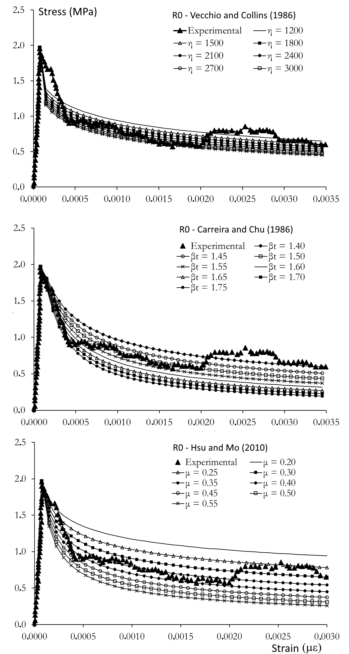
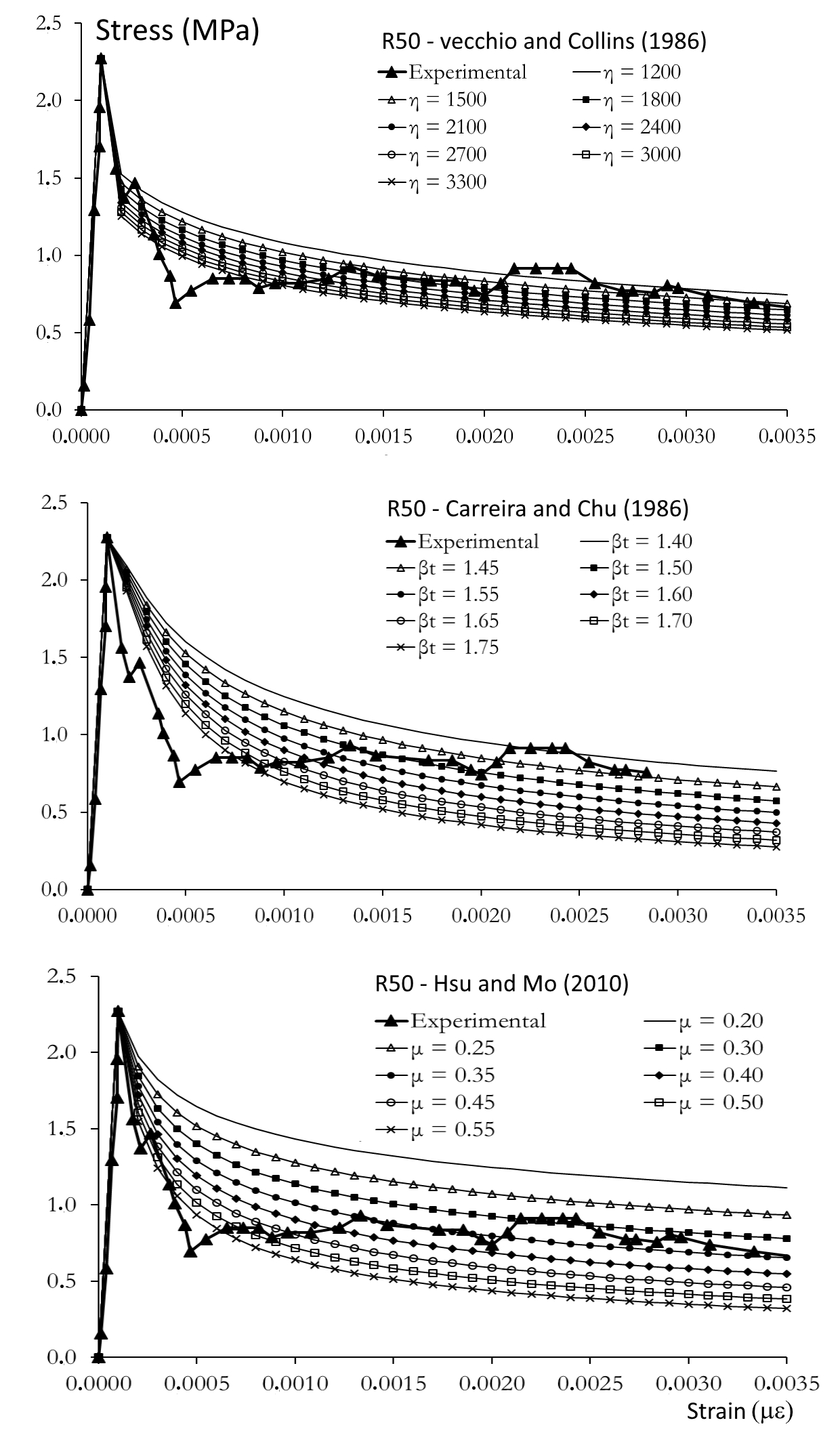
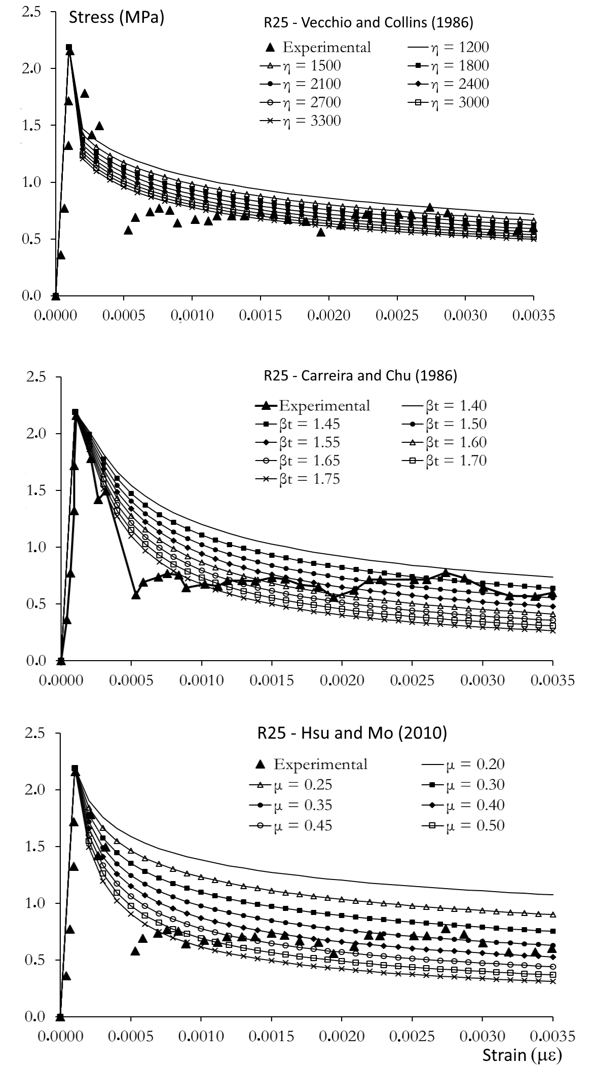
To calibrate the analytical models, a parametric study was carried out in which several values of the parameters , and were tested in the models proposed by Carreira and Chu [2222 D. J. Carreira and K. H. Chu, "Stress-strain relationship for reinforced concrete in tension," ACI J., vol. 83, no. 1, pp. 21–28, Jan 1986.], Hsu and Mo [2323 T. T. C. Hsu and Y. L. Mo, Unified Theory of Concrete Structures. Chichester, UK: Wiley, 2010.] and Vecchio and Collins [22 F. J. Vecchio and M. P. Collins, "The modified compression-field theory for reinforced concrete elements subjected to shear," ACI J. Proc., vol. 83, no. 2, pp. 219–231, Oct 1986.], respectively, and compared with the experimental results. The results are shown in Figure 8 to Figure 10 for conventional concrete, concrete with 25% recycled aggregate and concrete with 50% recycled aggregate, respectively. The values obtained for the parameters and the prediction errors of each model, when compared with the experimental results, are shown in Table 5.
The model by Vecchio and Collins [22 F. J. Vecchio and M. P. Collins, "The modified compression-field theory for reinforced concrete elements subjected to shear," ACI J. Proc., vol. 83, no. 2, pp. 219–231, Oct 1986.] was initially tested with a value of η equal to 200, as proposed by the authors, however the theoretical values of stresses, after the peak, were much higher than the values obtained in the experimental result. Values varying between 1500 and 3000 were then tested. For conventional concrete, investigated in this study, a value of η equal to 1500 was the one that best adjusted the theoretical curve to the experimental result, with an error of less than 1%. For concrete with recycled aggregate, values of η equal to 1800 and 2700 were obtained, with errors of about 1%.
Although the model by Vecchio and Collins [22 F. J. Vecchio and M. P. Collins, "The modified compression-field theory for reinforced concrete elements subjected to shear," ACI J. Proc., vol. 83, no. 2, pp. 219–231, Oct 1986.] does not fit well with the modeling of the tension stiffening behavior, especially in the second phase of the curve, immediately after the peak, it appears that the parameter used for conventional concrete does not fit in the modeling of the concrete with recycled aggregate. This fact was also identified in the other models used.
Compared with the model used previously, it appears that the Carreira and Chu model [2222 D. J. Carreira and K. H. Chu, "Stress-strain relationship for reinforced concrete in tension," ACI J., vol. 83, no. 1, pp. 21–28, Jan 1986.] has greater versatility with respect to the ability to model the stress-strain curves, as well as the model presented by Hsu and Mo [2323 T. T. C. Hsu and Y. L. Mo, Unified Theory of Concrete Structures. Chichester, UK: Wiley, 2010.], as can be seen in Figures 8, Figure 9 and Figure 10. For small variations in the experimental adjustment parameters βt and μ, presented in Equation 7 and Equation 8, respectively, a significant variation in the tension stiffening behavior was verified. The parameter βt ranged from 1.45 to 1.70, while the parameter μ ranged from 0.25 to 0.50.

Table 5 indicates the values of adjustment parameters that best suit the experimental results, considering each model and each type of concrete. The comparison between these parameters indicates that the analytical models obtained to predict the behavior of conventional concrete do not apply to recycled concrete, even when using the 25% substitution content, whose effect on mechanical strength is not so relevant. This proves the initial hypothesis established in this study that, the mathematical relations already established in the design standards for conventional concrete structures can be used to predict the structural behavior of recycled reinforced concrete, there must be an adjustment in the parameters used or a modification of the models.
6.3 Modeling of the reinforced concrete elements
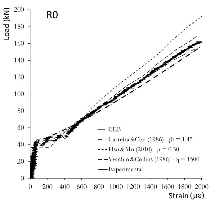
Figure 8, Figure 9 and Figure 10 show the experimental results of the tension stiffening test compared to the numerical models. In the numerical models, the stress-strain diagrams used for concrete under tensile were obtained from appropriate tension stiffening models, using the parameters presented in Table 5. For the purpose of comparison with design standards, the analytical model presented by CEB [11 Comité Euro-International du Béton, Design Manual on Cracking and Deformation (Bulletin d’Information 158). 1985.] is also shown in Figure 11, Figure 12 and Figure 13. It appears that the numerical model was able to predict the overall behavior of the tension stiffening element with an acceptable approximation. To prediction the load and the strain of the first crack of the element, shown in Table 6, the greatest differences between the numerical value and the experimental value, of the order of 19% for the force and 39% for the strain , were verified when the Vecchio and Collins [22 F. J. Vecchio and M. P. Collins, "The modified compression-field theory for reinforced concrete elements subjected to shear," ACI J. Proc., vol. 83, no. 2, pp. 219–231, Oct 1986.] model was used to determine the tension stiffening effect. The Hsu and Mo [2323 T. T. C. Hsu and Y. L. Mo, Unified Theory of Concrete Structures. Chichester, UK: Wiley, 2010.] model was the one that best fitted to conventional concrete, with an error of 3.1% in the predicted , and the Carreira and Chu model [2222 D. J. Carreira and K. H. Chu, "Stress-strain relationship for reinforced concrete in tension," ACI J., vol. 83, no. 1, pp. 21–28, Jan 1986.] resulted in a maximum error of 6.85% in predicted for recycled concrete.

Comparison between numerical models, analytical model and experimental result for the tension stiffening element with conventional concrete R0.

Comparison between numerical models, analytical model and experimental result for the tension stiffening element with recycled concrete R25.

Comparison between numerical models, analytical model and experimental result for the tension stiffening element with recycled concrete R50.
To evaluate the numerical modeling in the prediction of the post-cracking behavior of the tension stiffening element, the areas under the load-strain curves (numerical, analytical and experimental), up to the 2000 µε deformation, were calculated and the error was calculated by the relation between these areas. The results are shown in Table 7.
Comparison between numerical, analytical and experimental results of reinforced concrete tension stiffening elements.
The maximum error obtained by the numerical models was about 14% when the Hsu and Mo model [2323 T. T. C. Hsu and Y. L. Mo, Unified Theory of Concrete Structures. Chichester, UK: Wiley, 2010.] was used in the analytical modeling of the tension stiffening of conventional concrete. In fact, evaluating Figure 9, it is observed that, after the multiple cracking phase, the ascending phase of this numerical curve is more rigid than the other models and then the experimental result. For this phase, the numerical model with the Vecchio and Collins [22 F. J. Vecchio and M. P. Collins, "The modified compression-field theory for reinforced concrete elements subjected to shear," ACI J. Proc., vol. 83, no. 2, pp. 219–231, Oct 1986.] curve presents the best approximation for conventional concrete, with an error of 0.77%, while the model with the Carreira and Chu [2222 D. J. Carreira and K. H. Chu, "Stress-strain relationship for reinforced concrete in tension," ACI J., vol. 83, no. 1, pp. 21–28, Jan 1986.] curves more adequately model the element with recycled concrete, with a maximum error of 0.82%.
Regarding the analytical model proposed by CEB [11 Comité Euro-International du Béton, Design Manual on Cracking and Deformation (Bulletin d’Information 158). 1985.], it appears that the main difference concerns the load-strain behavior in Phase 2 (see Figure 1). While the numerical models and the experimental result indicate a baseline on the curve, with constant load during the multiple cracking process, the CEB model shows an increase in load during this phase. However, the maximum prediction error using the normative prescription was 5.24%, which shows a potential for predicting the behavior of tension stiffening elements with conventional or recycled concrete.
6.3.1 Monitoring the distribution of stresses and strains in the tension stiffening element
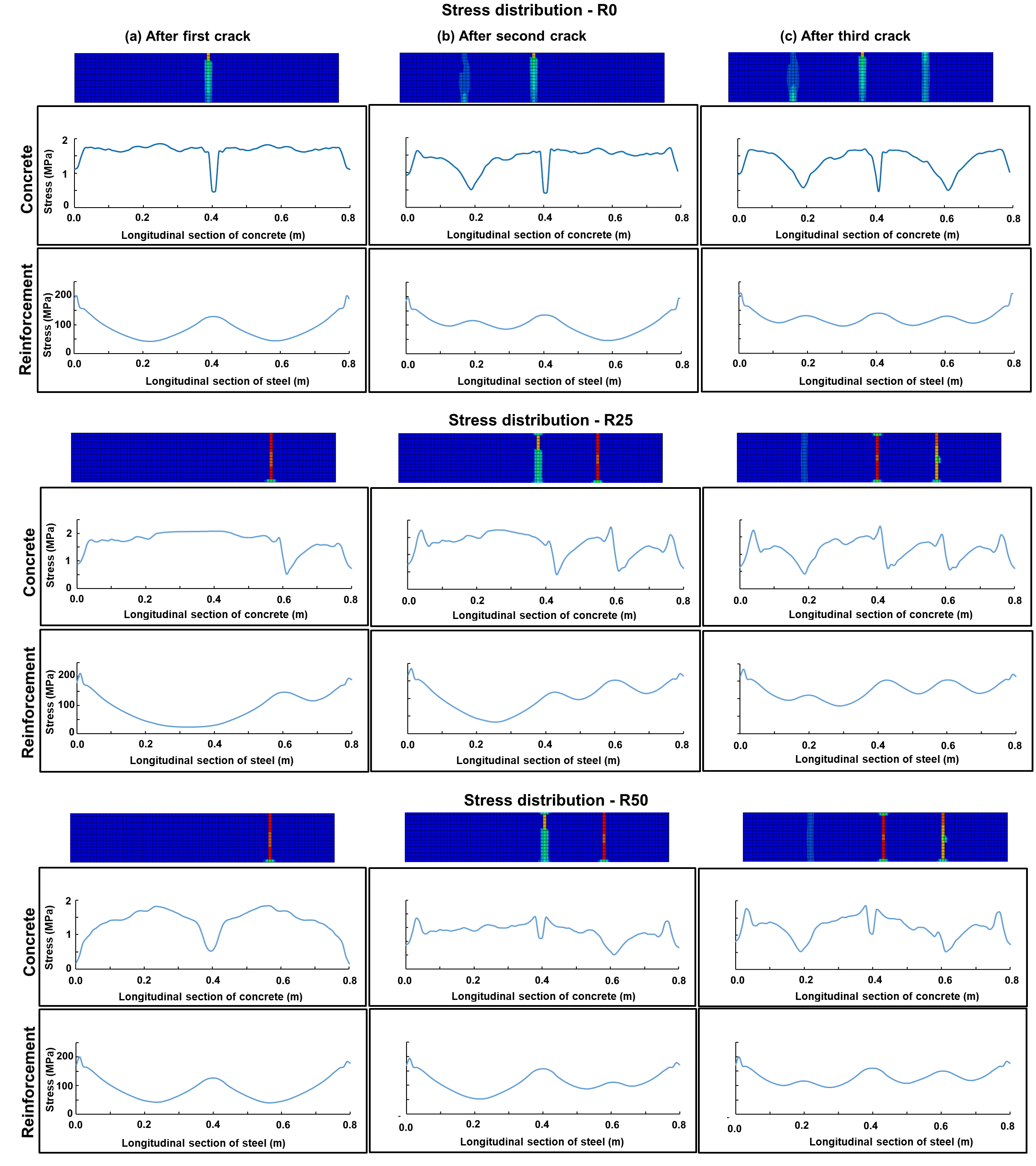
According to the theory of tension stiffening element cracking [11 Comité Euro-International du Béton, Design Manual on Cracking and Deformation (Bulletin d’Information 158). 1985.], after the appearance of the first crack, there is a variation on the distribution of stresses inside the element and, at the crack region, there is a reduction in the concrete stress (which can go to zero) and an increase in tension in the reinforcement. Using the numerical model, it was possible to monitor the development of element cracking and map the level of stresses and strains in concrete and steel.
The experimental results of the tension stiffening test indicate the appearance of three or four main cracks spaced along its length, as shown in Figure 14. The numerical models managed to capture this behavior indicating the appearance of three cracks in all analyzed elements, as shows Figure 15. Despite the appearance of the first crack being in a random region, changing according to the type of concrete, it appears that the final spacing between cracks remained equal to 20 cm. The experimental results indicate an average spacing of 11.3 cm, since in some specimens a greater number of cracks appeared.


Stress distribution in concrete and in reinforcement along the elements after: a) first crack; b) second crack and c) third crack.
The variation of stresses in the steel bar and in the concrete were monitored along the length of the element during the multiple cracking phase and it is shown in Figure 15. The tension was obtained in a node located inside the concrete, halfway between the face of the element and the reinforcement bar, that is, at a distance of 37.5 mm from the external face.
With the appearance of the first crack (Figure 15a), at the crack region, there is a reduction in the stress in the concrete and an increase in the steel stress, since there is a transfer of stresses between the two components. A similar fact is observed when there is the appearance of the second (Figure 15b) and third (Figure 15c) cracks. It is possible to observe, however, that the stresses in the concrete between cracks remain high, indicating the occurrence of the tension stiffening effect, with the contribution of the concrete between cracks to the total strength.
Throughout the cracking process, it appears that, with the appearance of a new crack, there is a redistribution of stresses, and at the point where the crack appears, the steel bar becomes more tensioned and the concrete has a reduction in the capacity to transmit efforts. However, different from what is proposed in the classic tension stiffening cracking model [11 Comité Euro-International du Béton, Design Manual on Cracking and Deformation (Bulletin d’Information 158). 1985.], which proposes that in the crack region the stresses in the concrete go to zero, it is realized in the computational model that the concrete, even in the cracked region, can transmit a small portion of efforts. This phenomenon, called interlocking, is predicted by Prado and Van Mier [4040 E. P. Prado and J. G. M. Van Mier, "Effect of particle structure on mode I fracture process in concrete," Eng. Fract. Mech., vol. 70, no. 14, pp. 1793–1807, Sep 2003., http://dx.doi.org/10.1016/S0013-7944(03)00125-5.
http://dx.doi.org/10.1016/S0013-7944(03)...
] for conventional concrete, and corresponds to the friction that the crack faces impose on the relative displacement and which is influenced by the type of aggregate.
In addition to the variation in stresses along the length of the element, it is expected that the stresses in the concrete will vary along the cross section, since the transfer of stresses, after cracking, is made from the steel bar to the concrete. Using numerical simulation, it was possible to monitor the development of stresses at two points in the concrete cross section, as shown in Figure 16: close to the surface and inside the concrete. Evaluating the non-cracked concrete, it appears that the stresses measured inside the concrete (Point P2) are practically constant while the stresses measured on the surface (Point P1) have a parabolic shape along the length of the element.

Assessing the distribution of plastic deformations inside the concrete (Figure 16), it appears that there is a variation along the cross section. In the cracked section (S1), it can be seen that the deformation of the concrete is greater on the external surface and it decreases as it approaches the steel bar, indicating the maintenance of a certain level of bond that allows the development of stresses in the concrete. In the section S2, formed of intact concrete, a difference is also verified between the deformation in the surface and the deformation inside the concrete, but with less intensity, which is compatible with the level of stresses observed in this section.
7 CONCLUSIONS
Reinforced concrete elements produced with normal concrete and recycled concrete, containing 25% and 50% of recycled aggregate in substitution to the conventional aggregate, were experimentally evaluated under direct tensile and analyzed through numerical and analytical models.
All tension stiffening elements showed multiple cracking under uniaxial tensile. After the cracking process, the observed load values remained higher than the values observed in the steel bar tested separately, confirming the contribution of concrete between cracks (tension stiffening effect) for the strength of the reinforced concrete element. The recycled concrete element presented higher cracking stress and greater deformations in the multiple cracking phase than the conventional concrete element, confirming the influence of the addition of recycled aggregate on the mechanical behavior.
Three analytical models of tension stiffening, with different mathematical equations, were compared with the experimental stress-strain diagrams obtained for the isolated matrix. It is verified that the values obtained for modeling of conventional concrete cannot adequately predict the tension stiffening behavior of concrete with recycled aggregate. For that, new parameters had to be obtained. The mathematical model proposed by Carreira and Chu (1986)22 D. J. Carreira and K. H. Chu, "Stress-strain relationship for reinforced concrete in tension," ACI J., vol. 83, no. 1, pp. 21–28, Jan 1986. obtained better approximations with the experimental results for the behavior of conventional concrete and for concrete with 50% recycled aggregate, but with different adjustment parameters equal to 1.45 and 1.55, respectively.
The numerical evaluation of reinforced concrete elements indicates that the type of analytical model adopted for tension stiffening affects the prediction of structural behavior, both in the approximation of curves and in the determination of crack loads. Comparing the models used, it can be seen that, for conventional concrete elements, the tension stiffening model proposed by Vecchio and Collins managed to approximate the areas under the curve (0.77% of error), but does not present as good approximation in the post-cracking behavior regarding the model proposed by Carreira and Chu, who managed to predict the behavior of the elements with conventional and recycled concrete with reasonable precision, provided that the appropriate parameters for each type of concrete were used. Despite presenting an error of 5.24% in the prediction of the element behavior, the analytical model proposed by CEB showed a good approximation, especially when it is considered that it did not change the original parameters proposed by the standard.
The monitoring of the stress distribution along the element, during the loading and cracking processes, demonstrated that there is a stress redistribution as new cracks appear in the concrete, making it possible to identify the tension stiffening effect, that is, the contribution of the concrete between cracks. At the crack region, it is possible to identify that the concrete stresses reduce, but do not reach zero, also contributing to the strength of the tension stiffening element.
The numerical results indicate that, in the same section of the element, there is a variation of plastic deformations and stresses along the cross section. This variation affects the form of stress distribution in the concrete along the length of the element, which is no longer uniform when measured inside the section, and becomes parabolic when measured on the concrete surface.
ACKNOWLEDGMENTS
The authors acknowledge the support from CAPES and CNPq for this study.
-
Financial support: CNPq (303931/2016-7)
-
How to cite: M. P. Martins, C. S. Rangel, M. Amario, J. M. F. Lima, P. R. L. Lima, and R. D. Toledo Filho, “Modelling of tension stiffening effect in reinforced recycled concrete,” Rev. IBRACON Estrut. Mater., vol. 13, no. 6, e13605, 2020, https://doi.org/10.1590/S1983-41952020000600005
REFERENCES
-
1Comité Euro-International du Béton, Design Manual on Cracking and Deformation (Bulletin d’Information 158). 1985.
-
2F. J. Vecchio and M. P. Collins, "The modified compression-field theory for reinforced concrete elements subjected to shear," ACI J. Proc., vol. 83, no. 2, pp. 219–231, Oct 1986.
-
3R. Ian Gilbert, "Tension stiffening in lightly reinforced concrete slabs," J. Struct. Eng., vol. 133, no. 6, pp. 899–903, Jun 2007, http://dx.doi.org/10.1061/(ASCE)0733-9445(2007)133:6(899)
» http://dx.doi.org/10.1061/(ASCE)0733-9445(2007)133:6(899) -
4S. Khalfallah and D. Guerdouh, "Tension stiffening approach in concrete of tensioned members," Int. J. Adv. Struct. Eng., vol. 6, no. 1, pp. 1–6, Jan 2014, http://dx.doi.org/10.1007/s40091-014-0051-8
» http://dx.doi.org/10.1007/s40091-014-0051-8 -
5R. Ian Gilbert and R. F. Warner, "Tension stiffening in reinforced concrete slabs," J. Struct. Div., vol. 104, no. 2, pp. 1885–1900, 1978.
-
6C. K. Choi and S. H. Cheung, "Tension stiffening model for planar reinforced concrete members," Comput. Struc., vol. 59, no. 1, pp. 179–190, Apr 1996, http://dx.doi.org/10.1016/0045-7949(95)00146-8
» http://dx.doi.org/10.1016/0045-7949(95)00146-8 -
7A. Scanlon and D. Murray, "Time-dependent reinforced concrete slab deflections," J. Struct. Div., vol. 100, no. 8, pp. 1911–1924, Sep 1974.
-
8A. K. Gupta and S. R. Maestrini, "Tension-stiffness model for reinforced concrete bars," J. Struct. Eng., vol. 116, no. 3, pp. 769–790, Mar 1990, http://dx.doi.org/10.1061/(ASCE)0733-9445(1990)116:3(769)
» http://dx.doi.org/10.1061/(ASCE)0733-9445(1990)116:3(769) -
9P. C. M. Gonçalves, “Betão com agregados reciclados – análise comentada da legislação existente,” M.S. thesis, Inst. Sup. Téc., UTL, Lisboa, 2007.
-
10J. Xiao, Y. Sun, and H. Falkner, "Seismic performance of frame structures with recycled aggregate concrete," Eng. Struct., vol. 28, no. 1, pp. 1–8, Jan 2006, http://dx.doi.org/10.1016/j.engstruct.2005.06.019
» http://dx.doi.org/10.1016/j.engstruct.2005.06.019 -
11V. Corinaldesi, V. Letelier, and G. Moriconi, "Behaviour of beam-column joints made of recycled-aggregate concrete under cyclic loading," Constr. Build. Mater., vol. 25, no. 4, pp. 1877–1882, Apr 2011, http://dx.doi.org/10.1016/j.conbuildmat.2010.11.072
» http://dx.doi.org/10.1016/j.conbuildmat.2010.11.072 -
12J. Xiao, W. Li, Y. Fan, and X. Huang, "An overview of study on recycled aggregate concrete in China (1996–2011)," Constr. Build. Mater., vol. 31, pp. 364–383, Jun 2012, http://dx.doi.org/10.1016/j.conbuildmat.2011.12.074
» http://dx.doi.org/10.1016/j.conbuildmat.2011.12.074 -
13C. S. Rangel, M. Amario, M. Pepe, Y. Yao, B. Mobasher, and R. D. Toledo Fo., "Tension stiffening approach for interface characterization in recycled aggregate concrete," Cement Concr. Compos., vol. 82, pp. 176–189, Sep 2017., http://dx.doi.org/10.1016/j.cemconcomp.2017.06.009
» http://dx.doi.org/10.1016/j.cemconcomp.2017.06.009 -
14J. A. Carneiro, P. R. L. Lima, M. B. Leite, and R. D. Toledo Filho, "Compressive stress–strain behavior of steel fiber reinforced-recycled aggregate concrete," Cement Concr. Compos., vol. 46, pp. 65–72, Feb 2014, http://dx.doi.org/10.1016/j.cemconcomp.2013.11.006
» http://dx.doi.org/10.1016/j.cemconcomp.2013.11.006 -
15M. Etxeberria, A. R. Marí, and E. Vázquez, "Recycled aggregate concrete as structural material," Mater. Struct., vol. 40, no. 5, pp. 529–541, Jun 2007, http://dx.doi.org/10.1617/s11527-006-9161-5
» http://dx.doi.org/10.1617/s11527-006-9161-5 -
16I. S. Ignjatović, S. B. Marinković, Z. M. Mišković, and A. R. Savić, "Flexural behavior of reinforced recycled aggregate concrete beams under short-term loading," Mater. Struct., vol. 46, no. 6, pp. 1045–1059, Jun 2013, http://dx.doi.org/10.1617/s11527-012-9952-9
» http://dx.doi.org/10.1617/s11527-012-9952-9 -
17R. V. Silva, J. Brito, and R. K. Dhir, "Prediction of the shrinkage behavior of recycled aggregate concrete: a review," Constr. Build. Mater., vol. 77, pp. 327–339, Feb 2015, http://dx.doi.org/10.1016/j.conbuildmat.2014.12.102
» http://dx.doi.org/10.1016/j.conbuildmat.2014.12.102 -
18P. H. Bischoff, "Effects of shrinkage on tension stiffening and cracking in reinforced concrete," Can. J. Civ. Eng., vol. 28, no. 3, pp. 363–374, 2001., http://dx.doi.org/10.1139/l00-117
» http://dx.doi.org/10.1139/l00-117 -
19G. Kaklauskas, V. Gribniak, D. Bacinskas, and P. Vainiunas, "Shrinkage influence on tension stiffening in concrete members," Eng. Struct., vol. 31, no. 6, pp. 1305–1312, Jun 2009, http://dx.doi.org/10.1016/j.engstruct.2008.10.007
» http://dx.doi.org/10.1016/j.engstruct.2008.10.007 -
20S. M. Allam, M. S. Shoukry, G. E. Rashad, and A. S. Hassan, "Evaluation of tension stiffening effect on the crack width calculation of flexural RC members," Alex. Eng. J., vol. 52, no. 2, pp. 163–173, Jun 2013, http://dx.doi.org/10.1016/j.aej.2012.12.005
» http://dx.doi.org/10.1016/j.aej.2012.12.005 -
21M. Kosior-Kazberuk and M. Grzywa, "Recycled aggregate concrete as material for reinforced concrete structures," J. Sustain. Archit. Civ. Eng., vol. 7, no. 2, pp. 60–66, Jun 2014, http://dx.doi.org/10.5755/j01.sace.7.2.7135
» http://dx.doi.org/10.5755/j01.sace.7.2.7135 -
22D. J. Carreira and K. H. Chu, "Stress-strain relationship for reinforced concrete in tension," ACI J., vol. 83, no. 1, pp. 21–28, Jan 1986.
-
23T. T. C. Hsu and Y. L. Mo, Unified Theory of Concrete Structures. Chichester, UK: Wiley, 2010.
-
24Comité Euro-International du Béton. Fédération Internationale de la Précontrainte, CEB-FIP Model Code 1990: Design Code, 1993.
-
25T. Wang and T. T. C. Hsu, "Nonlinear finite element analysis of concrete structures using new constitutive models," Comput. Struc., vol. 79, no. 32, pp. 2781–2791, Dec 2001, http://dx.doi.org/10.1016/S0045-7949(01)00157-2
» http://dx.doi.org/10.1016/S0045-7949(01)00157-2 -
26T. Dede and Y. Ayvaz, "Nonlinear analysis of reinforced concrete beam with/without tension stiffening effect," Mater. Des., vol. 30, no. 9, pp. 3846–3851, Oct 2009, http://dx.doi.org/10.1016/j.matdes.2009.02.003
» http://dx.doi.org/10.1016/j.matdes.2009.02.003 -
27C. S. Rangel, “Influência de agregados graúdos reciclados nas propriedades estruturais de concretos de resistência normal e de alto desempenho,” M.S. thesis, Univ. Fed. Rio de Janeiro, Rio de Janeiro, 2015.
-
28D. S. Simulia, Abaqus 6.11 Theory Manual. Providence, RI, USA: DS Simulia Corp., 2011.
-
29L. M. D. S. Soares, “Análise numérica não linear de ligações pilares laje fungiforme,” M.S. thesis, Univ. Nova, Lisboa, 2016.
-
30D. S. Simulia, Abaqus 6.12 Analysis User’s Manual Providence, RI, USA: DS Simulia Corp., 2012.
-
31J. Lee and G. L. Fenves, "Plastic-damage model for cyclic loading of concrete structures," J. Eng. Mech., vol. 124, no. 8, pp. 892–900, Aug 1998., http://dx.doi.org/10.1061/(ASCE)0733-9399(1998)124:8(892)
» http://dx.doi.org/10.1061/(ASCE)0733-9399(1998)124:8(892) -
32H. Kupfer, H. K. Hilsdorf, and H. Rusch, "Behavior of concrete under biaxial stresses," ACI J. Proc., vol. 66, no. 8, pp. 656–666, Jan 1969.
-
33T. Jankowiak and T. Lodygowski, "Identification of parameters of concrete damage plasticity constitutive model," Found. Civ. Environ. Eng., vol. 6, no. 1, pp. 53–69, 2005.
-
34V. Birtel and P. Mark, “Parameterised finite element modelling of RC beam shear failure,” in ABAQUS Users’conf., May 2006, pp. 95–108.
-
35D. M. F. Ors, H. O. Okail, and A. H. Zaher, "Modeling of shear deficient beams by the mixed smeared/discrete cracking approach," HBRC J., vol. 12, no. 2, pp. 123–136, Aug 2016, http://dx.doi.org/10.1016/j.hbrcj.2014.11.002
» http://dx.doi.org/10.1016/j.hbrcj.2014.11.002 -
36W. S. A. Nana, T. T. Bui, A. Limam, and S. Abouri, "Experimental and numerical modelling of shear behaviour of full-scale RC slabs under concentrated loads," Structures, vol. 10, pp. 96–116, May 2017, http://dx.doi.org/10.1016/j.istruc.2017.02.004
» http://dx.doi.org/10.1016/j.istruc.2017.02.004 -
37R. Malm, Shear Cracks in Concrete Structures Subjected to In-Plane Stresses Stockholn: Department of Civil and Architectural Engineering, KTH, 2006.
-
38E. Hognestad, Study of Combined Bending and Axial Load in Reinforced Concrete Members (Bulletin Series 399). Champaign: University of Illinois Urbana-Champaign, 1951.
-
39D. C. Kent and R. Park, "Flexural members with confined concrete," J. Struct. Div., vol. 97, no. 7, pp. 2703–2722, Aug 1971.
-
40E. P. Prado and J. G. M. Van Mier, "Effect of particle structure on mode I fracture process in concrete," Eng. Fract. Mech., vol. 70, no. 14, pp. 1793–1807, Sep 2003., http://dx.doi.org/10.1016/S0013-7944(03)00125-5
» http://dx.doi.org/10.1016/S0013-7944(03)00125-5 -
41C. S. Lin and A. C. Scordelis, "Nonlinear analysis of RC shells of general form," J. Struct. Div., vol. 101, no. 3, pp. 523–538, 1975.
Edited by
Publication Dates
-
Publication in this collection
30 Oct 2020 -
Date of issue
2020
History
-
Received
24 July 2019 -
Accepted
30 Mar 2020