
Abstract
The present work simulates and analyzes numerically two one-way walls (OW) with a central unforeseen cut-out-opening, which were previously tested experimentally. The models are based in the Finite Element Method and consider nonlinear behavior of the concrete material, such as hardening/softening and fracture. The first wall model was analyzed without any type of strengthening whereas the second one was strengthened using externally bonded CFRP along the opening edges. The strengthening modeling process was discussed through three different approaches suitable for unidirectional CFRP wrap. Load results were presented with load-displacement and load-strain curves that evidenced the flexural behavior of these structures. The crack pattern and failure mode observed showed good agreement with reported literature. The CFRP strengthening presented a small influence in the load capacity for big opening size.
Keywords:
strengthening; CFRP; concrete; opening; wall
Resumo
O presente trabalho simula e analisa numericamente duas paredes de uma direção (UD) com abertura não prevista, as quais foram testadas previamente de forma experimental. Os modelos se baseiam no Método de Elementos Finitos e consideram o comportamento não linear do concreto, como o endurecimento/amolecimento e fratura. O primeiro modelo de parede foi analisado sem reforço estrutural, enquanto o segundo foi reforçado com PRFC colado externamente envolvendo a abertura. O processo de modelagem do reforço é discutido através de três diferentes abordagens que são adequadas a tecidos unidirecionais de PRFC. Os resultados de carga são apresentados em gráficos carga-deslocamento e carga-deformação que evidenciam o comportamento a flexão desses elementos. O padrão de fissuração e modo de ruptura observado mostra boa concordância com o reportado na literatura. O reforço com PRFC apresentou uma pequena influência na capacidade de carga para a maior abertura.
Palavras-chave:
reforço; PRFC; concreto; abertura; parede
1 INTRODUCTION
Reinforced concrete structures are subjected to the creation of openings for different purposes. When this change in the element's continuity is foreseen on the original project, it is usually employed additional steel bars near the openings, intended to strengthen the structure. However, there are cases in which the openings are not anticipated. The cut-out openings are referred to the removal of both concrete and reinforcement after the wall was casted, thus limiting its strengthening possibility.
In general, cut-out openings are a result of incompatibilities between projects (mechanical, electrical, and plumbing), construction faults and architectural modifications to adapt existing structures to the users' needs and current standards. According to Popescu et al. [11 C. Popescu, G. Sas, C. Sabău, and T. Blanksvärd, "Effect of cut-out openings on the axial strength of concrete walls," J. Struct. Eng., vol. 142, pp. 2–6, 2016, http://dx.doi.org/10.1061/(ASCE)ST.1943-541X.0001558.
http://dx.doi.org/10.1061/(ASCE)ST.1943-...
], in recent years, there has been increasing interest in enlarging spaces by connecting adjacent rooms through creating openings in existing solid walls.
Walls can be constructed with various support conditions that influence its deflected shape, crack pattern and strength when an axial load is applied. There are two wall types related to the support condition (see Figure 1). The panel can be restrained at the top and bottom only, behaving in one way (OW), or it can also have lateral side restrains, behaving in two-way (TW). Ho et al. [22 N. M. Ho, J. H. Doh, and S. Fragomeni, "Instability analysis of reinforced concrete walls with various support conditions," Struct. Des. Tall Spec. Build., vol. 26, no. 7, pp. e1353, 2017., http://dx.doi.org/10.1002/tal.1353.
http://dx.doi.org/10.1002/tal.1353...
] described OW walls as elements that deform along the loading direction showing a single curvature. In contrast, TW walls deform along with both the horizontal and vertical directions with double curvature, commonly encountered in core walls of high-rise buildings.
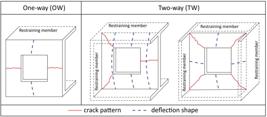
One-way and two-way behavior of axially loaded RC walls. Adapted from Popescu et al. [1111 C. Popescu, G. Sas, T. Blanksvard, and B. Taljsten, "Concrete walls weakened by openings as compression members: A review," Eng. Struct., vol. 89, pp. 172–190, 2015, http://dx.doi.org/10.1016/j.engstruct.2015.02.006.
http://dx.doi.org/10.1016/j.engstruct.20... ].
The structural behavior of wall panels has been subject of numerous experimental and numerical studies. Saheb and Desayi [33 S. M. Saheb and P. Desayi, "Ultimate Strength of RC wall panels in one way in plane action," J. Struct. Eng., vol. 115, no. 10, pp. 2617–2630, 1989, http://dx.doi.org/10.1061/(ASCE)0733-9445(1989)115:10(2617).
http://dx.doi.org/10.1061/(ASCE)0733-944...
] and Doh and Fragomeni [44 J. H. Doh and S. Fragomeni, "Evaluation of experimental work on concrete walls in one and two-way action," Aust. J. Struct. Eng., vol. 6, no. 1, pp. 37–52, 2005, http://dx.doi.org/10.1080/13287982.2005.11464943.
http://dx.doi.org/10.1080/13287982.2005....
] focused in provide more reliable and accurate wall design equations based in experimental tests. Robinson et al. [55 G. P. Robinson, A. Palmeri, and S. A. Austin, "Design methodologies for one way spanning eccentrically loaded minimally or centrally reinforced pre-cast RC panels," Eng. Struct., vol. 56, pp. 1945–1956, 2013, http://dx.doi.org/10.1016/j.engstruct.2013.07.041.
http://dx.doi.org/10.1016/j.engstruct.20...
] evaluated design methodologies applicable to pre-cast RC panels and concluded that current design equations underestimated the load capacity of slender RC walls. Fragomeni et al. [66 S. Fragomeni, P. Mendis, and W. Grayson, "Review of reinforced-concrete wall design formulas," ACI Struct. J., vol. 91, pp. 521–529, 1994.] showed that the RC wall design equation given in the ACI 318 [77 American Concrete Institute, Building Code Requirements for Structural Concrete, ACI 318, 2019.] code fails to recognize any contribution to load capacity from the side restrains in TW walls.
There are two main methods of designing reinforced concrete walls (RC walls) found in standards codes: (1) a simplified design method and (2) column-theory based method. The simplified methods are based on empirical formulations obtained through experimental tests and are found in CSA A23.3 [88 Canadian Standards Association, Design of Concrete Structures, CSA A23.3, 2004.]; AS 3600 [99 Australian Standard, Concrete Structures, AS 3600, 2001.]; ACI 318 [1010 American Concrete Institute, Building Code Requirements For Structural Concrete, ACI 318, 2019.]. Although the easy and direct application, this method lacks a more generalized scope once it results from experimental adjustments. The methods based in the column theory comprises a more refined calculation considering stress-strain compatibilities and the equilibrium of the element cross-section. The column-theory based method represents a viable alternative that provides more accurate results according to Popescu et al. [1111 C. Popescu, G. Sas, T. Blanksvard, and B. Taljsten, "Concrete walls weakened by openings as compression members: A review," Eng. Struct., vol. 89, pp. 172–190, 2015, http://dx.doi.org/10.1016/j.engstruct.2015.02.006.
http://dx.doi.org/10.1016/j.engstruct.20...
] and can be found in ABNT NBR 16055 [1212 Associação Brasileira de Normas Técnicas, Parede de Concreto Moldada no Local para a Construção de Edificações – Requisitos e Procedimentos, NBR 16055, 2012.] and EN 1992 [1313 European Standard, Eurocode 2 – Design of Concrete Structures – Part 1-1: General Rules and Rules for Buildings, EN 1992, 2004]. In the case of RC walls with cut-out opening, no straightforward methods to evaluate the ultimate capacity was found in standards codes.
Saheb and Desayi [1414 S. M. Saheb and P. Desayi, "Ultimate strength of RC wall panels with openings," J. Struct. Eng., vol. 116, no. 6, pp. 1565–1577, 1990.] reported the first systematic study of concrete walls with openings, tested in OW and TW action that investigated the influence of various parameters on the ultimate load. In their study, the authors introduced Equation 1 to calculate the new load capacity Pcuoc after the creation of an opening. This equation considers the position and size of an opening in the wall by means of the coefficient α, which is obtained according Figure 2. The constants k1 and k2 advent from the linear adjustment of experimental results, whereas Pcuc is the ultimate load of an identical panel without opening computed following the ACI318 [1010 American Concrete Institute, Building Code Requirements For Structural Concrete, ACI 318, 2019.].

Opening parameter α for the method proposed by Saheb and Desayi [1414 S. M. Saheb and P. Desayi, "Ultimate strength of RC wall panels with openings," J. Struct. Eng., vol. 116, no. 6, pp. 1565–1577, 1990.].
Recent research has shown that the strength of these panels can decrease dramatically as a function of the size of the opening (Guan et al. [1515 H. Guan, C. Cooper, and D. J. Lee, "Ultimate strength analysis of normal and high strength concrete wall panels with varying opening configurations," Eng. Struct., vol. 32, no. 5, pp. 1341–1355, 2010.]; Doh et al. [1616 J. Doh, Y. Loo, and S. Fragomeni, “Concrete walls with and without openings supported on three sides,” in Incorporating Sustainable Practice in Mechanics and Structures of Materials, S. Fragomeni, Ed., CRC Press, 2010, pp. 209–214.], Popescu et al. [11 C. Popescu, G. Sas, C. Sabău, and T. Blanksvärd, "Effect of cut-out openings on the axial strength of concrete walls," J. Struct. Eng., vol. 142, pp. 2–6, 2016, http://dx.doi.org/10.1061/(ASCE)ST.1943-541X.0001558.
http://dx.doi.org/10.1061/(ASCE)ST.1943-...
]). Consequently, modifications have been made in empirical formulas to consider the presence of the opening that assumes a linear relationship between the reduction in the wall strength and the opening size.
Strengthening methods have been employed to recover load capacity in cut-out opening walls. There are traditional methods to strengthen wall panels, such as increase element thickness and to create a frame around the opening using reinforced concrete [55 G. P. Robinson, A. Palmeri, and S. A. Austin, "Design methodologies for one way spanning eccentrically loaded minimally or centrally reinforced pre-cast RC panels," Eng. Struct., vol. 56, pp. 1945–1956, 2013, http://dx.doi.org/10.1016/j.engstruct.2013.07.041.
http://dx.doi.org/10.1016/j.engstruct.20...
]. The difficulty of execution associated with the materials weight and time consuming are the main disadvantages of these two methods. Carbon fiber reinforced polymers (CFRP) have presented as alternative strengthening material and become common in civil engineering as available rehabilitation method on several types of structures. Hansen et al. [1717 C. S. Hansen, G. Sas, and B. Taljsten, “FRP strengthening of RC walls with openings,” in IV Int. Conf. Adv. Compos. Constr., 2009, pp. 202–213.] highlight that CFRP advantages lie on the low weight to high strength ratio, good mechanical properties, and the easy application techniques.
Nowadays, we evidence a lack of procedures about how calculating the amount of CFRP needed to strengthen cut-out opening walls and predict its update load capacity. Enochsson et al. [1818 O. Enochsson, J. Lundqvist, B. Taljsten, P. Rusinowski, and T. Olofsson, "CFRP strengthened openings in two-way concrete slabs - an experimental and numerical study," Constr. Build. Mater., vol. 21, no. 4, pp. 810–826, 2007.] introduced a rational method to obtain the CFRP cross-section area to strengthening RC walls with cut-out opening. The method was originally proposed to strengthen RC slab and is based on BBK04 [1919 Svensk Byggtjanst, Boverkets Handbok om Betongkonstruktioner – BBK04 [The Swedish Building Administrations Handbook of Concrete Structures]. Swedish, 2004] recommendations. However, it has been used in experimental studies of RC walls (Lima et al. [2020 M. M. Lima, J. H. Doh, and M. N. Hadi, "Experimental study on RC walls with opening strengthened by externally bonded CFRP," J. Compos. Constr., vol. 23, no. 2, 2019.], Mohammed et al. [2121 B. Mohammed, L. Ean, and M. Malek, "One way RC wall panels with openings strengthened with cfrp," Constr. Build. Mater., vol. 40, pp. 575–587, 2013.]).
Mohammed et al. [2121 B. Mohammed, L. Ean, and M. Malek, "One way RC wall panels with openings strengthened with cfrp," Constr. Build. Mater., vol. 40, pp. 575–587, 2013.] performed a series of experimental tests in OW wall panels to predict the ultimate load of strengthened walls. As the outcome of their research, the authors presented a formulation to predict the ultimate load adjusted to CFRP strengthened walls with opening. Additionally, they noted that when CFRP was placed on 45o at the opening corners, load capacity was higher than when it was placed along the opening corners. Also, the strengthening efficiency was reduced when the opening size increase.
Numerical studies have assisted in understanding the behavior of strengthened wall panels better. However, they considered a perfect rigid connection between concrete and CFRP. This paper presents different aspects of numerical modeling strengthening, considering the interface between materials. In addition, it contributes to showing the structural behavior of strengthened OW wall through load-displacement and load-strain curves. The developed models used as reference the experiments reported by Mohammed et al. [2121 B. Mohammed, L. Ean, and M. Malek, "One way RC wall panels with openings strengthened with cfrp," Constr. Build. Mater., vol. 40, pp. 575–587, 2013.].
2 EXPERIMENTAL
The studied RC walls were tested by Mohammed et al. [2121 B. Mohammed, L. Ean, and M. Malek, "One way RC wall panels with openings strengthened with cfrp," Constr. Build. Mater., vol. 40, pp. 575–587, 2013.] and their dimension was 800x400x40 mm (heigh:length:thickness), supported by two hinged steel plates with 20x400x40 mm located at its top and bottom edges. In the walls center was created an unforeseen cut-out-opening without additional reinforcement bars. Two tested specimens were identified by WO4a and WO4b (strengthened) in which the nomenclature refers to the opening size and the belonging wall series. One layer of reinforcement was placed centrally within the wall cross-section mainly to avoid offset creep and shrinkage effects in the concrete. It was composed of 5 mm diameter steel bars in each direction with a spacing of 60 mm. The average yield strength was 478 MPa and elastic modulus of 205 GPa.
In the wall WO4b, strengthening was provided by externally bonded (EB) CFRP unidirectional wrap bonded along the opening in both faces. The average value of concrete strength was measured at the age of testing the wall panels using cube specimens. For these walls, the concrete compressive strength was 19.73 MPa on WO4a and 18.83 MPa on WO4b. The cylinder compressive strength was assumed 80% of cube compressive strength. Tensile strength (ft) was estimated by the mean value of the three cylinder splitting tests and adopted equal 1.46 MPa. Modulus of elasticity (E) and Poisson (ν) ratio of the concrete cylinder were 21 GPa and 0.21, respectively. The wall panels were tested using one 30-ton hydraulic jack that transmitted a uniformly distributed load across the top support plate through a 20 mm diameter steel bar at an eccentricity of t/6.
Figure 3 illustrates the RC walls studied in this paper. The experimental tests provided the load capacity, crack pattern and failure mode of the wall panels. Full details of the reference models can be found in Mohammed et al. [2121 B. Mohammed, L. Ean, and M. Malek, "One way RC wall panels with openings strengthened with cfrp," Constr. Build. Mater., vol. 40, pp. 575–587, 2013.].

3 NUMERICAL MODEL
The nonlinear finite element software ATENA Studio (version 5) and GiD (version 10) were used in the present study to investigate the behavior and ultimate strength of two RC wall structures. In these finite element programs, the constitutive relationships implemented can simulate the behavior of reinforced concrete structures, including cracking, crushing and reinforcement yielding. GiD was used as a pre-processor of the numerical simulation where the models were built and input files for ATENA were created. Afterward, post-processing analysis was carried out in ATENA, which provided deformed shape, stress and strain diagrams.
The present study is based on the two experimental wall panels: WO4a and WO4b (strengthened). Nomenclature adopted in the developed models was kept equal experimental, but information about the employed mesh type was added as suffix part.
Loading and support plates of 20 mm thickness and 400 mm width were modeled at the load application and reaction lines. Elements CCIsoTetra simulated the steel profiles employed to prevent premature failure due to high stress concentration in the concrete. Maximum element dimension was set 40 mm. Contact connection between plates and the concrete was considered perfect bond without the possibility of slip.
The wall geometry was equal to experimental and the model was divided into CCIsoBrick elements. This element combined with constitutive material allows for plastic deformation, cracking in three orthogonal directions, and crushing. The most important aspect of this element is the treatment of nonlinear material properties Pizzocchero [2222 A. Pizzocchero, “Calibration and validation of ATENA concrete material model with respect to experimental data,” Ph.D. dissertation, Univ. Studi Padova, Padova, 2015.].
Reinforcement was modeled as discrete elements (CCIsoTruss) positioned in the wall middle plane. The bars presented uniaxial behavior in their own direction governed by a bi-linear stress-strain curve with mechanical properties set equal to the experimental test. The bars diameter was 5 mm with average proof yield strength of 478 MPa and modulus of elasticity of 205 GPa. A perfect bond condition was considered between the concrete and the reinforcement, so dowel effect was neglected.
For the solution of the nonlinear iteration problem, an iterative Newton-Raphson method was chosen, where the load was applied incrementally. Convergence parameters used to obtain the solution for each load increment was set 1%, 1% and 0.01% corresponding to the displacement, residual force, and energy errors, respectively. A controlled vertical displacement (0.8 mm) was divided into load steps (100), which acted on an eccentric line in the top plate. Monitoring points measured displacements and strains at points of interest that are presented in the results.
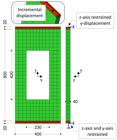
Figure 4 illustrates a typical wall model and its boundaries conditions. These conditions and the loading scheme were imposed in accordance with the experimental test. The bottom plate had a support line that prevented z and y displacements and kept free rotation around the x-axis, whereas the top plate had a loading line that prevented z displacement. The positions of the loading line and bottom support line were set to match the eccentricity associated with the experimental tests.
The constitutive model that simulated the concrete was CC3DNonLinCementitious2, which is fully incremental and capable of reproducing material and geometrical nonlinearities, both considered. It combines constitutive models for tensile (fracturing) and compressive (plastic) behavior illustrated in Figure 5. The fracture model is based on the classical orthotropic smeared crack formulation and crack band model. It employs the Rankine failure criterion, exponential softening, and it can be used as rotated or fixed crack model. The hardening/softening plasticity model is based on Mentrey-Willam failure surface Cervenka et al. [2323 V. Cervenka, L. Jendele, and J. Cervenka, ATENA Program Documentation, Part 1: Theory. Prague: Cervenka Consulting, 2016.].

Fracture-plastic constitutive model of the concrete. Adapted from Cervenka et al. [2323 V. Cervenka, L. Jendele, and J. Cervenka, ATENA Program Documentation, Part 1: Theory. Prague: Cervenka Consulting, 2016.].
Some parameters that were not determined experimentally were calculated using the fib Model Code 2010 (2013) equations and GiD recommendations (see Table 1.) Basic parameters were maintained equal to experimental values.
3.1 Mesh models
Initially, the concrete mesh was investigated on the non-strengthened wall (WO4a) using 12 different meshes that were divided into linear and quadratic groups, each one with six models with particular solid elements in the analysis. Linear group was discretized by CCIsoBrick elements of eight nodes, while quadratic group used the same elements but with 20 nodes. Six mesh configurations were tested in each group, which were named A (fine mesh) to F (coarse mesh). As an example, the model WO4a-F corresponds to the non-strengthened wall where mesh type F is adopted in the concrete.
Taking the WO4a-C model as reference, a second analysis was performed for the strengthened model (WO4b) using three different mesh types of mesh for the CFRP discretization, varying between meshes 1 (fine), 2 (medium) and 3 (coarse). As an example, the model WO4b-C2 indicates the strengthened wall where mesh type C is adopted in the concrete and mesh type 2 in the CFRP. Table 2 presents the geometric properties of the meshes analyzed.
The use of solid elements with linear approximations is susceptible to the so-called locking effect that arises mainly in bending-dominated situations and in the limit of incompressibility Reese et al. [2424 S. Reese, P. Wriggers, and B. Reddy, "A new locking-free brick element technique for large deformation problems in elasticity," Comput. Struc., vol. 75, no. 3, pp. 291–304, 2000.]. Thus, the developed models used four elements along the wall thickness to reproduce properly the bending/buckling through vertical load and to reduce the locking effect.
3.2 Strengthening modeling
3.2.1 CFRP
Three strengthening approaches were studied in this paper, all of them can represent the orthotropic nature of CFRP wrap with unidirectional fibers correctly. Experimental results were used to validate numerical models in terms of ultimate strength, crack pattern and failure mode. The ultimate strength represented the maximum load that the model was able to resist.
The first approach modeled CFRP as 2D membrane elements with composite material properties. This type of element works in-plane stress state and can reproduce compression and tension effects. However, it did not consider strengthening flexural stiffness. The material CCCombinedMaterial allows combining a brittle material with internal reinforcement. This is exactly the situation in the CFRP wrap, which consists of a brittle epoxy resin and a carbon fiber reinforcing net. The carbon fibers are considered as smeared, thus only its average effect is treated.
The second approach used 2D shell elements that accounts for the bending stiffness of CFRP wrap. Nevertheless, a major contribution of this effect was not expected due to the small thickness of the wrap (1mm). Epoxy resin can use the fracture-plastic material CC3DNonLinCementitious2 as the basic shell material and the carbon fibers are included as special reinforcement layers. This approach requires the carbon fibers position, which in this case, was in the middle of the element thickness.
Finally, 3D shell elements were used to model CFRP. These elements are particularly useful for structures that combine solid 3D elements and shell elements because they do not imply any additional shell kinematic constraint that would harm an adjacent 3D solid element. They are designed for bent shells and to analyze these structures. They require far fewer finite elements compared to a similar analysis using standard hexahedral elements.
All the above cases need mechanical properties of epoxy resin and carbon fibers that may be difficult to find. Tables3 and 4 contain the wrap parameters used in this paper. Some of them were found in manufacturer catalog Mapei [2525 Mapei. “Design guide.” https://cdnmedia.mapei.com/docs/global-technical-specification/application-of-composite-materials.pdf (accessed Jan. 5, 2019).
https://cdnmedia.mapei.com/docs/global-t...
] while others estimated according to Sajdlov [2626 T. Sajdlov, ATENA Program Documentation, Part 4-9. Prague: Cervenka Consulting, 2006.].
3.2.2 Interface
A possible failure mode of a reinforced concrete element strengthened in flexure with externally CFRP occurs in the boundary area between fiber and matrix, a so-called peeling failure, which causes the fiber to slip from the surrounding matrix Taljsten [2727 B. Taljsten, FRP Strengthening of Existing Concrete Structures. Lulea: Lulea University of Technology, 2006.]. In this case, it is necessary to include interface connection on strengthened models considered as contact volume with zero thickness.
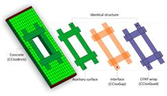
The present work used CCIsoGap elements to simulate the interface between the concrete and the CFRP. The discretization of these elements required compatible finite element meshes, therefore the boundary surfaces (concrete/CFRP) need to have coincident nodes to make interface use possible. The strengthened models had elements with different mesh sizes at the interface edges. Thus, it was necessary to create an auxiliary surface with identical structure as the CFRP to match the nodes. A perfectly rigid connection was admitted between the concrete and this auxiliary surface while interface connected the auxiliary surface and the CFRP wrap. This procedure is illustrated in Figure 6.
The constitutive material for interface element (CC3DInterface) is illustrated in Figure 7, which is based on Mohr-Coulomb criterion with tension cut-off. The relation for a general two-dimensional case is given in terms of tractions on the interface planes, relative sliding and the opening displacements. Parameters as tensile strength (ft), shear cohesion (c) and friction (mu) describe real physical properties and can be obtained by pull-off tests, single and double direct shear tests, among others. Otherwise, they may be estimated according to Sajdlov [2626 T. Sajdlov, ATENA Program Documentation, Part 4-9. Prague: Cervenka Consulting, 2006.].

Constitutive model of interface element. Adapted from Gholamhoseini [2828 A. Gholamhoseini, "Experimental and finite element study of ultimate strength of continuous composite concrete slabs with steel decking," Int. J. Adv. Struct. Eng., vol. 10, no. 1, pp. 85–97, 2018.]
The coefficients Knn and Ktt denote the initial elastic normal and shear stiffness, respectively. Normal and tangential stiffness can be estimated based on the stiffness of the adjacent finite elements. There are two additional stiffness values that need to be specified in the ATENA input denoted as Kn,min and Kt,min that are required for numerical purpose. These values are used only after the failure of the element to preserve the positive definiteness of the global system of equations. Theoretically, after the interface failure, the interface stiffness should be zero, which would mean that the global stiffness would become undefined. This minimal stiffness is recommended to be about 0.01-0.001 times the initial stiffness according to Gholamhoseini (2018). The values of interface parameters adopted in developed models are presented in Table 5.
4 RESULTS
4.1 Mesh sensitivity
Non-strengthened wall (WO4a): Table 6 presents a summary of the ultimate load obtained from the finite element mesh analysis (Punum) and the comparison with ultimate experimental load (Puexp) and theoretical prediction (Puocc) using Equation 1. The structural behavior was investigated through load-displacement and load-strain curves obtained from monitor points. Figure 8 shows the displacements and strain measured in linear (8-nodes) and quadratic (20-nodes) models before the ultimate load is reached.
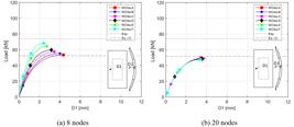
It is noted in Table 6 linear elements had load capacity ranged between 73% and 93% of experimental results. However, when the numerical result was compared with theoretical, computed with Equation 1, the ratio of the ultimate loads was non-conservative and varied between 1% and 28%. In general, linear models also obtained higher loads when compared with quadratic elements models. Model type WO4a-F (coarse mesh) was the one which most fitted experimental result and achieved 68.25 kN. Besides that, ultimate load increased proportionally to element dimension in linear models. Figure 8a shown finer meshes had the out-of-plane displacement (D1) increased which resulted in less stiffness models. On the other hand, coarser meshes presented a brittle behavior caused by the crack opening inside the element. Due to high mesh dependence obtained, linear models (8-nodes elements) were dismissed for the other analyses.
Quadratic models (20-nodes) presented low dependence of the element discretization on the structural behavior. The ultimate loads of the numerical models were practically constant and ranged 65-68% of experimental. Furthermore, the numerical models' results showed reasonable agreement with theoretical load (Equation 1), in which the ratios varied between 90-94%. The behavior was different of linear group because the fine mesh (WO4a-A) obtained higher capacity.
Despite of the lack of experimental data regarding the stiffness of the wall in Mohammed et al. [2121 B. Mohammed, L. Ean, and M. Malek, "One way RC wall panels with openings strengthened with cfrp," Constr. Build. Mater., vol. 40, pp. 575–587, 2013.] and Mohammed et al. [3131 B. S. Mohammed, L. W. Ean, and K. Hossain, "M. CFRP Composites for strengthening of reinforced concrete walls with openings," Int. J. Eng. Res. Appl., vol. 1, pp. 1841–1852, 2011.], the out-of-plane displacement (D1) of the numerical models was approximately 4 mm and all models showed similar stiffness (Figure 8b). The mesh type of WO4a-C with quadratic elements was chosen for the strengthened models analysis, when considering the reasonable agreement between the ultimate load of numerical models and theoretical prediction, and also the crack pattern by the time ultimate load was reached in the numerical models.
The Table 7 presents the load results of strengthened models (WO4b). CFRP mesh discretization did not cause a significant influence on model strength. It was possible to have a better understanding of stress and strain distribution on CFRP when fine mesh type WO4b-C1 was used, provided by the elevated number of elements. Besides that, the computational cost, in this case, was significantly increased and took approximately four hours to complete analysis, whereas coarse mesh consumed a few minutes. The coarse mesh WO4b-C3, however, violated conditional break criteria of force equilibrium when modeled with membrane and 3D shell elements. The ultimate load remained among 61-63% of experimental. Lima et al. [2929 M. Lima, J. Doh, M. Hadi, and D. Miller, "The effects of cfrp orientation on the strengthening of reinforced concrete structures," Struct. Des. Tall Spec. Build., vol. 25, no. 15, pp. 759–784, 2016.] obtained similar results (64%) using software ABAQUS, however, the authors used a perfectly rigid connection instead of interface elements in contact with concrete/CFRP.
Figure 9 shows the load-strain curve of different approaches used to simulate strengthening. Monitoring points G1, G2 and G3 used to record strain were placed 5 mm inside the wall to avoid interference with external CFRP. In general, all strengthened models presented similar behavior and load capacity. Monitor G1 recorded the horizontal strain in the opening middle span. Figure 9a shows the load interval (30-35 kN) where two vertical cracks appeared near the opening edges and caused a reduction of the horizontal tension strain. Monitors G2 and G3 were fixed at the same localization but on opposite faces of the wall, in a way that one should be in tension and the other in compression, respectively. The vertical strain recorded by these two monitors are presented in Figure 99c. It is possible to note that, by the time the ultimate load was reached, the horizontal cross-section of 3D shell model was predominantly compressed. The G2 monitor of 3D shell model showed 0.07 tension strain which is small when compared with the membrane and 2D shell models, 0.20 and 0.30, of tension strain, respectively. Hence, the compression in the 3D shell model was higher than in the other two models and the neutral axis was near the tension face, which could be explained by the admission of the flexural stiffness of these elements. The G3 monitor showed that when the ultimate load was reached, the maximum compression strain was 0.15%;thus, the concrete did not crushed at this point.

4.2 Assessment of eccentricity in the ultimate load
The load eccentricity has a significant influence on the strength capacity of RC walls affecting the ultimate load and failure mode (ElMetwally et al. [3030 S. E. ElMetwally, F. Ashour, and W. F. Chen, "Instability analysis of eccentrically loaded concrete walls," J. Struct. Eng., vol. 116, no. 10, pp. 2862–2880, 1990.], Doh and Fragomeni [44 J. H. Doh and S. Fragomeni, "Evaluation of experimental work on concrete walls in one and two-way action," Aust. J. Struct. Eng., vol. 6, no. 1, pp. 37–52, 2005, http://dx.doi.org/10.1080/13287982.2005.11464943.
http://dx.doi.org/10.1080/13287982.2005....
]). Experimental tests reproduced in this paper handled eccentricity in the order of millimeters, which may be difficult to control. Using its experimental value (6.66 mm), the developed models obtained the ultimate loads presented in Tables 6 and 7. These results were lower than ones in experimental tests, therefore a parametric study was made with varying load eccentricity to investigate its influence on load capacity.
New numerical models were executed, varying the load eccentricity of WO4a-C and WO4b-C1 (CFRP strengthened, membrane elements). The eccentricity was varied from 2.6 mm to 6.6 mm (experimental), with increments of one millimeter. The load-strain behavior of these models is presented in Figure 10.
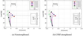
As the loading line approximates the wall middle-plane, compression overcomes flexural behavior in models with and without CFRP strengthening. In the present work, the eccentricity e2 (4,6mm) was the limit in which, below it, the cross-section was entirely compressed at ultimate load.
The best fit of ultimate load (99% of experimental) occurred when eccentricity was equal to 2.6 mm (e4), which means 4 millimeters change of experimental report. Thus, the horizontal cross-section in the wall center was entirely compressed for small eccentricity (e4=2.6 and e3=3.6 mm) and showed also tensile strain for larger eccentricity (e1=5.6 and e0=6.6 mm) (see Figure 10).
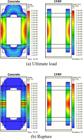
To investigate the divergence in the final load, an analytical approach based on ultimate limit state was applied. The two column strips were joined, and the resulting cross-section used to evaluate the resistance of the wall WO4a. It was assumed that the resulting cross-section is mostly subjected to the normal force and uniaxial bending. Thus, a moment-force interaction diagram (see Figure 11) was constructed with the resistances of the materials obtained in the tests and a parabolic-rectangular for stress concrete distribution in compression. In addition, Figure 11 shows the bending moment due to the numerical ultimate load (Punum) considering the initial eccentricity 6.6mm (1st order effect) and the deflection D1 (2nd order effect); and also the rupture point that occurred in the post-peak. Despite the ultimate load and the bending moment due to the 2nd order effect is near the cross-section's strength limit, the numerical model did not fail at this point. The collapse of the numerical wall model happened due to concrete crushing without yielding of the rebars at the post-peak regime. Therefore, it shows that the numerical model agrees with the analytical results.

4.3 Failure mode
The failure of the models did not occur immediately after reaching the ultimate load. Numerical models showed softening regime where out-of-plane increased as the load decreased. At certain point, it was observed that major horizontal cracks in the tension face cause concrete crushing in the compression face of the wall, therefore causing the failure. The progression until failure is depicted in Figure 12 for the model WO4a-C with original eccentricity (6.6 mm). As it can be seen in Figure 12a by the time ultimate load was reached, typical flexural strains were concentrated in the column strips next to the opening and the vertical steel bars were predominantly compressed.
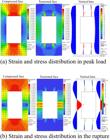
Furthermore, the principal tensile strains were in the span near the opening edges where vertical cracks appeared. Following Figure 12b, the out-of-plane displacement continued to increase and most of the tensile strains moved from the opening span to the column strips center causing major horizontal cracks in this area. Consequently, the rebars experienced tension and the concrete crushing, thus identifying failure in the column strips.
The experimental crack patterns of these walls were described in Mohammed et al. [2121 B. Mohammed, L. Ean, and M. Malek, "One way RC wall panels with openings strengthened with cfrp," Constr. Build. Mater., vol. 40, pp. 575–587, 2013.]. The authors reported that cracks before failure were not evident in wall panels with big openings, which was the case of WO4a and WO4b (strengthened). They reported those two specimens collapsed due to horizontal cracks initiation near the opening edge in column strip. Strengthened wall WO4b also presented CFRP peeled off before the structural collapsed happened.
Figure 13 illustrates a typical crack evolution until the rupture of the numerical models with crack opening filter of 0.01 mm. The crack started vertical near the opening edges and advanced in the direction of the support plates. Afterward, the wall deflection increased, and horizontal cracks appeared in the two-column strips. Although there are horizontal cracks near the opening edges, the critical crack which caused rupture occurred in the center of column strips. The critical crack in the experimental test was also horizontal in the column strip but it appeared close to the opening edge (see Figure 14).


Failure mode in the experimental test. Adapted from Mohammed et al. [2121 B. Mohammed, L. Ean, and M. Malek, "One way RC wall panels with openings strengthened with cfrp," Constr. Build. Mater., vol. 40, pp. 575–587, 2013.].
The strengthened model (WO4b-C1) showed a primary failure caused by CFRP debonding. This phenomenon was indirectly observed comparing the vertical strain in models with membrane and 2D shell elements. Figure 15 illustrates the vertical strain in the concrete and strain in the fiber’s direction of the CFRP wrap. The difference between concrete strain (εc=0.067%) and CFRP strain (εcfrp=0.034%) was small at the peak load (see Figure 15a). However, as the out-of-plane deflection increased, this strain difference was approximately 23 times between the concrete and the CFRP (see Figure 15b). The stiffness of CFRP is higher than the concrete; hence it presents small deformation, which indicates a reduction of adherence forces. After this primary failure, the structural collapse occurred like the non-strengthened model (WO4a-C).
In the strengthened model using 3D shell elements, it was possible to visualize the relative displacement between the materials when primary failure was initiated. Figure 16 shows the debonding process of WO4b-C1 (3D shell). The structural collapse occurred when out-of-plane deflection significantly increased after reaching the ultimate load, similar to the non-strengthened model (WO4a-C).

5 CONCLUSIONS
The present work showed three different approaches of modeling strengthening with externally bonded CFRP in case of OW with openings. Additionally, it provides stiffness curves, obtained numerically, that help to understand better the structural behavior of these elements, which were not provided in recent and limited number of studies (Mohammed et al. [3131 B. S. Mohammed, L. W. Ean, and K. Hossain, "M. CFRP Composites for strengthening of reinforced concrete walls with openings," Int. J. Eng. Res. Appl., vol. 1, pp. 1841–1852, 2011.], Mohammed et al. [2121 B. Mohammed, L. Ean, and M. Malek, "One way RC wall panels with openings strengthened with cfrp," Constr. Build. Mater., vol. 40, pp. 575–587, 2013.]; Lima et al. [2929 M. Lima, J. Doh, M. Hadi, and D. Miller, "The effects of cfrp orientation on the strengthening of reinforced concrete structures," Struct. Des. Tall Spec. Build., vol. 25, no. 15, pp. 759–784, 2016.]) found regarding a strengthened wall with openings.
5.1 Nonstrengthened models (WO4a)
The load capacity of the non-strengthened developed model was not influenced by the mesh discretization when quadratic elements were used. The models presented similar stiffness through all loading stage. Regarding the lack of experimental data published about this test, the model behaved as a typical OW wall showing a single curvature in the panel due to a flexural pattern, with horizontal cracks propagating in the middle of the column strips which lead the structure to failure. The numerical models could reproduce properly the structural behavior of experimental test. Besides that, the ultimate load corresponding to WO4a-C (quadratic) model was 66% of the experimental. The comparison with theoretical prediction presented reasonable results, in which the ultimate load of the developed model achieved 92% of theoretical. As the dimension involved in the tests made by Mohammed et al. [2121 B. Mohammed, L. Ean, and M. Malek, "One way RC wall panels with openings strengthened with cfrp," Constr. Build. Mater., vol. 40, pp. 575–587, 2013.] was small, a parametric study made in this paper shows the relevance of eccentricity in load capacity. The model strength increased by 24% and 50% when load eccentricity was reduced 2 and 4 millimeters, respectively.
5.2 Strengthened models (WO4b)
In general, CFRP discretization had a small influence on the load capacity that remained between 61-63% of experimental. The walls tested in this paper had small ductility due to their reduced dimension; therefore, debonding of CFRP was less relevant to loading capacity. Similar results can be obtained by adopting fixed contact between CFRP and concrete as presented by Lima et al. [2929 M. Lima, J. Doh, M. Hadi, and D. Miller, "The effects of cfrp orientation on the strengthening of reinforced concrete structures," Struct. Des. Tall Spec. Build., vol. 25, no. 15, pp. 759–784, 2016.] using ABAQUS (64% of experimental). The membrane elements provided a higher load capacity to the wall model. However, it is still below experimental and as non-strengthened case a small change on eccentricity could provide better results in terms of load capacity. The collapse of the model occurred after the failure of the bond between CFRP and concrete, which was noted in the post-peak stage. At this stage, the vertical strain in the wall face was about 10 times bigger than in CFRP which may indirectly indicate slipping in membrane and 2D shell elements approaches. Furthermore, the 3D shell elements approach was capable of directly reproducing slipping process between CFRP and concrete. In this case, higher compression of horizontal cross-section in the model center was noted. For future works, experimental measures are required to compare strains in CFRP and the bond-slip relation between materials. In addition, larger scale tests and structures that are more ductile may show the relevance of interface modeling and externally bond strengthening.
ACKNOWLEDGEMENTS
The authors would like to express their gratitude to the Coordenação de Aperfeiçoamento de Pessoal de Nível Superior (CAPES) and the Structural Modeling and Monitoring Laboratory (LABMEM) of the University of Campinas (UNICAMP) for supporting this research. Website: http://www.fec.unicamp.br/~labmem/
-
Financial support: Coordenação de Aperfeiçoamento de Pessoal de Nível Superior (CAPES).
-
How to cite: M. A. Silva, R. A. S. Díaz, L. C. Almeida, and L. M. Trautwein, “Numerical analysis of RC wall with opening and strengthened with CFRP,” Rev. IBRACON Estrut. Mater., vol. 14, no. 1, e14108, 2021, https://doi.org/10.1590/S1983-41952021000100008
REFERENCE
-
1C. Popescu, G. Sas, C. Sabău, and T. Blanksvärd, "Effect of cut-out openings on the axial strength of concrete walls," J. Struct. Eng., vol. 142, pp. 2–6, 2016, http://dx.doi.org/10.1061/(ASCE)ST.1943-541X.0001558
» http://dx.doi.org/10.1061/(ASCE)ST.1943-541X.0001558 -
2N. M. Ho, J. H. Doh, and S. Fragomeni, "Instability analysis of reinforced concrete walls with various support conditions," Struct. Des. Tall Spec. Build., vol. 26, no. 7, pp. e1353, 2017., http://dx.doi.org/10.1002/tal.1353
» http://dx.doi.org/10.1002/tal.1353 -
3S. M. Saheb and P. Desayi, "Ultimate Strength of RC wall panels in one way in plane action," J. Struct. Eng., vol. 115, no. 10, pp. 2617–2630, 1989, http://dx.doi.org/10.1061/(ASCE)0733-9445(1989)115:10(2617)
» http://dx.doi.org/10.1061/(ASCE)0733-9445(1989)115:10(2617) -
4J. H. Doh and S. Fragomeni, "Evaluation of experimental work on concrete walls in one and two-way action," Aust. J. Struct. Eng., vol. 6, no. 1, pp. 37–52, 2005, http://dx.doi.org/10.1080/13287982.2005.11464943
» http://dx.doi.org/10.1080/13287982.2005.11464943 -
5G. P. Robinson, A. Palmeri, and S. A. Austin, "Design methodologies for one way spanning eccentrically loaded minimally or centrally reinforced pre-cast RC panels," Eng. Struct., vol. 56, pp. 1945–1956, 2013, http://dx.doi.org/10.1016/j.engstruct.2013.07.041
» http://dx.doi.org/10.1016/j.engstruct.2013.07.041 -
6S. Fragomeni, P. Mendis, and W. Grayson, "Review of reinforced-concrete wall design formulas," ACI Struct. J., vol. 91, pp. 521–529, 1994.
-
7American Concrete Institute, Building Code Requirements for Structural Concrete, ACI 318, 2019.
-
8Canadian Standards Association, Design of Concrete Structures, CSA A23.3, 2004.
-
9Australian Standard, Concrete Structures, AS 3600, 2001.
-
10American Concrete Institute, Building Code Requirements For Structural Concrete, ACI 318, 2019.
-
11C. Popescu, G. Sas, T. Blanksvard, and B. Taljsten, "Concrete walls weakened by openings as compression members: A review," Eng. Struct., vol. 89, pp. 172–190, 2015, http://dx.doi.org/10.1016/j.engstruct.2015.02.006
» http://dx.doi.org/10.1016/j.engstruct.2015.02.006 -
12Associação Brasileira de Normas Técnicas, Parede de Concreto Moldada no Local para a Construção de Edificações – Requisitos e Procedimentos, NBR 16055, 2012.
-
13European Standard, Eurocode 2 – Design of Concrete Structures – Part 1-1: General Rules and Rules for Buildings, EN 1992, 2004
-
14S. M. Saheb and P. Desayi, "Ultimate strength of RC wall panels with openings," J. Struct. Eng., vol. 116, no. 6, pp. 1565–1577, 1990.
-
15H. Guan, C. Cooper, and D. J. Lee, "Ultimate strength analysis of normal and high strength concrete wall panels with varying opening configurations," Eng. Struct., vol. 32, no. 5, pp. 1341–1355, 2010.
-
16J. Doh, Y. Loo, and S. Fragomeni, “Concrete walls with and without openings supported on three sides,” in Incorporating Sustainable Practice in Mechanics and Structures of Materials, S. Fragomeni, Ed., CRC Press, 2010, pp. 209–214.
-
17C. S. Hansen, G. Sas, and B. Taljsten, “FRP strengthening of RC walls with openings,” in IV Int. Conf. Adv. Compos. Constr., 2009, pp. 202–213.
-
18O. Enochsson, J. Lundqvist, B. Taljsten, P. Rusinowski, and T. Olofsson, "CFRP strengthened openings in two-way concrete slabs - an experimental and numerical study," Constr. Build. Mater., vol. 21, no. 4, pp. 810–826, 2007.
-
19Svensk Byggtjanst, Boverkets Handbok om Betongkonstruktioner – BBK04 [The Swedish Building Administrations Handbook of Concrete Structures]. Swedish, 2004
-
20M. M. Lima, J. H. Doh, and M. N. Hadi, "Experimental study on RC walls with opening strengthened by externally bonded CFRP," J. Compos. Constr., vol. 23, no. 2, 2019.
-
21B. Mohammed, L. Ean, and M. Malek, "One way RC wall panels with openings strengthened with cfrp," Constr. Build. Mater., vol. 40, pp. 575–587, 2013.
-
22A. Pizzocchero, “Calibration and validation of ATENA concrete material model with respect to experimental data,” Ph.D. dissertation, Univ. Studi Padova, Padova, 2015.
-
23V. Cervenka, L. Jendele, and J. Cervenka, ATENA Program Documentation, Part 1: Theory Prague: Cervenka Consulting, 2016.
-
24S. Reese, P. Wriggers, and B. Reddy, "A new locking-free brick element technique for large deformation problems in elasticity," Comput. Struc., vol. 75, no. 3, pp. 291–304, 2000.
-
25Mapei. “Design guide.” https://cdnmedia.mapei.com/docs/global-technical-specification/application-of-composite-materials.pdf (accessed Jan. 5, 2019).
» https://cdnmedia.mapei.com/docs/global-technical-specification/application-of-composite-materials.pdf -
26T. Sajdlov, ATENA Program Documentation, Part 4-9 Prague: Cervenka Consulting, 2006.
-
27B. Taljsten, FRP Strengthening of Existing Concrete Structures Lulea: Lulea University of Technology, 2006.
-
28A. Gholamhoseini, "Experimental and finite element study of ultimate strength of continuous composite concrete slabs with steel decking," Int. J. Adv. Struct. Eng., vol. 10, no. 1, pp. 85–97, 2018.
-
29M. Lima, J. Doh, M. Hadi, and D. Miller, "The effects of cfrp orientation on the strengthening of reinforced concrete structures," Struct. Des. Tall Spec. Build., vol. 25, no. 15, pp. 759–784, 2016.
-
30S. E. ElMetwally, F. Ashour, and W. F. Chen, "Instability analysis of eccentrically loaded concrete walls," J. Struct. Eng., vol. 116, no. 10, pp. 2862–2880, 1990.
-
31B. S. Mohammed, L. W. Ean, and K. Hossain, "M. CFRP Composites for strengthening of reinforced concrete walls with openings," Int. J. Eng. Res. Appl., vol. 1, pp. 1841–1852, 2011.
Edited by
Publication Dates
-
Publication in this collection
18 Dec 2020 -
Date of issue
2021
History
-
Received
12 Feb 2020 -
Accepted
30 May 2020


