Abstracts
OBJECTIVE: To analyze maxillary molar displacement by applying three different angulations to the outer bow of cervical-pull headgear, using the finite element method (FEM). METHODS: Maxilla, teeth set up in Class II malocclusion and equipment were modeled through variational formulation and their values represented in X, Y, Z coordinates. Simulations were performed using a PC computer and ANSYS software version 8.1. Each outer bow model reproduced force lines that ran above (ACR) (1), below (BCR) (2) and through the center of resistance (CR) (3) of the maxillary permanent molars of each Class II model. Evaluation was limited to the initial movement of molars submitted to an extraoral force of 4 Newtons. RESULTS: The initial distal movement of the molars, using as reference the mesial surface of the tube, was higher in the crown of the BCR model (0.47x10⁻⁶) as well as in the root of the ACR (0.32x10⁻⁶) model, causing the crown to tip distally and mesially, respectively. On the CR model, the points on the crown (0.15 x10⁻⁶) and root (0.12 x10⁻⁶) moved distally in a balanced manner, which resulted in bodily movement. In occlusal view, the crowns on all models showed a tendency towards initial distal rotation, but on the CR model this movement was very small. In the vertical direction (Z), all models displayed extrusive movement (BCR 0.18 x10⁻⁶; CR 0.62 x10⁻⁶; ACR 0.72x10⁻⁶). CONCLUSIONS: Computer simulations of cervical-pull headgear use disclosed the presence of extrusive and distal movement, distal crown and root tipping, or bodily movement.
Headgear; Finite Element Method; Tooth movement
OBJETIVO: analisar pelo método dos elementos finitos o deslocamento dos molares superiores frente a três diferentes inclinações do arco externo do aparelho extrabucal na tração do tipo cervical. MÉTODOS: maxila, dentes montados em má oclusão de Classe II e aparelho foram modelados através de formulação variacional e seus valores reproduzidos em coordenadas X, Y e Z. Foram realizadas simulações em microcomputador tipo PC, utilizando o programa ANSYS versão 8.1. Cada modelo de arco externo reproduziu linhas de força que passaram (1) acima (AcCR), (2) abaixo (AbCR) e (3) no centro de resistência (CR) do molar permanente superior de um mesmo modelo portador de má oclusão de Classe II. A avaliação restringiu-se ao movimento inicial dos molares frente à força extrabucal de 4 Newtons. RESULTADOS: o movimento distal inicial dos molares, tendo como ponto de referência a mesial do tubo, foi maior na coroa do modelo AbCR (0,47x10⁻⁶), e maior na raiz do modelo AcCR (0,32x10⁻⁶), provocando inclinações da coroa para distal e mesial, respectivamente. No modelo CR, os pontos na coroa (0,15x10⁻⁶) e raiz (0,12x10⁻⁶) deslocaram-se para distal equilibradamente, resultando em movimento de translação. Em todos os modelos, numa vista oclusal, houve tendência de rotação distal inicial da coroa, porém no modelo CR esse movimento foi muito pequeno. No sentido vertical (Z), todos os modelos revelaram movimento extrusivo (AbCR= 0,18x10⁻⁶; CR= 0,62x10⁻⁶; AcCR= 0,72x10⁻⁶). CONCLUSÃO: a simulação computacional do uso de aparelho extrabucal com tração cervical revelou a ocorrência de movimento extrusivo e distal, podendo ser por inclinação distal de coroa, de raiz ou movimento de translação.
Aparelhos de tração extrabucal; Análise de elemento finito; Movimentação dentária
ONLINE ARTICLE
IMSc in Orthodontics, Federal University of Rio de Janeiro. PhD Student in Orthodontics, Federal University of Rio de Janeiro, (UFRJ)
IIMSc in Orthodontics, UFRJ. Adjunct professor, Vale do Rio Doce University. PhD Student in Orthodontics, UFRJ
IIIMSc in Orthodontics, UFRJ. Professor of Orthodontics, Salgado de Oliveira University, Niterói, RJ. PhD Student in Orthodontics, UFRJ
IVPhD in Metallurgical Engineering/Bioengineering, Fluminense Federal University
VPhD in Materials Science/Implants, Military Institute of Engineering, Adjunct Professor of IME / RJ. Collaborating Professor, Program in Orthodontics, UFRJ. Researcher of the National Council for Scientific and Technological Development
VIPhD in Mechanical Engineering, Rio de Janeiro Pontific Catholic University. Practice in Transformation Metallurgy, major in Mechanical Conformation. Head Professor, Fluminense Federal University
VIIPhD in Orthodontics, Federal University of Rio de Janeiro. Adjunct Professor, Federal University of Rio de Janeiro
Contact address
ABSTRACT
OBJECTIVE: To analyze maxillary molar displacement by applying three different angulations to the outer bow of cervical-pull headgear, using the finite element method (FEM).
METHODS: Maxilla, teeth set up in Class II malocclusion and equipment were modeled through variational formulation and their values represented in X, Y, Z coordinates. Simulations were performed using a PC computer and ANSYS software version 8.1. Each outer bow model reproduced force lines that ran above (ACR) (1), below (BCR) (2) and through the center of resistance (CR) (3) of the maxillary permanent molars of each Class II model. Evaluation was limited to the initial movement of molars submitted to an extraoral force of 4 Newtons.
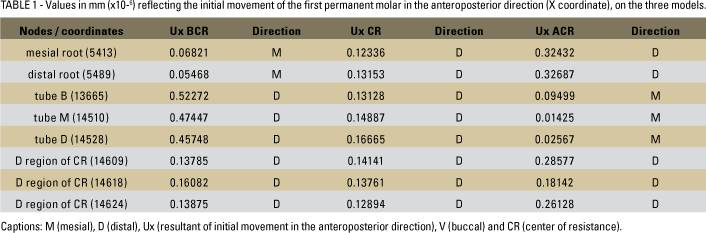
RESULTS: The initial distal movement of the molars, using as reference the mesial surface of the tube, was higher in the crown of the BCR model (0.47x10⁻⁶) as well as in the root of the ACR (0.32x10⁻⁶) model, causing the crown to tip distally and mesially, respectively. On the CR model, the points on the crown (0.15 x10⁻⁶) and root (0.12 x10⁻⁶) moved distally in a balanced manner, which resulted in bodily movement. In occlusal view, the crowns on all models showed a tendency towards initial distal rotation, but on the CR model this movement was very small. In the vertical direction (Z), all models displayed extrusive movement (BCR 0.18 x10⁻⁶; CR 0.62 x10⁻⁶; ACR 0.72x10⁻⁶).
CONCLUSIONS: Computer simulations of cervical-pull headgear use disclosed the presence of extrusive and distal movement, distal crown and root tipping, or bodily movement.
Keywords: Headgear. Finite Element Method. Tooth movement.
Editor's summary
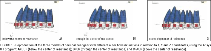
This study employed the digital finite element method to compare the effects of cervical headgear-with variations in force vector direction, on the movement of maxillary first permanent molars. By changing the length and/or inclination of the outer bow of the headgear, or by applying different force vectors, impact on the dental and skeletal structures can be altered. Maxillary models were reproduced with teeth mounted in Class II malocclusion and an extraoral appliance (cervical traction headgear) with the outer bow modified at three different heights, determining force lines above, below and along the center of resistance of the first molars (Fig 1). In computer simulations, the program ANSYS (version 8.1, Ansys Inc. Canonsburg, PA, USA) was utilized, which relies on the finite element method for quantification of forces, moments and stresses. Molar distalization activations were simulated to determine quantitatively the parameters involved in orthodontic biomechanics.
The initial distal movement of the maxillary first molars (Ux) on the model where the resultant of forces passed below the center of resistance (BCR) caused greater distal tipping in the crown than in the root, producing a tip-back movement. On the model where the resultant passed through the center of resistance (CR), distal bodily movement occurred, causing displacement of the distal root as far as the middle third. On the model where the resultant of forces passed above the center of resistance (ACR), displacement was greater in the distal root, producing a forward tip. In occlusal view, all models showed a trend towards initial distal rotation of the crown. In the CR model however this movement was very limited. Results for vertical direction (Uz) revealed that all models exhibited extrusion, which was higher on the ACR model. The extrusion noted in the three models can be explained by the origin of the force application point, which is low, i.e., in the patients' neck Care should be exercised in cases where it is necessary to raise the outer bow in order to achieve an external line of action as close as possible to the effect desired for the molar, since outer bow elevation increases the extrusive component.
It was shown that the use of cervical headgear causes extrusive and distal movement. Force line orientation is important to control the type of maxillary molar movement, which can be translational, tip-back or tip-forward when distal movement is produced by an extraoral appliance.
Questions to the authors
1) What motivated you to pursue this investigation?
Despite its aesthetic limitations and the need for compliance, headgear (HG) is a conventional and still widely used appliance that enables different force lines to be applied. HG use requires a basic knowledge of biomechanics since the effects on the dental and skeletal structures can be altered depending on the force vectors you apply. Some studies have shown that a major limitation of this method is the difficulty in isolating molar movement without allowing growth in the bone bases to interfere with the analysis. For this reason, we set out to analyze the initial distal movement of maxillary first molars caused by three different headgear outer bow inclination using computer simulations and the finite element method.
2) How important is the finite element method for research in orthodontics?
Studies on applied mechanics using finite elements have been successful. With this method you can assess biomechanical components such as displacement, strain, pressure, stress and induced forces on various structures used in orthodontics. The accuracy of the results yielded by the finite element method depends on how the study model is processed, so you should be aware of their limitations.
3) Do the authors suggest future research using the same methodology?
Yes, mainly studies that compare the adverse effects of tooth movement by extraoral and intraoral appliances. Almost all the mechanics used for orthodontic movement can be simulated, although assessment with finite elements only allows us to interpret the initial responses to applied mechanics.
INTRODUCTION
Angle Class II malocclusion is characterized by anteroposterior dental discrepancy, which interferes with patients' maxillomandibular relationship. It is a rather significant condition whose prevalence ranges from 35% to 50% of the Brazilian population.10 Although currently several methods are available to correct it, such as intraoral appliances (Jones jig, Distal Jet, Pendulum, etc.), skeletal anchorage devices and headgear, treatment choice will depend on case-by-case assessment, patient compliance and professional skills. Despite its esthetic limitations and the need for compliance, headgear (HG) is a conventional, still widely used appliance that enables different force lines to be applied. HG can assist in correcting skeletal problems and achieving distal movement of permanent maxillary molars.3 Its use requires knowledge of basic biomechanical concepts, such as center of resistance, tooth rotation and force action lines14 for monitoring tooth movement during treatment.20,25 When symmetrically changing the length and/or angulation of its outer arch, or when applying different force vectors, the impact on dental and skeletal structures can be altered.20,29 The effects are often undesirable and it is up to orthodontists to reduce such effects by predicting the possible force action line angulations and their relationship with the center of resistance of the tooth to be moved.25 The viewing of these side effects has been extensively reported in literature,1,4,9,17,21,26,29 usually by superimposing profile X-rays. Some studies have shown that a major limitation of this method lies in the difficulty to isolate molar movement without allowing the growth of the basal bones to interfere with the analysis.18 Thanks to technological advances, studies have been conducted through computer simulations, some with a view to analyzing tooth movement in dental casts and others to evaluate the impact of masticatory forces on the tooth, and its stability.2,5 The effects of force vectors applied to mini-implants have also been investigated6 as well as the response of different facial patterns to extraoral forces.8 None of these, however, addressed the influence of these forces on the movement of permanent first molars by the finite element method (FEM). The authors of this study aimed to analyze the displacement of maxillary molars by tipping the outer arch of cervical-traction headgear in three different directions and using FEM.
MATERIAL AND METHODS
Maxillary models were reproduced using teeth set up in Class II malocclusion and cervical-traction headgear with the outer bows modified at three different heights, thereby determining force lines that, although different, had the same length. The imaginary line that resulted from the force vectors ran above, below and through the center of resistance of each permanent maxillary molar. Measurements of the center of resistance of the maxillary first molar, activation point of the appliance (tube), neck pad hooks and outer bows of the headgear where the force had been applied, were made using a volumetric model, in Class II pattern,with the aid of a digital caliper. The resulting values were represented through X, Y, Z coordinates, considering as zero point the midway point tangent to the distal surface of the second molars.
Computer simulations were performed on an Intel Pentium 4 Personal Computer with 2.8 GHz processing power, 80 GB hard disk and 1 GB RAM. For the simulations, the computer software ANSYS (Ansys Inc. Canonsburg, PA, USA) version 8.1 was utilized. This program relies on the finite element method (FEM) for quantification of forces, moments and tensions. The activations were simulated for molar distalization, thus allowing the parameters involving orthodontic biomechanics to be determined quantitatively.
In numerical models, the regions representing the alveoli had their movements restricted in all directions, allowing only movement due to deformation of the periodontal ligament.
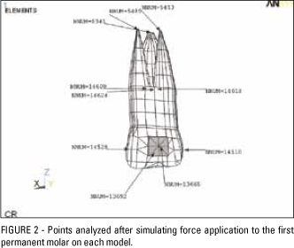
The computer simulations represented only the initial movement resulting from the 4N force (Newton) delivered to the first permanent molars, considering the presence of the second permanent molars. Measurements were made from the points marked on the root, crown and center of resistance region of the first permanent molar. The value of all points prior to force delivery was zero (Fig 2).
The initial movement, resulting from the force delivered by the headgear, caused deformation of the periodontal ligament, whose elastic modulus was 0.05 N/mm2 and Poisson's ratio 0.49. The force was considered static load23,28 to allow tooth movement in its respective alveolus, with a modulus of elasticity of 20,000 N/mm2 and Poisson's ratio of 0.30.7,23
RESULTS
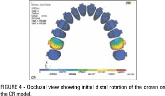
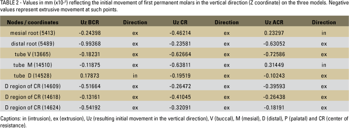
The initial distal movement of maxillary first molars (Ux) on the model in which the resultant of forces ran below the center of resistance (BCR) caused greater distal tipping in the crown than in the root, producing a tip back movement. In the center of resistance (CR) model, distal bodily movement occurred, causing displacement of the distal root as far as the middle third. On the model in which the resultant of forces ran above the center of resistance (ACR), the displacement was greater in the distal root, tipping the tooth forward (Fig 3). All models, in occlusal view, tended initially towards distal crown rotation (Fig 4). However, this movement was very small on the CR model.
Results for the vertical direction (Uz) revealed that all models exhibited extrusion, which was higher on the ACR model. The CR model exhibited mild extrusion at all points, unlike BCR and ACR, which showed slight intrusion at distal and mesial points of the crown, respectively.
The values shown in Table 1 and 2 confirmed the initial molar displacement in each HG model, displaying its direction and orientation at each maxillary molar point.
DISCUSSION
Finite element method (FEM) was employed through variational formulation and the mechanical properties of organic tissues and orthodontic materials were obtained in the orthodontic literature,7,19,23,28 which enabled the characterization of the elements and the geometry of the body using numerical modules.
The effects of forces applied to the first molars examined in these models are virtually the same as those observed in clinical practice. Figure 4 illustrates the differences that occur at key points (root and crown) of the first permanent molar on the BCR and ACR force line models in the anteroposterior orientation (X coordinate). A uniform distal movement can also be observed on the CR model. Points 1 and 2 are located in the mesiobuccal and palatal roots of the molar. Points 3 and 4 are in the distal and mesial surfaces of the buccal tube bonded to the molar crown. Thus, reverse tipping can be noted, depending on the force lines of the two models (BCR and ACR).
Melsen and Dalstra18 demonstrated, by superimposing patients' X-rays, that the type of tooth movement that occurs while wearing headgear with a downward or upward outer bow angulation was dependent on the force action line in both groups. Patients who wore headgear with a downward angulation displayed extrusion and distally tipped crowns, while those with an upward angulation exhibited translatory (bodily) movement.18 The authors used the center of resistance as a reference, as in the present study, which found distally tipped crowns on the BCR model, distally tipped roots on the ACR model and bodily movement on the CR model.

Extrusion evidence found in the three models can be explained by the point of origin of force application, which was located low in the patients' cervical region.20,29 This movement, however, is not necessarily undesirable, since in some cases, e.g., patients with a reduced lower facial third, extrusion is expected, given its impact on their facial profile as a whole.24,29 Care should be taken in cases where it is necessary to raise the outer bow in order to achieve an action line that is better suited for the effect desired in the molar, since any elevation in the outer bow will increase the extrusive component (Table 2, reference node tube V).
Ashmore et al2 described the movement of first permanent molars during treatment with headgear (combined traction) on plaster models analyzed in 3D. The results showed little extrusion due to the fact that the high-pull force used in their study ran through the CR, producing bodily movements. Despite the reduced amount of movement and the cervical traction, the same results were found in this study: uniform distal movement of the crown and root, and mild extrusion on the CR model.
Oosthuizen et al20 reported that the center of resistance of the maxillary first molar is positioned approximately at the trifurcation of the roots, at the mid-height of the cervical third. When the action line of a force does not go through the center of resistance, the tooth being moved tips under its center of rotation, i.e., depending on the position of this line, the molar will display a tipping movement.20 The mechanical function explained above further reinforces the clinical findings as well as the findings of this study, based on finite elements.
The center of resistance of the tooth or skeletal unit to be moved provides the rationale for the organization of a force system.27 The effects caused by varying the outer bow can also be applied to orthopedic movements since the reasoning behind the distribution of forces through vectors is similar. The only difference lies in the location of the center of resistance.
According to Klein's superimposition cephalometric studies, molar movement could be observed free from the influence exerted by the patient's growth15. He found that in 17 of 23 cases molars experienced distal bodily movement.15 Unlike Piva et al22; Schiavon Gandini et al.24 demonstrated in cephalometric radiographs that even in cases where the maxilla was rotated downwards, the axial inclination of the molar remained unchanged and there was greater distal tipping of the root, even when the force line ran through the center of resistance. Schiavon Gandini et al24 standardized outer bow angulation while Klein15 resorted to cervical traction only.
Several authors have stated that it is possible to prevent undesirable displacements, such as mesial or distal crown tipping, through changes in the outer bow of the headgear ,by either raising or lowering it, but that depends more on the operator than on the patient.15,16 Traction line angulation can be changed only by varying outer bow angle and length.20,25 It is possible, however, with such changes, to cause extrusive movements that undermine vertical control mechanics, especially when the outer bow is raised to correct distal molar tipping (tip back). In this situation, it is advisable to employ combined traction.
Similarly to the findings of this study, Haas believes that the tendency displayed by molars to rotate around their own axis in the lingual direction only occurs because force application derives from a low position in the outer bow (patient's cervical region). He therefore proposes that the inner bows of the headgear be expanded, thereby improving molar positioning.12 Other authors recommend the use of a removable palatal bar to control vertical movement and correct undesirable rotations and torques during treatment.11,13,30 Besides, rectangular archwires can obviously be used to control torque when a patient is in this treatment phase.
Piva et al22 suggest that 3D studies be conducted given the limitations of radiography, which does not disclose pure molar movement through overlays (superimposition) due to changes in growing patients. Thanks to the use of the finite element method (FEM), the results of this research succeeded in reflecting maxillary molar movement in isolation by varying the outer bows of the headgear.
CONCLUSIONS
It was shown that the use of cervical-traction headgear causes extrusive and distal movement. Force line orientation is important to control maxillary molar movement, which can be translatory (bodily), tip back or tip forward, when distal movement occurs through the use of a headgear. Determining this approach depends on the clinical situation and on orthodontic treatment planning.
REFERENCES
- 1. Armstrong MM. Controlling the magnitude, direction, and duration of extraoral force. Am J Orthod. 1971 Mar;59(3):217-43.
- 2. Ashmore JL, Kurland BF, King GJ, Wheeler TT, Ghafari J, Ramsay DS. A 3-dimensional analysis of molar movement during headgear treatment. Am J Orthod Dentofacial Orthop. 2002 Jan;121(1):18-29.
- 3. Baumrind S, Korn EL, Isaacson RJ, West EE, Molthen R. Quantitative analysis of the orthodontic and orthopedic effects of maxillary traction. Am J Orthod. 1983 Nov;84(5):384-98.
- 4. Burkhardt DR, McNamara JA Jr, Baccetti T. Maxillary molar distalization or mandibular enhancement: a cephalometric comparison of comprehensive orthodontic treatment including the pendulum and the Herbst appliances. Am J Orthod Dentofacial Orthop. 2003 Feb;123(2):108-16.
- 5. Cattaneo PM, Dalstra M, Melsen B. The transfer of occlusal forces through the maxillary molars: a finite element study. Am J Orthod Dentofacial Orthop. 2003 Apr;123(4):367-73.
- 6. Chang YI, Shin SJ, Baek SH. Three-dimensional finite element analysis in distal en masse movement of the maxillary dentition with the multiloop Edgewise archwire. Eur J Orthod. 2004 Jun;26(3):339-45.
- 7. Chen WP, Lee BS, Chiang YC, Lan WH, Lin CP. Effects of various periodontal ligament elastic moduli on the stress distribution of a central incisor and surrounding alveolar bone. J Formos Med Assoc. 2005 Nov;104(11):830-8.
- 8. Gautam P, Valiathan A, Adhikari R. Craniofacial displacement in response to varying headgear forces evaluated biomechanically with finite element analysis. Am J Orthod Dentofacial Orthop. 2009 Apr;135(4):507-15.
- 9. Ghafari J, Shofer FS, Jacobsson-Hunt U, Markowitz DL, Laster LL. Headgear versus function regulator in the early treatment of Class II, Division 1 malocclusion: A randomized clinical trial. Am J Orthod Dentofacial Orthop. 1998 Jan;113(1):51-61.
- 10. Grando G, Young AA, Vedovello M Filho, Vedovello SA, Ramirez-Yañez GO. Prevalence of malocclusions in a young Brazilian population. Int J Orthod Milwaukee. 2008 Summer;19(2):13-6.
- 11. Gündüz E, Zachrisson BU, Hönigl KD, Crismani AG, Bantleon HP. An improved transpalatal bar design. Part I. Comparison of moments and forces delivered by two bar designs for symmetrical molar derotation. Angle Orthod. 2003 Jun;73(3):239-43.
- 12. Haas AJ. Headgear therapy: the most efficient way to distalize molars. Semin Orthod. 2000 Jun;6(2):79-90.
- 13. Ingervall B, Hönigl KD, Bantleon HP. Moments and forces delivered by transpalatal arches for symmetrical first molar rotation. Eur J Orthod. 1996 Apr;18(2):131-9.
- 14. Jacobson A. A key to the understanding of extraoral forces. Am J Orthod. 1979 Apr;75(4):361-86.
- 15. Klein PL. An evaluation of cervical traction on the maxilla and the upper first permanent molar. Angle Orthod. 1957 Jan;27(1):61-8.
- 16. Kloehn SJ. Orthodontics-force or persuasion. Angle Orthod. 1953 Jan;23(1):56-65.
- 17. Melsen B. Effects of cervical anchorage during and after treatment: an implant study. Am J Orthod. 1978 May;73(5):526-40.
- 18. Melsen B, Dalstra M. Distal molar movement with Kloehn headgear: is it stable? Am J Orthod Dentofacial Orthop. 2003 Apr;123(4):374-8.
- 19. Natali AN, Pavan PG, Scarpa C. Numerical analysis of tooth mobility: formulation of a non-linear constitutive law for the periodontal ligament. Dent Mater. 2004 Sep;20(7):623-9.
- 20. Oosthuizen L, Dijkman JF, Evans WG. A mechanical appraisal of the Kloehn extraoral assembly. Angle Orthod. 1973 Jul;43(3):221-32.
- 21. Pavlick CT Jr. Cervical headgear usage and the bioprogressive orthodontic philosophy. Semin Orthod. 1998 Dec;4(4):219-30.
- 22. Piva LM, Brito HH, Leite HR, O'Reilly M. Effects of cervical headgear and fixed appliances on the space available for maxillary second molars. Am J Orthod Dentofacial Orthop. 2005 Sep;128(3):366-71.
- 23. Rees JS, Jacobsen PH. Elastic modulus of the periodontal ligament. Biomaterials. 1997 Jul;18(14):995-9.
- 24. Schiavon Gandini MR, Gandini LG Jr, Da Rosa Martins JC, Del Santo M Jr. Effects of cervical headgear and Edgewise appliances on growing patients. Am J Orthod Dentofacial Orthop. 2001 May;119(5):531-8.
- 25. Shimizu RH, Ambrosio AR, Shimizu IA, Godoy-Bezerra J, Ribeiro JS, Staszak KR. Princípios biomecânicos do aparelho extrabucal. Rev Dental Press Ortod Ortop Facial. 2004 nov-dez;9(6):122-56.
- 26. Stafford GD, Caputo AA, Turley PK. Characteristics of headgear release mechanisms: Safety implications. Angle Orthod. 1998 Aug;68(4):319-26.
- 27. Stockli PW, Teuscher UM. Ortopedia combinada com ativador e extra-bucal. In: Graber RL, editor. Ortodontia: princípios e técnicas atuais. Rio de Janeiro: Guanabara Koogan; 1994. p. 400-65.
- 28. Sung SJ, Baik HS, Moon YS, Yu HS, Cho YS. A comparative evaluation of different compensating curves in the lingual and labial techniques using 3D FEM. Am J Orthod Dentofacial Orthop. 2003 Apr;123(4):441-50.
- 29. Uçem TT, Yüksel S. Effects of different vectors of forces applied by combined headgear. Am J Orthod Dentofacial Orthop. 1998 Mar;113(3):316-23.
- 30. Wise JB, Magness WB, Powers JM. Maxillary molar vertical control with the use of transpalatal arches. Am J Orthod Dentofacial Orthop. 1994 Oct;106(4):403-8.
Analysis of initial movement of maxillary molars submitted to extraoral forces: a 3D study
Publication Dates
-
Publication in this collection
11 Nov 2010 -
Date of issue
Oct 2010
History
-
Received
Feb 2009 -
Accepted
Aug 2009