Abstract
A novel method is presented to design the configuration of pumping lasers of Raman amplifiers using a multi-objective particle swarm optimizer. The goal is to obtain the pump laser wavelengths and powers that maximize the amplifier on-off gain, while maintaining the flatness of the gain over the used bandwidth. We used an algorithm called Multiple Objective Particle Swarm Optimization with Crowding Distance and Roulette Wheel to generate the non-dominated solutions, considering the average on-off gain and the ripple of the amplifier over the transmission bandwidth as the objectives in the optimization process. We designed amplifiers using three, four and five pump lasers. The experimental results showed that our proposal was able to design Raman amplifiers with a gain ripple lower than 0.2 dB and with an average on-off gain around 16.7 dB, when 20 signal channels and a total pump power of 1 W were considered. Moreover, we demonstrated that it is possible to allow the decision maker to choose among many possible non-dominated solutions depending on the application requirements.
Optical Amplifiers; Raman Amplification; Multi-objective Optimization; Particle Swarm Optimization
Design of distributed optical-fiber raman amplifiers using multi-objective particle swarm optimization
Carmelo J. A. Bastos-FilhoI; Elliackin M. N. FigueiredoI; Joaquim F. Martins-FilhoII; Daniel A. R. ChavesII; Marcelo E. V. SegattoIII; S. CaniIII; Maria J. PontesIII
IPolytechnic School of Pernambuco, University of Pernambuco, Recife, Brazil, Email: carmelofillho@ieee.org
IIDepartment of Electronics and Systems, Federal University of Pernambuco, Recife, Brazil, Email: jfmf@ufpe.br
IIIElectrical Engineering Department, Federal University of Espírito Santo, Vitória, Brazil, Email: segatto@ele.ufes.br
ABSTRACT
A novel method is presented to design the configuration of pumping lasers of Raman amplifiers using a multi-objective particle swarm optimizer. The goal is to obtain the pump laser wavelengths and powers that maximize the amplifier on-off gain, while maintaining the flatness of the gain over the used bandwidth. We used an algorithm called Multiple Objective Particle Swarm Optimization with Crowding Distance and Roulette Wheel to generate the non-dominated solutions, considering the average on-off gain and the ripple of the amplifier over the transmission bandwidth as the objectives in the optimization process. We designed amplifiers using three, four and five pump lasers. The experimental results showed that our proposal was able to design Raman amplifiers with a gain ripple lower than 0.2 dB and with an average on-off gain around 16.7 dB, when 20 signal channels and a total pump power of 1 W were considered. Moreover, we demonstrated that it is possible to allow the decision maker to choose among many possible non-dominated solutions depending on the application requirements.
Index Terms: Optical Amplifiers, Raman Amplification, Multi-objective Optimization, Particle Swarm Optimization.
I. INTRODUCTION
The deployment of Wavelength Division Multiplexing (WDM) systems resulted in a huge demand to develop broad-band devices. Besides, the ever increasing traffic demand generated by the new Internet and video-based services has driven the telecommunication market to expand the systems in order to use other transmission bands [1]. Although Erbium-Doped Fiber Amplifiers (EDFA) have been successfully used in WDM systems since the 1990's, EDFAs cannot provide flat gain over the entire S+C+L transmission bands (1460nm - 1610nm).
Optical Raman Fiber Amplifiers (RFA) have been widely investigated because of some promising features, such as low noise figure, wide and tunable amplification bandwidth, and low nonlinearity [2] [3]. Moreover, RFAs can allow Raman amplification through the entire transmission fiber [4].
However, different channels in a WDM system can be amplified by different gain due to the flatless nature of the Raman gain spectrum. This effect can be mitigated using multiple pumps lasers at slightly different wavelengths. In this case, each pump provides a non-uniform gain, but the gain spectra for different pumps can overlap partially. Therefore, a suitable choice of the wavelength and of the power of each pump laser can generate a nearly flat gain profile over a wide wavelength range [5]. In order to provide a wide and flat gain bandwidth, the power and the wavelength of each pump must be carefully chosen [2].
In 1999, for example, an amplification bandwidth of 100 nm with a ripple lower than 1 dB, using 12 pump lasers was demonstrated [6]. However, the complex nonlinear interaction caused by the Raman effect among pumps and signals over a distributed RFA employing multiple-pumps turns the adjustment of the powers and the wavelengths of the pumps a difficult task [3]. Because of this, some global optimization methods have been proposed to solve this problem such as: simulated annealing [2]; neural networks [7]; particle swarm optimization and genetic algorithm [8]. However, despite the conflicting nature between gain and ripple, to the best of our knowledge, no multi-objective optimization approach was applied to solve this problem so far.
Here we propose a multi-objective particle swarm optimizer to proper select the wavelengths and the powers of the pumps, in order to balance the trade-off between gain and ripple. We propose to use the Multiple Objective Particle Swarm Optimization approach using Crowding Distance and Roulette Wheel (MOPSO-CDR) [9]. We considered counter-pumped distributed Raman amplifiers since they can improve the noise characteristics, mitigate fiber nonlinear effects and improve the optical signal-to-noise ratio (OSNR) [1].
The rest of this paper is organized as follow. In Section II some Raman amplifier concepts are presented. In Section III, the MOPSO-CDR algorithm is briefly described, while in Sections IV and V the simulation setup and the results are presented. Finally, we give our conclusions in Section VI.
II. RAMAN FIBER AMPLIFIERS
Optical Raman Fiber Amplifiers present several merits such as wider amplification bandwidth, low noise, flexible center wavelength, and higher power budget capacity, when compared to doped fiber amplifiers. Although multiple pumps are necessary to allow spectral flattened gain amplification, the technological advances in high-power laser diodes allow the implementation of such amplifiers at competitive prices.
RFAs are commonly designed as lumped Raman amplifier or distributed Raman amplifier configurations [10]. Pumping schemes in those amplifiers can go forward and/or backward in relation to the propagating signals. One advantage of implementing lumped over distributed amplifiers is to avoid the downsides of high pump powers propagating in the transmission fiber, which results from the pump power extending along the entire fiber link in the distributed configuration [4; 5].
Theoretical Raman gain as well as noise impairments are ordinarily evaluated using numerical simulation methods. A closed analytical solution to this problem is therefore a contribution in its own right since it provides insights into the gain dependence on the physical parameters of the Raman amplifier. Moreover, approximated analytical expressions may allow to obtain accurate results in a reduced computation time. Such analytical expressions are of particular interest in the intricate optimization of broadband Raman amplifiers, where several pumps have to be properly selected, regarding their wavelengths and intensities, so as to achieve multi-objective functions such as minimal ripple and maximal gain.
The evolution of the powers of the signals and pumps are governed by the nonlinear coupled equations described in [4], [10]. In this paper we will use the analytical simulator developed by Cani et al. [10] and presented in Section IV.D.
III. MULTI-OBJECTIVE PARTICLE SWARM OPTIMIZATION WITH CROWDING DISTANCE AND ROULETTE WHEEL
The Multiple Objective Particle Swarm Optimization with Crowding Distance and Roulette Wheel (MOPSO-CDR) algorithm was proposed by Santana et al. in 2009 [9] and is based on a well known optimization technique called Particle Swarm Optimization (PSO) [11].
In general, PSO algorithms are suitable to tackle problems with continuous decision variables in high dimensional spaces, as is the present case, where we are dealing with many lasers and the wavelengths and powers can vary continuously. This particular algorithm has been chosen because it led to a better performance than other PSO-based approaches [9].
MOPSO-CDR uses a diversity mechanism called crowding distance to select the social leader (gBest) and the cognitive leader (pBest) to guide the particles during the search process. pBest and gBest are the best positions obtained by the particle and the swarm during the search process so far. The same mechanism is used to remove solutions from the external archive. The pseudocode of the MOPSO-CDR is presented in Algorithm I. The following subsections show the main features of the MOPSO-CDR.
A. External Archive (EA)
The External Archive (EA) is a repository to store the non-dominated solutions found during the search process so far. A solution a dominates another solution b, if a presents a better fitness values for all the objective functions than b. If a is better in one objective function and is not worse in the others, we say a weakly dominates b.
The MOPSO-CDR has to decide whether a certain solution should be added to the EA or not. At each iteration, non-dominated solutions of the swarm population are compared with the solutions of the EA. The candidate solutions that are not dominated by the current solutions within the EA must be included in the EA. After this, the dominated solutions within the EA must be removed. Besides, the EA has a maximum number of solutions. If the size of the EA is exceeded at the end of the iteration, solutions in more crowded regions are removed from the EA using the crowding distance criterion.
B. Selection of the Social Leader
In the MOPSO-CDR, the candidates to be a social leader are the current solutions stored in the EA. The probability to choose a solution stored in the EA is proportional to its crowding distance. The crowding distance of a solution corresponds to the semi-perimeter of the rectangle that connects the neighbor solutions within the EA. After this, the solutions of the EA are sorted by using crowding distance (CD) before the next iteration. For each particle, a social leader is selected for each iteration by applying a roulette wheel in the EA considering the CD. One can note that the solutions in less crowded regions have more chance to be selected.
C. Updating the Cognitive Leader
In the MOPSO-CDR, the cognitive leader of each particle is updated if the new position of the particle dominates the current pBest. If the new position and the pBest are incomparable, the choice is made using the EA. The MOPSO-CDR searches for solutions in the EA with minimum Euclidean distance for the pBestand for the new position. If the closer solution to the new position in the EA is in a less crowded region than the closer solution to the pBest in the EA, the pBestwill be updated with the new position of the particle. Otherwise, the old pBest remains.
D. Turbulence Operator
The turbulence operator of MOPSO-CDR is the same used in the MOPSO [12] and it is applied at each iteration with a bounded influence. The turbulence operator performs a local search toward the current position of the particle. If the new position dominates the position before the turbulence, the position is updated. Otherwise, the old position remains.
In the beginning of the algorithm execution, all particles of the swarm are affected by this operator. As the number of iterations increases, the percentage of affected particles decreases.
IV. EXPERIMENTAL SETUP
In order to allow the MOPSO-CDR to be used to design Raman amplifiers, we had to define the input parameters (decision variables) and the objectives of the problem. The wavelengths and the power of the pump lasers were defined as input parameters. The selected objectives were the average on-off gain and the ripple of the gain over the transmission bandwidth. An analytical simulator was used to evaluate the average on-off gain and the ripple. This simulation tool is based on the analytical model for the evolution of signal and pump powers along the optical fiber. The details are described in Section IV-D. Fig. 1 illustrates the communication between the MOPSO-CDR optimizer and the Analytical Simulator.
We performed experiments to design Raman amplifiers with 3, 4 and 5 pump lasers. All the amplifiers are distributed and use a counter-propagating pump scheme in a single-mode fiber with a length of 75 km. The total pump power must be equal or below 1 W. Other aspects concerning the experimental setup are detailed below.
A. The Selection of the Objectives
We used two goals in our experiments: minimize the ripple and maximize the average on-off gain. The on-off gain is the gain provided by the amplifier to the signal when the pumps are turned on after subtracting the fiber link attenuation. The average on-off gain is simply the arithmetic mean value of the on-off gains for each signal. The ripple is the difference between the maximum on-off gain and minimum on-off gain, considering all the transmission signals.
B. The Representation of the Particles
Each particle consists of a vector containing the wavelengths and powers of the pumps. Considering an amplifier with n pumps, the particle has 2n positions, where the n first elements correspond to the wavelengths, while the remaining elements correspond to the power levels. Table I shows an example of representation for a particle when three pumps are considered. As shown in this table, the first pump has wavelength equal to λ1 and power equal to P1, the second pump has wavelength equal to λ2 and power equal to P2, and so on. The wavelengths can vary continuously within the interval from 1410 nm to 1470 nm, while the powers can vary between 100 mW and 1000 mW per pump laser.
C. Parameters for the MOPSO-CDR
In the simulations, we used 20 particles, mutation rate equal to 0.5 (the mutation is used to perform a local search around gbest), maximum number of solutions in the EA equal to 200, c1 and c2 are the acceleration constants of the cognitive and the social terms of the velocity equation, respectively, and are equal to 1.49445. ω is the inertia factor and weights the previous value of the velocity in the velocity equation. ω decreases linearly from 0.4 to 0 along the iterations. The maximum number of iterations is 1000. These values were defined based on the previous experiments in benchmark functions [9].
D. Analytical Simulator
The Analytical Simulator is a computational simulation tool for the analysis of multichannel optical communication systems with Raman amplifiers with multiple pumps. The simulator is based on an approximate analytical model of the evolution of pumps and signals along the optical link proposed by Cani et al. [10]. The objective of this simulator is to evaluate the gain achieved by the signal channel due to the presence of a distributed Raman amplifier in a single-mode fiber with one or more pumps.
The input parameters of the simulator are:
-
The number of laser pumps with the respective wavelengths and powers. The wavelengths can vary between 1430 nm and 1470 nm and the power can vary between 0 W and the total maximum power divided by the number of laser pumps;
-
The number of signal channels with the respective wavelengths. In the experiments, we used 20 WDM signal channels with 100 GHz of separation in the C band between 1545.32 nm and 1560.61 nm;
-
The Polarization Factor of the pump lasers (PF). The gain provided by the Raman effect depends on the polarizations of the signal and the pumps. For long optical fibers typically used in transmission systems, the polarization between pump and signal can vary arbitrarily between parallel and perpendicular. In the Analytical Simulator, PF = 1 if the polarization between pump and signal is maintained, and PF = 2 if the polarization varies as the signals and the pumps propagate through the optical fiber [10]. In the experiments, we assumed PF = 2.
The outputs provided by the simulator are:
-
Average on-off gain: The on-off gain is defined as the ratio between the signal power at the end of the link with pump and without pump. The average on-off gain is the mean of the on-off gains for all the signal channels;
-
Ripple: Each signal has an on-off gain, which is evaluated by considering the other signals and the pumps. The Ripple is the difference between the maximum on-off gain and the minimum on-off gain achieved by the signal channels.
E. Metrics to Evaluate the Quality of the Pareto Fronts
There are some metrics that can be used to measure the quality of the Pareto Fronts. The Pareto Front is the set of the obtained non-dominated solutions. The following metrics are used in this paper: Spacing, Maximum spread and Coverage. Each metric highlights a different aspect of the Pareto Front.
1) Spacing (S): Proposed by Schott in [13], it estimates the diversity for the achieved Pareto Front. S is evaluated by computing the relative distance between adjacent solutions of the Pareto Front, as follows,

where n is the number of non-dominated solutions, di is the distance between adjacent solutions to the solution i, and  is the average distance between the adjacent solutions. S=0 means that all the solutions of the Pareto Front are equally spaced.
2) Maximum Spread (MS): Proposed by Zitzler et al. [14], it evaluates the maximum extension covered by the non-dominated solutions in the Pareto front. MS is evaluated by

where n is the number of solutions in the Pareto front and M is the number of objectives.
3) Coverage (C): Proposed by Zitzler et al. [15], it is evaluated by

where A and B are two sets of non-dominated solutions. The value C(A,B)=1 means that all solutions in B are weakly dominated by A. On the other hand, C(A, B)=0 means that none of the solutions in B are weakly dominated by A.
One should note that both C(A, B) and C(B, A) have to be evaluated, since C(A,B) is not necessarily equal to 1-C(B,A). If 0<C(A,B)<1 and 0<C(B,A)<1, then neither A weakly dominates B nor B weakly dominates A. In this case, the sets A and B are incomparable, thus meaning that A is not worse than B and vice-versa.
V. SIMULATION RESULTS
In this section we present some simulation results considering 3 pump lasers (subsection V-A), 4 pump lasers (subsection V-B) and 5 pump lasers (subsection V-C).
A. Results for 3 pump lasers
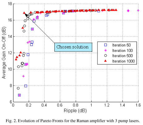
We first run the MOPSO-CDR algorithm in order to optimize the Raman amplifier with 3 pumps. Fig. 2 illustrates the evolution of Pareto Fronts for the iterations 50, 100, 500 and 1000. One can notice that the Pareto Fronts are quite close to each other for the iterations 500th and 1000th.
Table II shows the metrics used to compare the Pareto Fronts. We ran 30 trials and presented the mean value and standard deviation (in parenthesis) for each case. The Coverage was evaluated in relation to the previously collected Pareto Front, i.e. the Coverage at the 100th iteration was compared to the Pareto front at the 50th iteration. The high values for the Coverage indicate that the algorithm evolved along the iterations.
We chose the solution pointed at in Fig. 2 to design the Raman amplifier with 3 pump lasers. This solution represents an amplifier with average on-off gain around 16.86 dB and ripple around 0.141 dB. Table III presents the wavelengths and the powers for the pump lasers.
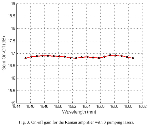
After that, we performed a simulation using the Analytical Simulator for an optical link with 20 WDM signal channels considering the Raman amplifier with the pumps showed in Table III. Fig. 3 shows the on-off gains achieved by the Analytical Simulator for all signal channels. As one can see, Ripple < 0.2 dB, which means that all signal channels achieved almost the same on-off gain, all of them exceeding 16.5 dB.
We also performed a test rounding the wavelengths to integer numbers in order to check the sensibility of the result. We observed that by doing this that the ripple is not affected significantly.
B. Results for 4 pump lasers
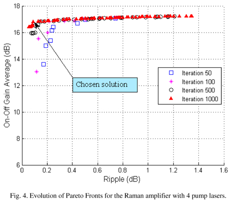
Now we apply the same methodology to design of the amplifier with 4 pump lasers. The evolution of the Pareto Front is shown in Fig. 4. As in the previous experiment, we evaluated the metrics for the Pareto Fronts and the results are summarized in Table IV.
Though most of the comments done for the case with 3 pump lasers can be extended to here, one can notice that the Pareto Fronts achieved for 4 pump lasers are quite better than the ones achieved for 3 pump lasers, mainly in the kink.
We chose the solution pointed at in Fig. 4 to design the Raman amplifier with 4 pump lasers. This solution represents an amplifier with average on-off gain around 16.8 dB and ripple around 0.089 dB. Table V presents the wavelengths and the powers for the pump lasers.
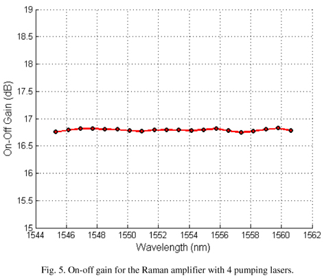
Fig. 5 shows the on-off gains achieved by the Analytical Simulator for all signal channels. Furthermore, all signal channels achieved almost the same on-off gain, all of them exceeding 16.5 dB.
C. Results for 5 pump lasers
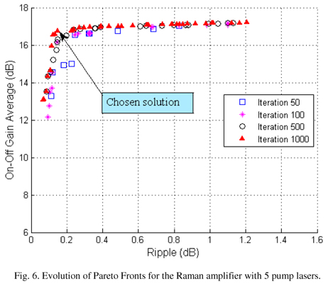
We performed the optimization to design the amplifier with 5 pump lasers. The evolution of the Pareto Front is shown in Fig. 6. As in the previous experiment, we evaluated the metrics for the Pareto Fronts and the results are summarized in Table VI.
We chose the solution pointed in Fig. 6 to design the Raman amplifier with 5 pump lasers. This solution represents an amplifier with average on-off gain around 16.73 dB and ripple around 0.15 dB.
Finally, we increased the number of channels to analyze the scalability of the algorithm. We performed the optimization to design the amplifier with 5 pump lasers for 40 signal channels covering the entire C band. The evolution of the Pareto Front is shown in Fig. 8. The ripple was slightly increased, as expected.
VI. CONCLUSIONS
We proposed in this paper a novel method to define the pump specifications for Raman fiber amplifiers. We used a multi-objective particle swarm optimization algorithm known as MOPSO-CDR to design the Raman amplifier. Configurations of Raman fiber amplifiers with 3, 4 and 5 pump lasers were generated and demonstrated. This method allows one to design high performance Raman amplifiers with high gain, low ripple, and wide bandwidth for WDM systems. One should notice that better results could be achieved if more pump lasers are used, but it will also increase the total cost of the amplifier. The method achieved better results in terms of ripple when compared to a simple genetic algorithm, which achieved a ripple around 1 dB for similar conditions [16]. One can observe that the MOPSO-CDR is suitable for this type of application since it presents a fast convergence and can easily deal with more than one objective function. Besides, as future work, one can add a third objective in order to minimize the number of required pump lasers.
ACKNOWLEDGMENT
The authors thank the University of Pernambuco, Federal University of Pernambuco, Federal University of Espírito Santos, FACEPE, FAPES, CAPES and CNPq.
Received 28 March 2011; for review 11 April 2011; accepted 4 Aug. 2011
- [1] X. Liu and B. Lee, "Optimal design for ultra-broad-band amplifier," Journal of Lightwave Technology, vol. 12, pp. 34463455, 2003.
- [2] M. Yan, J. Chen, W. Jiang, J. Li, J. Chen, and X. Li, "Automatic design scheme for optical-fiber raman amplifiers backward-pumped with multiple laser diode pumps," IEEE Photonics Technology Letters, vol. 13, no. 9, pp. 948950, September 2001.
- [3] J. Zhou, J. Chen, X. Li, W. Jiang, and Y. Wang, "A novel pump adjustment method for wdm pumped optical raman amplifier," Optics Communications, vol. 248, pp. 407413, 2005.
- [4] J. Bromage, "Raman amplification for fiber communications systems," IEEE Journal of Lightwave Technology, vol. 22, no. 1, pp. 7993, January 2004.
- [5] C. Headley and G. P. Agrawal, Raman Amplification in Fiber Optical Communication Systems. San Diego, California, EUA: Elsevier Academic Press, 2005.
- [6] Y. Emori and S. Namiki, "100 nm bandwidth flat-gain raman amplifiers pumped and gain-equalised by 12-wavelength-channel wdm laser diode unit," Electronics Letters, vol. 35, no. 16, pp. 13551356, May 1999.
- [7] P. Xiao, Q. Zeng, J. Huang, and J. Liu, "A new optimal algorithm for multipump sources of distributed fiber Raman amplifier," IEEE Photonics Technology Letters, vol. 3, pp. 206208, 2003.
- [8] A. Mowla and N. Granpayeh, "Design of a flat-gain multipumped distributed fiber Raman amplifier by particle swarm optimization," J. Opt. Soc. Am. A, vol. 25, no. 12, pp. 30593066, December 2008.
- [9] R. A. Santana, M. R. Pontes, and C. J. A. Bastos-Filho, "A multiple objective particle swarm optimization approach using crowding distance and roulette wheel," in ISDA '09: Proceedings of the 2009 Ninth International Conference on Intelligent Systems Design and Applications. Pisa, Italia: IEEE, 2009.
- [10] S. Cani, L. de Calazans Calmon, M. Pontes, M. Ribeiro, M. Segatto, and A. Cartaxo, "An analytical approximated solution for the gain of broadband Raman amplifiers with multiple counter-pumps", Lightwave Technology, Journal of, vol. 27, no. 7, pp. 944 951, 2009.
- [11] J. Kennedy and R. Eberhart, "Particle swarm optimization," in Proceedings of IEEE International Conference on Neural Networks. Perth, Aust: IEEE, 1995, pp. 19451948.
- [12] C. Coello, G. Pulido, and M. Lechuga, "Handling multiple objectives with particle swarm optimization," IEEE Transactions on Evolutionary Computation, vol. 8, no. 3, pp. 256279, 2004.
- [13] J. Schott, "Fault tolerant design using single and multicriteria genetic algorithm optimization," PHD Thesis, Department of Aeronautics and Astronautics, Massachusetts Institute of Technology, Cambridge, Massachusetts, 1995.
- [14] E. Zitzler, K. Deb, and L. Thiele, "Comparison of multiobjective evolutionary algorithms: Empirical results," Evolutionary computation, vol. 8, no. 2, pp. 173195, 2000.
- [15] E.Zitzler and L.Thiele,"Multi-objective Evolutionary Algorithms: A Comparative case study and the strength Pareto approach," IEEE transactions on Evolutionary Computation, vol. 3, no. 4, pp. 257271, 1999.
- [16] G. C. M. Ferreira,"Análise e Otimização de Sistemas Ópticos com Amplificação Raman," Projeto de Graduação, Departamento de Engenharia Elétrica, UFES, 2008.
Publication Dates
-
Publication in this collection
09 Mar 2012 -
Date of issue
Dec 2011
History
-
Received
28 Mar 2011 -
Reviewed
11 Apr 2011 -
Accepted
04 Aug 2011