
Abstract
An efficient practical method for the electromagnetic (EM) fields reduction around transmitting stations has been developed. The project has been stimulated by the necessity to reduce the field levels in the vicinity of transmitting stations, including FM, UHF, cellular base stations and other radiocommunication services, to obey regulations concerning human protection against electromagnetic radiation. The main constraint in the optimization procedure is the requirement to preserve the radiated power ERP of a service in operation. The method joins accuracy with high efficiency, and is based on 3 stages procedure using the antenna numerical models of different levels of approximation. An example is given of its application to a real case of transmitting stations in which the levels of measured EM exceeded the safety limits.
Index Terms
antenna systems; human exposure assessment; non-ionizing radiation; electromagnetic fields (EMF); radiation limits; radiation patterns
Introduction
A practical problem often met in antenna techniques is the necessity to modify the electromagnetic fields (EMF) distribution generated by an antenna system. The problem can emerge due to various reasons, in particular due to requirements concerning the human protection against EMF radiation 11 ICNIRP, Guidelines for limiting exposure to time-varying electric, magnetic and electromagnetic field (up to 300 GHz), 1998,22 IEEE limits: IEEE Std C95.1 – 2005, IEEE Standard for Safety Levels with Respect to Human Exposure to Radio Frequency Electromagnetic Fields, 3 kHz to 300 GHz, October 2005.3 Polish regulations: Rozporzadzenie Ministra Srodowiska z dnia 30 pazdziernika 2003 r. w sprawie dopuszczalnych poziomow pol elektromagnetycznych w srodowisku oraz sposobow sprawdzania dotrzymania tych poziomow, Dz.U.2003.192.1883, Warsaw, 2003. Moreover, in some countries, like in Poland, there are local regulations in which the safety limits are much more restrictive than that mentioned above. There exists a social need to control the levels of emissions which is connected with some anxiety concerning the harmful effects of EMF on human health 66 J. C. Lin, Controversy over cellular mobile-telecommunication base-station-antenna installations, IEEE Antennas and Propagation Magazine, vol. 46, no.1, pp. 155-156, Feb. 2004 ,77 J. C. Lin, A research program on the human impact of wireless telecommunications and other electromagnetic-field-emitting systems, IEEE Antennas and Propagation Magazine, vol. 46,no. 6. pp. 161-163, Dec. 2004,88 J. C. Lin, Radio frequency exposure and safety associated with base stations used for personal wireless telecommunication, IEEE Antennas and Propagation Magazine, vol. 44, no. 1, pp. 180-183, Feb. 2002. This work deals with the problem and offers a method of EMF mitigation. No similar work is known to the authors.
The task is somewhat similar to characteristic synthesis but the difference is that we often deal with already existing system, and thus there are limited degrees of freedom of possible changes which can be implemented (the technical and economic limitations) 44 ITU-T Recommendation K.70: Mitigation techniques to limit human exposure to EMFs in the vicinity of radiocommunication stations, Geneva 2007.,55 F. Lewicki,Importance of antenna VRP in radiation protection consideration, Proceedings of XVII International Wroclaw Symposium on EMC, pp. 123 – 126, Wroclaw, Poland 2004.,1010 M. Kaluski, L. Stasierski, Electromagnetic field estimation in the vicinity of panel antenna system for FM and TV broadcasting, IEEE Trans. on Broadcasting, vol. 41, no 4, pp. 136-142, Dec. 19951111 B. Fourestié, J-C. Bolomey, T. Sarrebourse, Z Altman, J. Wiart, Spherical Near Field Facility for Characterizing Random Emissions, IEEE Trans. on Antennas and Propagation vol. 53, pp. 2582-2589, Aug. 2005,1515 Y. Adane, A. Gati, M.-F. Wong, C. Dale, J. Wiart, and V. F. Hanna, “Optimal modeling of real radio base station antennas for human exposure assessment using spherical-mode decomposition,” IEEE Antennas Wireless Propag. Lett., vol. 1, pp. 215–218, 2002.,2222 M. J. van Wyk, M. Bingle, and F. J. C. Meyer, “Antenna modeling considerations for accurate SAR calculations in human phantoms in close proximity to GSM cellular base station antennas,” Bioelectromagnetics, vol. 26, pp. 502–509, 2005.,2323 EN 50383, Basic standard for the calculation and measurement of electromagnetic field strength and SAR related to human exposure from radio base stations and fixed terminal stations for wireless telecommunication systems, CENELEC, Brussels, August 2002. . Since there is no rigorous mathematical method for that purpose the only choice is a human-assisted trial-and-error computational procedure which would, on the one hand, assure a sufficient accuracy and, on the other hand, be efficient enough. The problem is that the accuracy contradicts efficiency, i.e. the more accurate is the computational method the less efficient it is.
The proposed method is based on the computational analysis which uses the numerical models of different levels of complication and accuracy. Suppose we meet in practice a situation where the violation of safety limits for EM field has been detected, via control measurements, somewhere around a transmitting station. Some protective measures must be taken in order to make the station compliant with environmental protection regulations. At the first stage of the proposed method the violation has to be confirmed numerically, preferably with the use of relatively simple but accurate enough numerical model. For that purpose we use a synthetic model [10], in which the radiation characteristics of elementary sources (antenna panels or patches) are evaluated by direct numerical solution of Maxwell’s equations. At this stage also the source of radiation responsible for the violation is identified. In the next step (the main one) a modification of the identified antenna system has to be made to achieve the wanted reduction of the field levels. The full synthetic model used previously, although relatively simple, is not efficient enough to do this task, i.e. to perform many trials in the trial-and-error procedure and find the necessary modification. Thus, in that stage we apply a point source model being a simplified synthetic model in which the far field (for the whole system) and the scalar wave approximations are used. The Vertical Radiation Pattern (VRP) of the antenna system [5] is modified in order to find its new shape that will give the proper radiation levels in the points of interest. The shape of the VRP is crucial because it determines the distribution of the field level as a function of distance to the antenna tower. The main constraint in the procedure of modification is that the coverage area of the service must be kept unchanged and that the excitations above the safety limits in some other points should not appear. With this method the effect of modifications on the field distribution can be observed immediately in real time of simulation. Finally, the verification stage is necessary with a more accurate model. Here, the full synthetic model is used again to check if the emission from the modified antenna system, when contributing to the cumulative exposure, will be compliant with exposure limits. If some violations are still present the whole procedure must be repeated.
The proposed procedure is very efficient, flexible, and allows finding the necessary modifications so that they meet the economic and technical requirements. It has been successfully used and tested in practice. Below we will describe the method in more detail on the example of its application to a real life problem.
Description of the problem
The violation of safety limits was detected via control measurements in certain points around a transmitting station located on the top of a local mountain (Radio and TV Transmission Station on Swiety Krzyz Mountain, Kielce, Poland, see Fig. 1). The transmitting station was rather typical and contained a number of transmitting systems operating on many frequencies 77 J. C. Lin, A research program on the human impact of wireless telecommunications and other electromagnetic-field-emitting systems, IEEE Antennas and Propagation Magazine, vol. 46,no. 6. pp. 161-163, Dec. 2004,1414 A. Faraone, R. Y.-S. Tay, K. H. Joyner, and Q. Balzano, “Estimation of the average power density in the vicinity of cellular base-station collinear array antennas,” IEEE Trans. Veh. Technol., vol. 49, no. 3, pp. 984–996, May 2000.,1616 R. Cicchetti and A. Faraone, “Estimation of the peak power density in the vicinity of cellular and radio base station antennas,” IEEE Trans. Electromagn. Compat., vol. 46, no. 2, pp. 275–290, May 2004.1717 J. Cooper, B. Marx, J. Buhl, and V. Hombach, “Determination of safety distance limits for a human near a cellular base station antenna, adopting the IEEE Standard or ICNIRP Guidelines,” Bioelectromagnetics, vol. 23, no. 6, pp. 429–443, 2002.. The following services were in operation:
-
FM broadcast with total ERP 545 kW (3x120 kW+3x60 kW+5kW),
-
UHF TV broadcast with transmitted power ERP 1000 kW and 870 kW (two TV channels)
-
Two GSM 900 base stations (3 sectors with ERP on the level of 500 W to 1 kW each)
-
Two GSM 1800 base stations (3 sectors with ERP on the level of 500 W to 1 kW each)
-
Fixed point to point services (about 22 links in the bands 7 GHz – 23 GHz)
-
Radiocommunication services in the band 160 MHz (10 transmitting antennas)
-
Radiocommunication systems in the band 450 MHz (4 transmitting antennas)
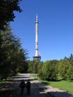
Fig. 1. Radio and TV Transmission Station on Swiety Krzyz (‘Saint Cross’) mountain, Kielce, Poland
All FM emissions were from one antenna system consisting of 10 bays and 5 faces of typical panels (2 dipoles with screen), operating in horizontal polarization and mounted on the concrete antenna tower at a height of 95 m above the ground level. On the top (100 m agl) the UHF antenna system was mounted consisting of 16 bays and 4 faces of the typical UHF panel (4 dipoles with screen). The GSM base stations, radiocommunication and point-to-point services consist typically of one panel or Yagi or dish antennas.
The EMF distribution in the vicinity of the antenna tower had a complex structure with many components of different frequencies and different field strengths, varying from point to point 44 ITU-T Recommendation K.70: Mitigation techniques to limit human exposure to EMFs in the vicinity of radiocommunication stations, Geneva 2007.,55 F. Lewicki,Importance of antenna VRP in radiation protection consideration, Proceedings of XVII International Wroclaw Symposium on EMC, pp. 123 – 126, Wroclaw, Poland 2004.,77 J. C. Lin, A research program on the human impact of wireless telecommunications and other electromagnetic-field-emitting systems, IEEE Antennas and Propagation Magazine, vol. 46,no. 6. pp. 161-163, Dec. 200499 O. P. Ghandi, An on site dosimetry system for safety assessment of wireless base stations using spatial harmonic components, IEEE Trans. on Antennas and Propagation, vol. 51, no. 4, pp. 840-847, April 2003,1414 A. Faraone, R. Y.-S. Tay, K. H. Joyner, and Q. Balzano, “Estimation of the average power density in the vicinity of cellular base-station collinear array antennas,” IEEE Trans. Veh. Technol., vol. 49, no. 3, pp. 984–996, May 2000.,1616 R. Cicchetti and A. Faraone, “Estimation of the peak power density in the vicinity of cellular and radio base station antennas,” IEEE Trans. Electromagn. Compat., vol. 46, no. 2, pp. 275–290, May 2004.,1717 J. Cooper, B. Marx, J. Buhl, and V. Hombach, “Determination of safety distance limits for a human near a cellular base station antenna, adopting the IEEE Standard or ICNIRP Guidelines,” Bioelectromagnetics, vol. 23, no. 6, pp. 429–443, 2002.,1919 W. Joseph and L. Martens, “Comparison of safety distances based on the electromagnetic field and based on the sar for occupational exposure of a 900 MHz base station antenna,” IEEE Trans. Electromagn. Compat., vol. 47, no. 4, pp. 977–985, Nov. 2005.,2222 M. J. van Wyk, M. Bingle, and F. J. C. Meyer, “Antenna modeling considerations for accurate SAR calculations in human phantoms in close proximity to GSM cellular base station antennas,” Bioelectromagnetics, vol. 26, pp. 502–509, 2005.. In the case of many emissions the cumulative exposure ratio has to be applied:

(1)
where Ei/ E,l,i is the ratio of the field strength due to a particular emission and the safety level corresponding to its frequency.
In the case of safety limit Elim being the same for all frequencies the formula simplifies to:

(2)
where E is the total electric field, due to all the emissions.
In the above formulas for the electric field its rms (root-mean-square) value should be taken but in practice the rss (root-sum-square) values are measured 2323 EN 50383, Basic standard for the calculation and measurement of electromagnetic field strength and SAR related to human exposure from radio base stations and fixed terminal stations for wireless telecommunication systems, CENELEC, Brussels, August 2002. .
In practice, the combined electric field strength is usually measured. The use of the cumulative exposure criterion requires the post processing, according to the exposure limits in force in considered country (for example ICNIRP or IEEE limits [1,2]). In Poland there is the same exposure limit: 7 V/m for the frequency band from 10 MHz up to 300 GHz, thus, in the considered case, for the all the frequencies in operation.
The measurement was done in the selective and the broad band regimes in a set of points distributed along chosen directions. Two kinds of measuring instruments have been applied, for the frequency selective measurement: NARDA SRM-3000, and the broad band measurement: NARDA EMR-300. It has been detected that at the point of the worst case the measured combined electric field strength achieved the maximum level of 12 V/m which exceeded the limit (7 V/m) by factor of 1.7 (the cumulative exposure ratio equal to 2.9). Also, at many other points the combined electric field strength achieved the level of above 7 V/m, i.e. exceeded the exposure limit (see Table 1).
Table I.
Some protective measures had to be taken in order to make the station compliant with environmental protection regulations. On the other hand, it was important to preserve the coverage properties predicted for each service in operation.
methods of field reduction
A. Input data required for the calculations
The area in which the cumulative exposure exceeded the limit was located at the distances of 28-79m to the antenna tower. In the calculations it is important to determine in what kind of field region this area is located for each source of radiation. The standard condition for the far-field border distance is 2D²/λ , where D is the characteristic linear dimension of the source (e.g. the whole antenna system or a single panel) and λ is the wavelength 44 ITU-T Recommendation K.70: Mitigation techniques to limit human exposure to EMFs in the vicinity of radiocommunication stations, Geneva 2007.,1616 R. Cicchetti and A. Faraone, “Estimation of the peak power density in the vicinity of cellular and radio base station antennas,” IEEE Trans. Electromagn. Compat., vol. 46, no. 2, pp. 275–290, May 2004.2121 L. Catarinucci, P. Palazzari, and L. Tarricone, “Human exposure to the near field of radiobase antennas—a full wave solution using parallel FDTD,” IEEE Trans.Microw. Theory Tech., vol. 51, no. 3, pp. 935–940, Mar. 2003. ,2222 M. J. van Wyk, M. Bingle, and F. J. C. Meyer, “Antenna modeling considerations for accurate SAR calculations in human phantoms in close proximity to GSM cellular base station antennas,” Bioelectromagnetics, vol. 26, pp. 502–509, 2005.2323 EN 50383, Basic standard for the calculation and measurement of electromagnetic field strength and SAR related to human exposure from radio base stations and fixed terminal stations for wireless telecommunication systems, CENELEC, Brussels, August 2002. .
In our case the area under consideration was located in the radiated near field region for the FM and UHF emissions and in the far field region for GSM, radiocommunication and fixed point-to-point services emissions. This means that components of the electric field strength given by the FM and UHF emission could be calculated using synthetic model. The validity of the synthetic model is determined by the far-field condition applied to a single panel. Thus, assuming D = λ (typical for the panel or “patch”) one concludes that the model is valid for distances in the range(2λ,oo), i.e. close enough to be valid also in the radiating near field region of the whole system. A computer program using this method called EMFTS has been developed in Orange Labs Poland.
The synthetic model takes advantage of the fact that antenna systems are usually constructed of sets of identical radiating elements (panels in broadcasting or “patches” in mobile communication), whose emission properties are established independently and only once for a given element (the preliminary stage) [4, 5, 23]. This fact, together with the superposition principle for electromagnetic fields, allows to represent the emission of an antenna system as a superposition of the fields emitted by single radiators.

(3)
where:
E– complex amplitude vector of the electric field (V/m),
rn– distance between point of investigation and the center of n-th panel
Pn– input average power at n-th panel
Yn– relative phase of applied voltage at n-th panel
Gi,n– antenna gain of n-th panel on the direction of the point of investigation
Φi,n– phase of the i-th component of the 3D pattern of n-th panel
Êi,n– polarization vector of the i-th component of the 3D pattern of n-th panel
The quantities Gi,n, Φi,n , Êi,n are functions of the panel-to-observation point direction. The resulting maximum electric field strength (the rss value) is calculated as the square root of the dot product:

(4)
where “star” denotes the complex conjugate.
The radiation patterns of elementary radiating elements (panels) are calculated from first principles using method of moments 99 O. P. Ghandi, An on site dosimetry system for safety assessment of wireless base stations using spatial harmonic components, IEEE Trans. on Antennas and Propagation, vol. 51, no. 4, pp. 840-847, April 20031212 M-Ch. Gosselin, A. Christ, S. K¨uhn, N. Kuster, Dependence of the Occupational Exposure to Mobile Phone Base Stations on the Properties of the Antenna and the Human Body, IEEE Trans. on Electromagnetic Compatibility, vol. 51, no. 2, pp. 227-235, May 20091313 B. Thors, M. L. Strydom, B. Hansson, F. J. C. Meyer, K. K¨arkk¨ainen, P. Zollman, S. Ilvonen, Ch. T¨ornevik, On the Estimation of SAR and Compliance DistanceRelated to RF Exposure From Mobile Communication Base Station Antennas, IEEE Trans. on Electromagnetic Compatibility, vol. 50, no. 4, pp. 837-848, Nov. 20081616 R. Cicchetti and A. Faraone, “Estimation of the peak power density in the vicinity of cellular and radio base station antennas,” IEEE Trans. Electromagn. Compat., vol. 46, no. 2, pp. 275–290, May 2004.1818 P. Bernardi, M. Cavagnaro, R. Cicchetti, S. Pisa, E. Piuzzi, and O. Testa, “A UTD/FDTD investigation on procedures to assess compliance of cellular base-station antennas with human-exposure limits in a realistic urban environment,” IEEE Trans. Microw. Theory Tech., vol. 51, no. 12, pp. 2409–2417, Dec. 2003.2020 F. J. C. Meyer, D. B. Davidson, U. Jakobus, and M. A. Stuchly, “Human exposure assessment in the near field of GSM base-station antennas using a hybrid finite element/method of moments technique,” IEEE Trans. Biomed. Eng., vol. 50, no. 2, pp. 224–233, Feb. 2003 2121 L. Catarinucci, P. Palazzari, and L. Tarricone, “Human exposure to the near field of radiobase antennas—a full wave solution using parallel FDTD,” IEEE Trans.Microw. Theory Tech., vol. 51, no. 3, pp. 935–940, Mar. 2003. 2323 EN 50383, Basic standard for the calculation and measurement of electromagnetic field strength and SAR related to human exposure from radio base stations and fixed terminal stations for wireless telecommunication systems, CENELEC, Brussels, August 2002. . If the geometrical configuration and the feeding arrangement of the whole antenna system are known then the electric field strength for each operating frequency can be calculated. It should be pointed out that in the formula (3) all the components of both the amplitude (gain) and the phase are evaluated independently from first principles for a single panel and thus the polarization of the field is taken into account. As argued above the formula is valid in the range of the far field of a single panel (or patch) and thus for distances higher than 2λ, where λ is of the order of characteristic dimension of a single panel. This means that for distances higher than 2λ the formula describes to a good approximation the near and the far field for the whole antenna system.
Results of calculation
The electric field strength for all emissions in operation and the combined electric field has been calculated along the radial horizontal lines starting at the antenna tower. As an exampleof the results corresponding to the azimuth 180° at a height of 0.8 m agl are presented in Fig. 2 (colored lines for each emission, black line for the combined electric field strength).

Fig. 2. The combined electric field strength obtained from Eq.1 (black line) and contributing field components (colored lines) – azimuth 180°.
It can be seen that the highest contribution to the cumulative exposure comes from the three of the FM operating frequencies (107.2 MHz, 105.3 MHz and 101.4 MHz). The contributions due to the UHF-TV emissions and the GSM base stations are much lower and negligible. Both the maximum of the combined electric field strength (13 V/m) and the placement of the excessive exposure (30m–75m from the antenna tower) are in good agreement with measurements.
The agreement of the computer simulation with the measurement confirms the validity of the computational method. The results of simulation allow also to identify emissions responsible for the violation of exposure limits, in our case these are the emissions form the FM high power antenna system. Thus, the reduction of the combined electric field strength must be done through some modifications to that antenna system. No changes are needed in the UHF TV or mobile base station antennas.
The FM high-power antenna system
The initial configuration of the FM antenna system of interest was 10 bays and 5 faces of the two-dipoles panels regularly distributed on the concrete tower with circular cross-section (see Fig. 3).
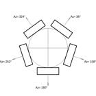
Fig. 3. Top view of the FM antenna system
The antenna is operating in horizontal polarization. Fig. 4 presents the VRP of the antenna on each of 7 operating frequencies (88.2 MHz, 92.3 MHz, 96.2 MHz, 101.4 MHz, 105.3 MHz, 106.5 MHz and 107.2 MHz) at the azimuths of the antenna faces (36°, 108°, 180°, 252° and 324°).

Fig. 4. The VRP’s of the FM antenna for 7 operating frequencies, before the modification
Taking into account the FM antenna height (99 m agl) the distances 30–75 m to the antenna tower (the region with too high radiation levels) correspond to elevation angles 12°–163° (the elevation angle 90° is parallel to the ground). Thus, in this range the VRP level should be minimized.
It can be seen that for the elevation angles 142°–163° the VRP levels are relatively high, especially for the highest operating frequencies. The detailed analysis revealed that the three of these frequencies: 107.2 MHz, 105.3 MHz and 101.4 MHz, were the main contributors to the combined electric field strength.
Modification of the VRP of the FM antenna system
There are no strict methods of the synthesis/modification of the VRP of an antenna system. So the only way is a trial-and-error method based on many simulations in which certain changes of the antenna system configuration have to be checked. In our case the aim is to minimize the sidelobes of the VRP in the range of angles 142° - 163° in such a way that the other sidelobes do not increase significantly.
The task is not easy because this is a known fact that, generally, when the radiation level is reduced in some direction then there are other directions where the radiation levels must increase (the total emitted power is constant). The goal is to achieve a compliance with regulations in the whole area accessible to people, therefore, the modifications of the FM antenna system should be made very carefully. The thorough consideration of many possible modifications allows to find configuration that meets the requirements. Three main conditions have to be always taken into account in the procedure:
-
other sidelobes of the VRP should be under control otherwise in other areas the exposure limits may be exceeded
-
the VRP from the service point of view (main beam tilt and null filling) should be preserved
-
the proposed changes should be as minimal as possible for economic reasons
For the modification of the VRP of the antenna system an efficient computational tool is needed, which would allow someone who does the job to follow the changes in the field distribution instantaneously after a trial modification to the system is introduced. Such an opportunity is offered by the simplified synthetic model in which the far field (for the whole system) and the scalar wave approximations are applied. The model has been implemented in the computer code ANTCHAR, developed in Orange Labs Poland. It should be mentioned that in the trial-and-error method the human factor (knowledge, experience, proficiency, efficiency) is very important.
Reconfiguration of the high-power FM antenna system
Finally, a new configuration of the FM antenna system has been found that meets the requirements. Many changes in the antenna system were necessary because of a very big level of required reduction of the radiation level (from about 12 V/m to 7 V/m). The changes were as follows:
-
5 (of the total 10) bays have been shifted vertically to achieve lower distance between bays
-
the step above resulted in additional space and one additional bay have been added (final configuration is 11 bays and 5 faces),
-
the relative phases on 5 bays have been changed (some cables were elongated), and
-
5 bays have been moved forward in horizontal plane from the antenna axis.
Fig. 5 shows the VRP’s for all the operating FM frequencies after the modifications had been introduced. A comparison between Figs. 4 and 5 shows that VRP’s has changed on each operating frequency and in all cases this changes are similar and lead to reduction of the radiation in the desired range of elevation angles (142°-163°).
In the given example the proposed changes were extended, but the aim has been achieved: a substantial decrease in the VRP level in the appropriate interval of elevation angles. The field reduction has been biggest for the three highest operating frequencies, and for the remaining ones it has been smaller. The time needed to find the proper system reconfiguration was about 4 hours.

Fig. 5. The VRP’s of the FM antenna for 7 operating frequencies, after the modification
The modification of the VRP did not affect significantly the coverage characteristics of the antenna system:
-
the antenna directivity has slightly changed (from -0.4 dB for the lowest frequency up to +0.4 to the highest frequency),
-
the main beam tilt (90.7°) is higher by 0.5° – this is fully acceptable because the elevation to the radio horizon depends on the azimuth and is varying from 90.4° to 90.7°, thus the previous beam tilt (90.2°) was too low,
-
the first null filling is lower but still acceptable,
-
the second null filling is lower but still acceptable.
Thus, the parameters important for the operational performance of the antenna system (directivity, nulls fill, beam tilt) have been preserved.
The combined electric field strength after modification of the VRP of the FM antenna
In the final step the EMF distribution in the area around the transmitting station has been evaluated using the full synthetic model, in order to confirm that the proposed modification will make transmitting station compliant with regulations.
In Fig. 6 the results are presented which correspond to Fig. 2. No changes were introduced to the TV UHF antenna except one additional DVB-T emission in channel 58 (f = 770 MHz) have been added. All the radiocommunication emissions remained unchanged.

Fig. 6. The combined electric field strength obtained from Eq.1 (black line) and contributing field components (colored lines) for the FM high power antenna – azimuth 180° – after modification.
A comparison of Figs 2 and 6 shows a substantial reduction of the combined electric field strength. It can be seen in the above figures that the combined electric field strength is less than 7 V/m in all places accessible to people. This means that the proposed modifications make the transmitting station compliant with regulations concerning protection against non-ionizing radiation. The proposed changes have been introduced in the real system and the control measurement performed. The results of the calculations were confirmed by measurements: the highest level of the combined electric field strength of the value less than 7 V/m was reported. The transmitting station could operate with the assigned ERP (effective radiated power) and was compliant with regulations concerning the protection against non-ionizing radiation.
Conclusions.
The paper presents a method for modification of EM fields around transmitting stations, which uses the antenna numerical models of different level of approximation and accuracy. The 3-stage procedure joins high accuracy with high efficiency, the latter feature necessary in the main human-assisted trial-and-error stage. The task is done via the modification of the VRP of an antenna system.
The work has been stimulated by the necessity of reduction of field levels around transmitting stations, in regions where the levels exceed the safety limits for human exposure. The developed tools have been applied many times for that purpose and have proven to be effective. The modification is performed of the VRP of the antenna system carrying the emissions with highest contribution to the cumulative exposure (combined electric field strength). A real life example of application of the method is described and shows the effectiveness of the method.
References
-
1ICNIRP, Guidelines for limiting exposure to time-varying electric, magnetic and electromagnetic field (up to 300 GHz), 1998
-
2IEEE limits: IEEE Std C95.1 – 2005, IEEE Standard for Safety Levels with Respect to Human Exposure to Radio Frequency Electromagnetic Fields, 3 kHz to 300 GHz, October 2005.
-
3Polish regulations: Rozporzadzenie Ministra Srodowiska z dnia 30 pazdziernika 2003 r. w sprawie dopuszczalnych poziomow pol elektromagnetycznych w srodowisku oraz sposobow sprawdzania dotrzymania tych poziomow, Dz.U.2003.192.1883, Warsaw, 2003
-
4ITU-T Recommendation K.70: Mitigation techniques to limit human exposure to EMFs in the vicinity of radiocommunication stations, Geneva 2007.
-
5F. Lewicki,Importance of antenna VRP in radiation protection consideration, Proceedings of XVII International Wroclaw Symposium on EMC, pp. 123 – 126, Wroclaw, Poland 2004.
-
6J. C. Lin, Controversy over cellular mobile-telecommunication base-station-antenna installations, IEEE Antennas and Propagation Magazine, vol. 46, no.1, pp. 155-156, Feb. 2004
-
7J. C. Lin, A research program on the human impact of wireless telecommunications and other electromagnetic-field-emitting systems, IEEE Antennas and Propagation Magazine, vol. 46,no. 6. pp. 161-163, Dec. 2004
-
8J. C. Lin, Radio frequency exposure and safety associated with base stations used for personal wireless telecommunication, IEEE Antennas and Propagation Magazine, vol. 44, no. 1, pp. 180-183, Feb. 2002
-
9O. P. Ghandi, An on site dosimetry system for safety assessment of wireless base stations using spatial harmonic components, IEEE Trans. on Antennas and Propagation, vol. 51, no. 4, pp. 840-847, April 2003
-
10M. Kaluski, L. Stasierski, Electromagnetic field estimation in the vicinity of panel antenna system for FM and TV broadcasting, IEEE Trans. on Broadcasting, vol. 41, no 4, pp. 136-142, Dec. 1995
-
11B. Fourestié, J-C. Bolomey, T. Sarrebourse, Z Altman, J. Wiart, Spherical Near Field Facility for Characterizing Random Emissions, IEEE Trans. on Antennas and Propagation vol. 53, pp. 2582-2589, Aug. 2005
-
12M-Ch. Gosselin, A. Christ, S. K¨uhn, N. Kuster, Dependence of the Occupational Exposure to Mobile Phone Base Stations on the Properties of the Antenna and the Human Body, IEEE Trans. on Electromagnetic Compatibility, vol. 51, no. 2, pp. 227-235, May 2009
-
13B. Thors, M. L. Strydom, B. Hansson, F. J. C. Meyer, K. K¨arkk¨ainen, P. Zollman, S. Ilvonen, Ch. T¨ornevik, On the Estimation of SAR and Compliance DistanceRelated to RF Exposure From Mobile Communication Base Station Antennas, IEEE Trans. on Electromagnetic Compatibility, vol. 50, no. 4, pp. 837-848, Nov. 2008
-
14A. Faraone, R. Y.-S. Tay, K. H. Joyner, and Q. Balzano, “Estimation of the average power density in the vicinity of cellular base-station collinear array antennas,” IEEE Trans. Veh. Technol., vol. 49, no. 3, pp. 984–996, May 2000.
-
15Y. Adane, A. Gati, M.-F. Wong, C. Dale, J. Wiart, and V. F. Hanna, “Optimal modeling of real radio base station antennas for human exposure assessment using spherical-mode decomposition,” IEEE Antennas Wireless Propag. Lett., vol. 1, pp. 215–218, 2002.
-
16R. Cicchetti and A. Faraone, “Estimation of the peak power density in the vicinity of cellular and radio base station antennas,” IEEE Trans. Electromagn. Compat., vol. 46, no. 2, pp. 275–290, May 2004.
-
17J. Cooper, B. Marx, J. Buhl, and V. Hombach, “Determination of safety distance limits for a human near a cellular base station antenna, adopting the IEEE Standard or ICNIRP Guidelines,” Bioelectromagnetics, vol. 23, no. 6, pp. 429–443, 2002.
-
18P. Bernardi, M. Cavagnaro, R. Cicchetti, S. Pisa, E. Piuzzi, and O. Testa, “A UTD/FDTD investigation on procedures to assess compliance of cellular base-station antennas with human-exposure limits in a realistic urban environment,” IEEE Trans. Microw. Theory Tech., vol. 51, no. 12, pp. 2409–2417, Dec. 2003.
-
19W. Joseph and L. Martens, “Comparison of safety distances based on the electromagnetic field and based on the sar for occupational exposure of a 900 MHz base station antenna,” IEEE Trans. Electromagn. Compat., vol. 47, no. 4, pp. 977–985, Nov. 2005.
-
20F. J. C. Meyer, D. B. Davidson, U. Jakobus, and M. A. Stuchly, “Human exposure assessment in the near field of GSM base-station antennas using a hybrid finite element/method of moments technique,” IEEE Trans. Biomed. Eng., vol. 50, no. 2, pp. 224–233, Feb. 2003
-
21L. Catarinucci, P. Palazzari, and L. Tarricone, “Human exposure to the near field of radiobase antennas—a full wave solution using parallel FDTD,” IEEE Trans.Microw. Theory Tech., vol. 51, no. 3, pp. 935–940, Mar. 2003.
-
22M. J. van Wyk, M. Bingle, and F. J. C. Meyer, “Antenna modeling considerations for accurate SAR calculations in human phantoms in close proximity to GSM cellular base station antennas,” Bioelectromagnetics, vol. 26, pp. 502–509, 2005.
-
23EN 50383, Basic standard for the calculation and measurement of electromagnetic field strength and SAR related to human exposure from radio base stations and fixed terminal stations for wireless telecommunication systems, CENELEC, Brussels, August 2002.
Publication Dates
-
Publication in this collection
June 2015
History
-
Received
12 Jan 2015 -
Reviewed
29 Jan 2015 -
Accepted
18 June 2015

 Thumbnail
 Thumbnail
 Thumbnail
 Thumbnail


