Abstract
This paper presents a patch antenna array topology for Simultaneous Wireless Information and Power Transfer (SWIPT) applications. The resulting Double Patch Antenna Array (DPA) is composed of two patch antennas operating at different frequencies and fabricated on a unique substrate. One of the patches operates at the 1.8 GHz mobile communication band and is used for wireless communication, while the other one operates at the 2.4 GHz Industrial, Scientific, and Medical (ISM) band, and is used for Radio Frequency Energy Harvesting (RFEH). The analyzes and measurements carried out have shown that the adopted topology has satisfactory performance for communication, with a gain of 1.5 dBi, and for out-of-band energy harvesting, with a Vout of 160 mV at 2.45 GHz. These results indicate this approach as a promising strategy for low-power wireless applications.
Index Terms
Patch Antenna Array; Rectenna; RF Energy Harvesting; Wireless Communication; SWIPT
I. INTRODUCTION
Currently, wireless communication is a global trend and its use has connected a large number of devices, which are expected to surpass hundreds of billions soon [1[1] J. G. Andrews, S. Buzzi, W. Choi, S. V. Hanly, A. Lozano, A. C. K. Soong and J. C. Zhang, “What Will 5G Be?,” IEEE Journal on Selected Areas in Communications, vol. 32, pp. 1065-1082, 6 2014.], [2[2] A. Osseiran, F. Boccardi, V. Braun, K. Kusume, P. Marsch, M. Maternia, O. Queseth, M. Schellmann, H. Schotten, H. Taoka, H. Tullberg, M. A. Uusitalo, B. Timus and M. Fallgren, “Scenarios for 5G mobile and wireless communications: the vision of the METIS project,” IEEE Communications Magazine, vol. 52, pp. 26-35, 5 2014.]. These devices, with different purposes and requirements, present challenges not only in their communication performance improvement, but also in their energy supply [3[3] H. Bello, Z. Xiaoping, R. Nordin and J. Xin, “Advances and Opportunities in Passive Wake-Up Radios with Wireless Energy Harvesting for the Internet of Things Applications,” Sensors, vol. 19, p. 3078, 7 2019.]. Many energy harvesting techniques have been considered to overcome this energy challenge and to turn these devices totally or partially independent of wires and batteries.
Energy harvesting is the process of taking energy from different sources (e.g., Radio Frequency (RF), thermal, solar, mechanical) and to convert it into electrical energy for supply electric/electronic devices [4[4] E. H. Callaway, Wireless sensor networks, Boca, Raton: Auerbach Publications, 2004.]. Among these sources, Radio Frequency Energy Harvesting (RFEH) appears as a good candidate to supply energy to wireless devices due to its versatility and power sources with, usually, constant and controllable energy transfer [5[5] X. Lu, P. Wang, D. Niyato, D. I. Kim and Z. Han, “Wireless Networks With RF Energy Harvesting: A Contemporary Survey,” IEEE Communications Surveys & Tutorials, vol. 17, pp. 757-789, 2015.], [6[6] Y. S. Gonçalves, U. C. Resende and Í. V. Soares, “Electromagnetic Energy Harvesting Using a Glass Window,” Journal of Microwaves, Optoelectronics and Electromagnetic Applications, vol. 19, pp. 50-59, 3 2020.]. These characteristics enable RFEH with a dedicated energy source, also defined as Wireless Power Transfer (WPT), a promising strategy for supplying power to communication systems with consumption in the order of μW.
In order to reach the expected self-powered wireless devices, one of the most interesting alternatives is the combination of Wireless Information Transfer (WIT) and WPT technologies. Research on the Simultaneous Wireless Information and Power Transfer (SWIPT), started in [7[7] P. Grover and A. Sahai, “Shannon meets Tesla: Wireless information and power transfer,” in 2010 IEEE International Symposium on Information Theory, 2010.], taking into account all the challenges and strategies involved, has become the focus of several technical publications in recent years. [5[5] X. Lu, P. Wang, D. Niyato, D. I. Kim and Z. Han, “Wireless Networks With RF Energy Harvesting: A Contemporary Survey,” IEEE Communications Surveys & Tutorials, vol. 17, pp. 757-789, 2015.], [8[8] T. D. P. Perera, D. N. K. Jayakody, S. K. Sharma, S. Chatzinotas and J. Li, “Simulataneous Wireless Information and Power Transfer (SWIPT): Recent Advances and Future Challenges.,” IEEE Communications Surveys & Tutorials, vol. 20, 2018.], [9[9] D. N. K. Jayakody, J. Thompson, S. Chatzinotas and S. Durrani, Eds., Wireless Information and Power Transfer: A New Paradigm for Green Communications, Springer International Publishing, 2018.]. However, it can be noted that there is still a great lack of new microwave designs in this area, which can be proposed and explored by researchers and technological industries.
Among the strategies for using RFEH in the energy supply of wireless devices, the out-of-band approach has stood out, as shown in Fig. 1. The advantages of this SWIPT approach are to avoid self-interference of dedicated sources and competition for the same RF carrier, reusing RF energy from different RF sources on the environment [10[10] S. Bi, Y. Zeng and R. Zhang, “Wireless powered communication networks: an overview,” IEEE Wireless Communications, vol. 23, pp. 10-18, 4 2016.].

To use this strategy, the rectenna, which is the connection of an antenna and a RF rectifier, can use several antenna designs, and among them, the microstrip patch antenna has been widely used due to its good constructive characteristics (simplicity, small dimensions, and easy fabrication) and performance (resonance frequency, polarization, and radiation pattern) [11[11] S. Shrestha, S.-K. Noh and D.-Y. Choi, “Comparative Study of Antenna Designs for RF Energy Harvesting,” International Journal of Antennas and Propagation, vol. 2013, pp. 1-10, 2013.].
In this context, it is proposed a Double Patch Antenna Array (DPA) fabricated on a unique substrate, operating at different frequencies, with a minimum attenuation or coupling between them.
The operating bands for WIT and WPT, in this proposal, are the 1.8 GHz mobile communication band and 2.4 GHz Industrial, Scientific, and Medical (ISM) band, respectively. The adoption of this WPT band was based on the average power density available at urban indoor environments [12[12] K. Huang and X. Zhou, “Cutting the last wires for mobile communications by microwave power transfer,” IEEE Communications Magazine, vol. 53, pp. 86-93, 6 2015.].
In addition, for this fully WPT implementation, an RF rectifier, also designed and fabricated, is connected at the 2.45 GHz patch antenna port, constituting a rectenna element. Both DPA and the RF rectifier was designed using an FR4 substrate (εr = 4.5, tanδ = 0.018, and h = 1.6 mm) with metallization on both sides. It was chosen due to its low cost, easy acquisition, and satisfactory characteristics at the desired frequency range [13[13] C. E. Capovilla, A. A. S. Tavora and L. C. Kretly, “A fully integrated CMOS low noise amplifier with multiple switched inputs for diversity wireless communications,” IEEE International Microwave and Optoelectronics Conference, 10 2007.], [14[14] E. V. V. Cambero, H. P. Paz, V. S. Silva, H. X. Araujo, I. R. S. Casella and C. E. Capovilla, “A 2.4 GHz Rectenna based on a Solar Cell Antenna Array,” IEEE Antennas and Wireless Propagation Letters, p. 1–1, 2019.].
The paper is organized as follows: besides this introduction, the DPA design and the antenna characterization are shown in section II, the RF rectifier design, the main analysis, and results of the DPA as a rectenna are considered in section III, and finally, section IV concludes this work.
II. DPA Design
A. Antenna design
After a classical hand-calculation for patch antennas, which can be verified in [15[15] C. A. Balanis, Antenna Theory: Analysis and Design, 3 ed., Wiley-Interscience, 2005.], simulations were performed using the Keysight Advanced Design System (ADS) to optimize the performance of the DPA. The microstrip feed line, for both patches, was made as a cutout in a radiating edge, which is inset to a 50 Ω driving point [16[16] R. Bancroft, Microstrip and Printed Antenna Design, Second ed., Scitech, 2009.], [17[17] D. Fonseca, F. Pereira and U. R. C. Vitor, “Study of Patch Antennas with Koch Curve Form Slots,” Journal of Microwaves, Optoelectronics and Electromagnetic Applications, vol. 18, pp. 399-407, 7 2019.].
In this way, Fig. 2 shows the DPA layout with the designed patches having the following optimized dimensions (in mm): Wf = 2.80, W1 = 34.00, W2 = 26.00, Lf1 = 31.00, Lf2 = 25.00, Lif1 = 13.00, Lif2 = 10.00, L1 = 40.00, L2 = 29.50, Sif = 1.35 and Sant = 10.00.

Due to the narrowband nature of the patch antennas and the relatively far apart operating frequencies (when compared with their respective bandwidth), the separation between antennas (Sant) is not a critical design parameter. The exaggerated undersizing of Sant would generate a partial degradation of the radiation pattern in the direction of the complementary antenna, acting as a reflective element, but not affecting the performance of the direct link. On the other hand, the oversizing causes an unnecessary increase in the prototype dimensions. Despite this fact, none of these design issues affect the input return loss or the mutual coupling between the antennas.
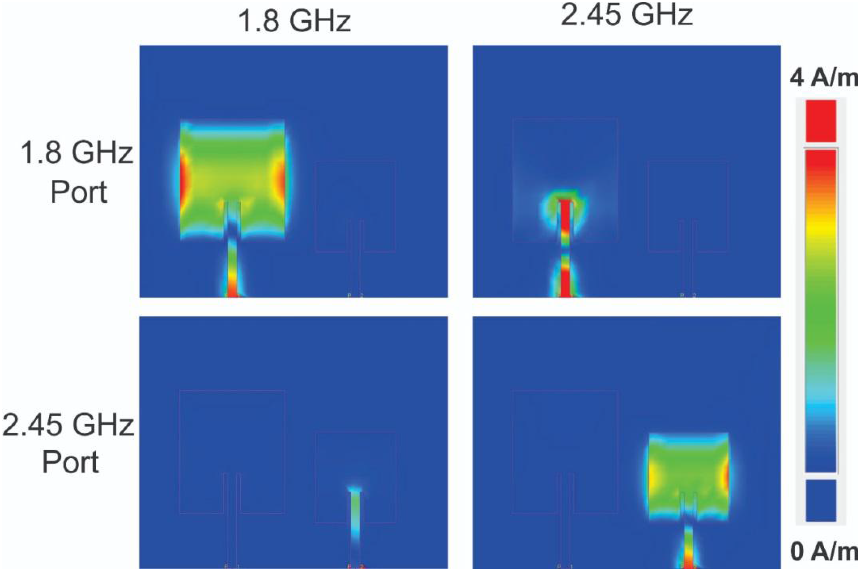
A current density simulation was also performed in ADS to analyze the coupling between the elements of the DPA. An RF source with a frequency equal to the central frequency of each operating band was applied in each port of the DPA, while the other port was matched with a 50 Ω load.
In Fig. 3 is shown a very low coupling between the antennas (only the excited antenna is “shining”) and satisfactory performance at their respective designed frequency, in opposition to their poor performance at the complementary one. Since the simulation results are in agreement with the primary specifications, the DPA prototype, presented in Fig. 4, was fabricated on the low-cost FR4 substrate.

Current density of DPA for RF sources applied to the port of 1.8 (top) and 2.45 GHz (bottom) at the frequencies of 1.8 (left) and 2.45 GHz (right).

B. Antenna characterization
In order to confirm the simulation results and to determine the operating frequency of the prototype, the reflection coefficient (S11) measurement of the DPA was done with the Rohde & Schwarz ZVB8 Vector Network Analyzer, with the complementary port connected to a 50 Ω load. The simulation and measurement results for DPA S11 are shown in Fig. 5.

Fig. 5 shows that the experimental results are in good agreement with those of the simulation, overlapping the deep points (according to the designed frequencies) and presenting the same bandwidth, attesting the validity of the substrate parameters used by the Method of Moments (MoM uW) in the ADS simulation.
The radiation pattern characteristics of the DPA, at both frequencies, 1.8 and 2.45 GHz, were measured inside an anechoic chamber, based on the ETS-Lindgren Spacesaver H26 Model, in the Laboratory of Information and Communication (LIC) at the Federal University of ABC (UFABC). The Fig. 6 shows the simulated and measured radiation pattern characteristics for each corresponding patch antenna, with the other one matched using a 50 Ω load, at 1.8 (a) and 2.45 GHz (b), respectively.

Analyzing the measured H-field of the radiation pattern presented in Fig. 6 (the imaginary plane, orthogonal to the substrate and that cuts both radiant elements simultaneously), it is observed that there is asymmetry (around 3 dB) between the upper and lower bounds (90° and 270°, respectively) in both frequencies and that this power difference occurs in the opposite side for each antenna. This configuration suggests that there is an interaction between the active elements with respect to their radiation characteristics.
The explanation for this problem was mentioned when discussing the effect of undersizing the parameter Sant (section II.A). This fact is just a statement of the evidence presented, and does not critically interfere with the performance of the DPA. Finally, the DPA measured gains are 1.5 and 1.8 dBi, at 1.8 and 2.45 GHz, respectively. These results are in agreement with the typical gain of this antenna architecture [16[16] R. Bancroft, Microstrip and Printed Antenna Design, Second ed., Scitech, 2009.].
III. Experimental Rectenna Characterization
A. RF rectifier design and characterization
A series half-wave rectifier is designed with a matching microstrip line, as shown in Fig. 7. This topology was chosen due to its simplicity and operational characteristics in the desired band [18[18] T. Soyata, L. Copeland and W. Heinzelman, “RF Energy Harvesting for Embedded Systems: A Survey of Tradeoffs and Methodology,” IEEE Circuits and Systems Magazine, vol. 16, pp. 22-57, 2016.], [19[19] L.-G. Tran, H.-K. Cha and W.-T. Park, “RF power harvesting: a review on designing methodologies and applications,” Micro and Nano Systems Letters, vol. 5, 2 2017.]. The Schottky diode (D) SMS7630-079LF by Skyworks is used due to its low zero-bias junction resistance and capacitance, inversely related to the diode's efficiency [20[20] R. L. R. Silva, S. T. M. Gonçalves, C. Vollaire, A. Bréard, G. L. Ramos and C. G. Rego, “Analysis and Optimization of Ultra-Low-Power Rectifier with High Efficiency for Applications in Wireless Power Transmission and Energy Harvesting,” Journal of Microwaves, Optoelectronics and Electromagnetic Applications, vol. 19, pp. 60-85, 3 2020.]. The output capacitance C (100 pF) and the output inductance L (10 μH) compose the output Low-Pass Filter (LPF), which is responsible for the output voltage (Vout) suppression [21[21] H. P. Paz, “Estudo e implementação de retificadores de radiofrequência para rectenas”, M.S. thesis, UFABC, Santo André, SP, Brazil, 2020.].

The output load (RL), which maximizes the RF rectifier efficiency, determined by the ADS Large - Signal S-Parameters (LSSP) simulation, is equal to 1.5 kΩ. Both RL and LPF elements (L and C) are general purpose Surface Mounted Device (SMD) components usually used in RF front-end circuits.
Along with the RF rectifier circuit, the matching network (MN) represents an essential element for the maximum power transfer from the antenna to the series rectifier output. The proposed element, besides the microstrip line, is composed of an open stub, for impedance matching, and a grounded one, responsible for eliminating the direct current voltage (VDC) component at the diode anode, which can decrease the series rectifier efficiency significantly [22[22] H. P. Paz, V. S. Silva, E. V. V. Cambero, H. X. Araújo, I. R. S. Casella and C. E. Capovilla, “A survey on low power RF rectifiers efficiency for low cost energy harvesting applications,” AEU - International Journal of Electronics and Communications, vol. 112, p. 152963, 12 2019.], [23[23] T. Ngo and Y.-X. Guo, “Harmonic-Recycling Rectifier for High-Efficiency Far-Field Wireless Power Transfer,” IEEE Transactions on Circuits and Systems II: Express Briefs, vol. 67, p. 770–774, 4 2020.]. So, the RF rectifier layout with the optimized MN, presented in Fig. 7, has the following dimensions (in mm): Wm = Wos = 3.00, Wgs = 0.50, Lm = 30.30, Los = 13.00, Lgs = 19.00, and Dos = 15.00.
The S11 of the RF rectifier was used for matching the circuit at central frequency of the 2.4 GHz ISM band, through simulations, considering PIN variations from −30 to −10 dBm. According to this procedure, in Fig. 8, it can be observed that the measured S11 deeps of the prototype are at the desired frequency operation range.

The series rectifier efficiency versus the input power at the rectifier (PIN) at 2.45 GHz is presented in Fig. 9. The obtained efficiency values are satisfactory, for low power applications, reaching 10.5% for −20 dBm and 26% for −10 dBm.

B. Rectenna measurements
With the proposal of estimate the rectenna parameters, a quasi-Yagi antenna [24[24] C. E. Capovilla, “Antenas planares aplicadas às Comunicações Móveis de últimas gerações utilizando elementos Quasi-Yagi,” M.S. thesis, FEEC/UNICAMP, Campinas, SP, Brazil, 2004.] [25[25] L. C. Kretly and C. E. Capovilla, “A Novel Antenna Array Based on Quasi-Yagi Element for Adaptive Wireless System Applications,” IEEE International Microwave and Optoelectronics Conference, vol. 01, pp. 307-312, 9 2003.] was used to transmitting a Continuous Wave (CW) RF signal with linear polarization, being used in a link implemented inside an anechoic chamber, as shown in Fig. 10. The gain of 3.8 dBi of the quasi-Yagi antenna and its maximum dimension of 11 cm, combined with the equipment power limitation (RF generator Keysight N9320A), it is sufficient to ensure that PIN can vary from −20 to −10 dBm, or, in this case, that the average power density (SAV) can vary from 0.5 to 5 μW/cm2, in the far-field region at 2.45 GHz (WPT frequency only), for a link distance of 40 cm.

From the metrics commonly associated with RFEH [18[18] T. Soyata, L. Copeland and W. Heinzelman, “RF Energy Harvesting for Embedded Systems: A Survey of Tradeoffs and Methodology,” IEEE Circuits and Systems Magazine, vol. 16, pp. 22-57, 2016.], [19[19] L.-G. Tran, H.-K. Cha and W.-T. Park, “RF power harvesting: a review on designing methodologies and applications,” Micro and Nano Systems Letters, vol. 5, 2 2017.], it has chosen for this work: Vout, due to be the only directly measurable parameter; the output power (Pout), due to be a parameter independent of the RF rectifier load; and, finally, the conversion efficiency (ηRF-DC).
The independent variables must be associated with the RF generator output power at 2.45 GHz (at the transmitting antenna terminal) since this is the only independent variable. In this way, through the Friis equation [26[26] D. M. Pozar, Microwave Engineering, 4 ed., John Wiley & Sons, 2012.], the SAV in the DPA region and PIN (power at the interface DPA-rectifier) can be defined. So, ηRF-DC is given by:
In order to better understand the metrics used, it is assumed that ηRF-DC is related to the independent variable PIN (which appears in its equation), while the other parameters are related to SAV. This one is a more coherent independent variable in the analysis of rectenna, that is, in fact, a device that converts SAV to DC power. In this way, these analyses can also be intrinsically associated with the efficiency of the antenna.
The Fig. 11(a) shows the ηRF-DC performance of the DPA with a maximum value of 19% for PIN = −11 dBm, that matches to Vout = 160 mV and Pout = 17μW at SAV = 5 μW/cm2 (Fig. 11(b)), which are satisfactory results for a SWIPT system with out-of-band RFEH, using antennas in a unique substrate. However, the narrow bandwidth of the DPA represents an impedance variation around the optimum point, which, in addition to the nonlinear behavior and narrow bandwidth of the RF rectifier, can turn the system performance susceptible to the available power in the environment.

IV. CONCLUSIONS
In this paper, a planar antenna array configuration is proposed, based on a patch antenna topology, presenting two outputs for simultaneous telecommunication and energy harvesting applications. Two patch antennas, for 1.8 and 2.45 GHz, were fabricated on the same substrate in order to optimize the prototype dimensions without decreasing the performance in communication or RFEH. The gain of 1.5 dBi at 1.8 GHz and Vout of 160 mV at 2.45 GHz energy harvesting, makes this proposal a promising step in the direction of a SWIPT system with out-of-band RFEH for low-power wireless applications.
ACKNOWLEDGMENT
This research was partially supported by CNPq (309848/2018-0), CAPES (Finance Code 001), and FAPESP (2019/25866-7).
REFERENCES
-
[1]J. G. Andrews, S. Buzzi, W. Choi, S. V. Hanly, A. Lozano, A. C. K. Soong and J. C. Zhang, “What Will 5G Be?,” IEEE Journal on Selected Areas in Communications, vol. 32, pp. 1065-1082, 6 2014.
-
[2]A. Osseiran, F. Boccardi, V. Braun, K. Kusume, P. Marsch, M. Maternia, O. Queseth, M. Schellmann, H. Schotten, H. Taoka, H. Tullberg, M. A. Uusitalo, B. Timus and M. Fallgren, “Scenarios for 5G mobile and wireless communications: the vision of the METIS project,” IEEE Communications Magazine, vol. 52, pp. 26-35, 5 2014.
-
[3]H. Bello, Z. Xiaoping, R. Nordin and J. Xin, “Advances and Opportunities in Passive Wake-Up Radios with Wireless Energy Harvesting for the Internet of Things Applications,” Sensors, vol. 19, p. 3078, 7 2019.
-
[4]E. H. Callaway, Wireless sensor networks, Boca, Raton: Auerbach Publications, 2004.
-
[5]X. Lu, P. Wang, D. Niyato, D. I. Kim and Z. Han, “Wireless Networks With RF Energy Harvesting: A Contemporary Survey,” IEEE Communications Surveys & Tutorials, vol. 17, pp. 757-789, 2015.
-
[6]Y. S. Gonçalves, U. C. Resende and Í. V. Soares, “Electromagnetic Energy Harvesting Using a Glass Window,” Journal of Microwaves, Optoelectronics and Electromagnetic Applications, vol. 19, pp. 50-59, 3 2020.
-
[7]P. Grover and A. Sahai, “Shannon meets Tesla: Wireless information and power transfer,” in 2010 IEEE International Symposium on Information Theory, 2010.
-
[8]T. D. P. Perera, D. N. K. Jayakody, S. K. Sharma, S. Chatzinotas and J. Li, “Simulataneous Wireless Information and Power Transfer (SWIPT): Recent Advances and Future Challenges.,” IEEE Communications Surveys & Tutorials, vol. 20, 2018.
-
[9]D. N. K. Jayakody, J. Thompson, S. Chatzinotas and S. Durrani, Eds., Wireless Information and Power Transfer: A New Paradigm for Green Communications, Springer International Publishing, 2018.
-
[10]S. Bi, Y. Zeng and R. Zhang, “Wireless powered communication networks: an overview,” IEEE Wireless Communications, vol. 23, pp. 10-18, 4 2016.
-
[11]S. Shrestha, S.-K. Noh and D.-Y. Choi, “Comparative Study of Antenna Designs for RF Energy Harvesting,” International Journal of Antennas and Propagation, vol. 2013, pp. 1-10, 2013.
-
[12]K. Huang and X. Zhou, “Cutting the last wires for mobile communications by microwave power transfer,” IEEE Communications Magazine, vol. 53, pp. 86-93, 6 2015.
-
[13]C. E. Capovilla, A. A. S. Tavora and L. C. Kretly, “A fully integrated CMOS low noise amplifier with multiple switched inputs for diversity wireless communications,” IEEE International Microwave and Optoelectronics Conference, 10 2007.
-
[14]E. V. V. Cambero, H. P. Paz, V. S. Silva, H. X. Araujo, I. R. S. Casella and C. E. Capovilla, “A 2.4 GHz Rectenna based on a Solar Cell Antenna Array,” IEEE Antennas and Wireless Propagation Letters, p. 1–1, 2019.
-
[15]C. A. Balanis, Antenna Theory: Analysis and Design, 3 ed., Wiley-Interscience, 2005.
-
[16]R. Bancroft, Microstrip and Printed Antenna Design, Second ed., Scitech, 2009.
-
[17]D. Fonseca, F. Pereira and U. R. C. Vitor, “Study of Patch Antennas with Koch Curve Form Slots,” Journal of Microwaves, Optoelectronics and Electromagnetic Applications, vol. 18, pp. 399-407, 7 2019.
-
[18]T. Soyata, L. Copeland and W. Heinzelman, “RF Energy Harvesting for Embedded Systems: A Survey of Tradeoffs and Methodology,” IEEE Circuits and Systems Magazine, vol. 16, pp. 22-57, 2016.
-
[19]L.-G. Tran, H.-K. Cha and W.-T. Park, “RF power harvesting: a review on designing methodologies and applications,” Micro and Nano Systems Letters, vol. 5, 2 2017.
-
[20]R. L. R. Silva, S. T. M. Gonçalves, C. Vollaire, A. Bréard, G. L. Ramos and C. G. Rego, “Analysis and Optimization of Ultra-Low-Power Rectifier with High Efficiency for Applications in Wireless Power Transmission and Energy Harvesting,” Journal of Microwaves, Optoelectronics and Electromagnetic Applications, vol. 19, pp. 60-85, 3 2020.
-
[21]H. P. Paz, “Estudo e implementação de retificadores de radiofrequência para rectenas”, M.S. thesis, UFABC, Santo André, SP, Brazil, 2020.
-
[22]H. P. Paz, V. S. Silva, E. V. V. Cambero, H. X. Araújo, I. R. S. Casella and C. E. Capovilla, “A survey on low power RF rectifiers efficiency for low cost energy harvesting applications,” AEU - International Journal of Electronics and Communications, vol. 112, p. 152963, 12 2019.
-
[23]T. Ngo and Y.-X. Guo, “Harmonic-Recycling Rectifier for High-Efficiency Far-Field Wireless Power Transfer,” IEEE Transactions on Circuits and Systems II: Express Briefs, vol. 67, p. 770–774, 4 2020.
-
[24]C. E. Capovilla, “Antenas planares aplicadas às Comunicações Móveis de últimas gerações utilizando elementos Quasi-Yagi,” M.S. thesis, FEEC/UNICAMP, Campinas, SP, Brazil, 2004.
-
[25]L. C. Kretly and C. E. Capovilla, “A Novel Antenna Array Based on Quasi-Yagi Element for Adaptive Wireless System Applications,” IEEE International Microwave and Optoelectronics Conference, vol. 01, pp. 307-312, 9 2003.
-
[26]D. M. Pozar, Microwave Engineering, 4 ed., John Wiley & Sons, 2012.
Publication Dates
-
Publication in this collection
16 Sept 2020 -
Date of issue
Sept 2020
History
-
Received
20 Apr 2020 -
Reviewed
23 Apr 2020 -
Accepted
16 July 2020