Abstract
The goal of this article is to present the formulation of the optimization problem of truss structures with geometric nonlinearity under dynamic loads and provide examples of this problem. The formulated optimization problem aims to determine the cross-sectional area of the bars that minimizes the weight of the structure, imposing constraints on nodal displacements and axial stresses. To solve this problem, computational routines were developed in MATLAB® using Sequential Quadratic Programming (SQP), the algorithm of which is available on MATLAB’s Optimization ToolboxTM. The nonlinear finite space truss element is described by an updated Lagrangian formulation. The geometric nonlinear dynamic analysis performed combines the Newmark method with Newton-Raphson iterations. It was validated by a comparison with solutions available in literature and with solutions generated by the ANSYS® software. Optimization examples of trusses under different dynamic loading were studied considering their geometric nonlinearity. The results indicate a significant reduction in structure weight for both undamped and damped cases.
Keywords:
structural optimization; geometric nonlinearity; dynamic analysis; damping ratio; trusses
Keywords:
structural optimization; geometric nonlinearity; dynamic analysis; damping ratio; trusses
1. Introduction
The importance of considering dynamic effects and nonlinear behavior when studying truss structures has been well established in the past decades. The consideration of dynamic effects is of great relevance for designing structures subjected to earthquakes or structures subjected to random vibrations, as presented by Alves and Vaz (2013)ALVES, E. C.; VAZ, L. E. Optimum design of plates structures under random loadings. REM - Revista Escola de Minas , v. 66, n. 1, p. 41-47, 2013. and Alves (2016)ALVES, E. C. Optimization of structures subject to dynamic load: deterministic and probabilistic methods. REM - Revista Escola de Minas, v. 69, n. 3, p. 281-286, 2016.. On the other hand, studies on geometrical nonlinear structures, such as Crisfield (1991)CRISFIELD, M. A. Non-linear finite element analysis of solids and structures. Chichester: John Wiley & Sons, 1991. v. 1. , show that neglecting the deformations caused by this nonlinear behavior may lead to undersized structures with regard to the serviceability limit state.
The existing structural analysis literature includes many researches on the development and improvement of practical and efficient methodologies for nonlinear dynamic analysis of truss structures. Noor and Peters (1980)NOOR, A. K.; PETERS, J. M. Nonlinear dynamic analysis of space trusses. Computer Methods in Applied Mechanics and Engineering, v. 21, n. 2, p. 131-151, 1980. presented a computational procedure for predicting the dynamic response of space trusses with both geometric and material nonlinearities. It used a mixed formulation, with the fundamental unknowns consisting of member forces, nodal velocities and nodal displacements. The temporal integration of the governing equations was performed by using an explicit method. Kassimali and Bidhendi (1988)KASSIMALI, A.; BIDHENDI, E. Stability of trusses under dynamic loads. Computers & Structures, v. 29, n. 3, p. 381-392, 1988. studied the stability behavior and the large deformation response of trusses under dynamic loads. The analysis technique used an Eulerian formulation and the Newmark method. Zhu et al. (1994)ZHU, K.; AL-BERMANI, F. G. A.; KITIPORNCHAI, S. Nonlinear dynamic analysis of lattice structures. Computers & Structures, v. 52, n. 1, p. 9-15, 1994. presented a computational procedure for predicting the geometric and material nonlinear dynamic response of space trusses. It employed an updated Lagrangian formulation and the Newmark method. Wang et al. (2006)WANG, C.-Y.; WANG, R.-Z.; CHUANG, C.-C.; WU, T.-Y. Nonlinear dynamic analysis of reticulated space truss structures. Journal of Mechanics, v. 22, n. 3, p. 199-212, 2006. developed a formulation, named the vector form intrinsic finite element (VFIFE or V-5), for predicting the nonlinear dynamic behavior of space trusses. It was combined with an explicit time integration method and applied to several numerical examples. More recently, Shi et al. (2015)SHI, H.; SALIM, H.; SHI, Y.; WEI, F. Geometric and material nonlinear static and dynamic analysis of space truss structures. Mechanics Based Design of Structures and Machines, v. 43, p. 38-56, 2015. derived a formulation of a fully nonlinear truss element considering both geometric and material nonlinearities. The authors presented examples of space trusses subjected to static and dynamic loads in order to illustrate its application.
Survey on the structural optimization literature reveals that numerous researches have been conducted on truss structures considering only dynamic effects or only nonlinear behavior.
For instance, many researchers have been performing studies on the size optimization of nonlinear structures subjected to static loads. Pyrz (1990)PYRZ, M. Discrete optimization of geometrically nonlinear truss structures under stability constraints. Structural Optimization , v. 2, n. 2, p. 125-131, 1990. dealt with discrete optimization of elastic trusses with geometrical nonlinear behavior. The problem consisted of minimizing the weight of the structure considering constraints on element stresses, element stability and global structural stability. Saka and Ulker (1992)SAKA, M. P.; ULKER, M. Optimum design of geometrically nonlinear space trusses. Computers & Structures , v. 42, n. 3, p. 289-299, 1992. presented a structural optimization algorithm for geometrically nonlinear space trusses subject to displacement, stress and cross-sectional area constraints. It was shown that the consideration of nonlinear behavior in the optimum design makes it possible to achieve further reduction in the overall weight. Suleman and Sedaghati (2005)SULEMAN, A.; SEDAGHATI, R. Benchmark case studies in optimization of geometrically nonlinear structures. Structural and Multidisciplinary Optimization , v. 30, n. 4, p. 273-296, 2005. developed a structural optimization algorithm for truss and beam structures undergoing large deflections against instability. The authors presented several benchmark case studies and compared the results with solutions reported in literature. Hrinda and Nguyen (2008)HRINDA, G. A.; NGUYEN, D. T. Optimization of stability-constrained geometrically nonlinear shallow trusses using an arc length sparse method with a strain energy density approach. Finite Elements in Analysis and Design, v. 44, n. 15, p. 933-950, 2008. proposed a technique for the optimization of geometrically nonlinear shallow trusses with snap-through behavior subjected to stability constraints. It used the arc length method and a strain energy density approach within a discrete finite-element formulation.
Many others have been studying the size optimization of structures subjected to dynamic loading without considering nonlinear behavior. Ohno et al. (1989)OHNO, T.; KRAMER, G. J. E.; GRIERSON, D. E. Least-weight design of frameworks under multiple dynamic loads. Structural Optimization , v. 1, n. 3, p. 181-191, 1989. presented a computer-based structural design methodology for the minimum weight design of planar trusses subjected to multiple dynamic loads. It imposed constraints on nodal displacement, stresses and natural frequencies. Chen (1992)CHEN, T.-Y. Design optimization with static and dynamic displacement constraints. Structural Optimization, v. 4, n. 3-4, p. 179-185, 1992. proposed an optimization procedure using a sequential linear programming technique to design minimum weight structures subjected to static and dynamic displacement constraints. Kocer and Arora (2002)KOCER, F. Y.; ARORA, J. S. Optimal Design of Latticed Towers Subjected to Earthquake Loading. Journal of Structural Engineering, v. 128, n. 2, p. 197-204, 2002. formulated the problem of optimal design of latticed transmission towers subjected to an earthquake load. Azad et al. (2018)AZAD, S. K.; BYBORDIANI, M.; AZAD, S. K.; JAWAD, F. K. J. Simultaneous size and geometry optimization of steel trusses under dynamic excitations. Structural and Multidisciplinary Optimization, v. 58, p. 2545-2563, 2018. used the big bang-big crunch algorithm for addressing the simultaneous size and geometry optimization problem of steel trusses subjected to dynamic excitations.
However, it is rare to find articles on size optimization taking into account dynamic and nonlinear effects simultaneously, i.e. articles that study the size optimization of nonlinear structures under dynamic loads. Given the lack of data on this subject, this article aims to present the formulation of the optimization problem of truss structures with geometric nonlinearity under dynamic loads and provide examples of this problem.
2. Formulation of the geometrically nonlinear element
The finite element considered is illustrated in Figure 1a. It is a space truss element, limited by nodes A and B. Its nodal displacements and internal forces are also presented.
To describe the motion of this element, an updated Lagrangian formulation was adopted, which will be summarized below. For a detailed explanation, including deductions of the equations depicted here, see Yang and Kuo (1994)YANG, Y.-B.; KUO, S.-R. Theory and analysis of nonlinear framed structures. New York: Prentice Hall, 1994..
The current deformed configuration is called Cn, and the last known deformed configuration is referred to as Cn-1. As shown in Figure 1b, the element lengths under such configurations are Ln and Ln-1, respectively.
The nodal displacement generated during the incremental step from Cn-1 to Cn is given by:
where u, v and w are the nodal displacements in the x, y and z directions, respectively.
Correspondingly, the internal forces of the element under the last known deformed configuration fin-1 and the current deformed configuration fin are:
where fBxn-1 and fBxn are the internal forces of node B in the x direction, under configurations Cn-1 and Cn, respectively.
These vectors of internal forces interact with each other. This relation is described by the following equation:
where ∆fi is the incremental internal force vector, given by:
where E is the modulus of elasticity, A is the cross-sectional area, Ln-1 is the element length under configuration Cn-1 and Ln is the element length under configuration Cn.
The stiffness matrix (k) of the element is formed by five components: the elastic stiffness matrix (ke), the geometric stiffness matrix (kg) and the higher-order stiffness matrix (k1, k2 e k3 ). These matrices are given by:
k = k e + k g + k 1 + k 2 + k 3
where ∆u = uB- uA, ∆v = vB- vA and ∆w =wB-wA.
The stiffness matrix and the vector of internal forces of the element can be represented in the global system by the following equations:
where T is the transformation matrix.
Finally, the structure stiffness matrix (K) is obtained by combining the stiffness matrices of each element. Likewise, the vector of internal forces (Fi ) of the element is obtained by combining the internal force vectors of each element.
3. Geometrically nonlinear dynamic analysis
In the context of the finite element, the equation of motion of a structure can be written as:
where Ü, Ü and U are the vectors of nodal accelerations, velocities and displacements, respectively; M is the lumped mass matrix; C is the damping matrix; Fi is the vector of internal forces, which depends on nodal displacement vector U; and Fe is the time-dependent external load vector.
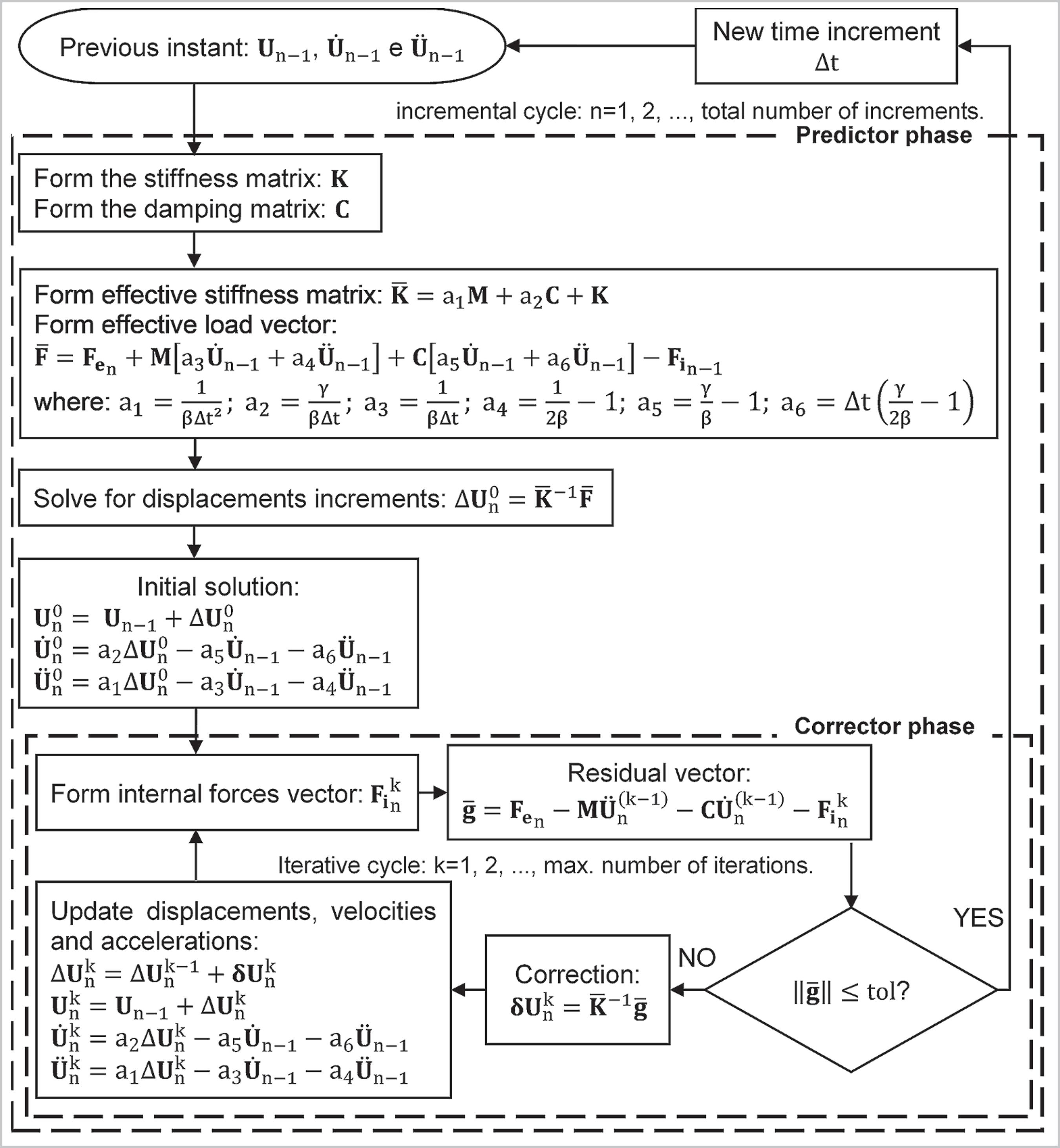
The transient response of the structure is obtained by solving Equation (15), which involves the use of a time integration algorithm. The procedure shown herein for calculating transient response combines the Newmark method (γ=0.5 and β=0.25) with Newton-Raphson iterations. This procedure is illustrated in Figure 2.
It is important to emphasize that the damping matrix is considered proportional to the mass and stiffness matrices, which means that:
where α0 and α1 are the Rayleigh coefficients, which are calculated with the adoption of an appropriate damping ratio (ξ). Cook et al. (1989)COOK, R. D.; MALKUS, D. S.; PLESHA, M. E. Concepts and applications of finite element analysis. 3. ed. [s.l.] John Wiley & Sons, 1989. state that, for steel structures, this damping ratio can vary from 0.5% to 5%.
4. Optimization problem
The goal of the optimization problem studied in this research is to determine the cross-sectional areas that will minimize the weight of the structure, imposing constraints on nodal displacements and axial stresses.
Therefore, the optimization problem can be expressed as:
Find
that minimizes
subjected to:
where A is the vector of design variables; f is the objective function, that calculates the structure weight by adding up the weights of each bar; nb represents the total number of bars of the structure; ρ is the density (given in kg/m3); Ai is the cross-sectional area of bar i; Li is the length of bar i; σTmax and σcmax are the maximum values of tensive and compressive axial stresses, respectively, acting in the structure; σTlim and σclim are the limiting values allowed for tensive and compressive axial stresses, respectively; Umax is the maximum absolute value of nodal displacement suffered by the structure; Ulim is the limiting value allowed for nodal displacement; and Amin and Amax are the lower and upper limits for the design variables, respectively.
In Equations (19) to (21), Umax, σTmax and σcmax are nonlinear functions of the design variables and are calculated performing a geometrically nonlinear dynamic analysis at each iteration of the optimization process. Figure 2 presented the nonlinear dynamic analysis procedure used herein.
5. Implementation
To achieve the goal of this study, a set of computational routines was performed using MATLAB (version R20116a). The routines were able to:
• Carry out the geometrically nonlinear analysis of trusses, using the analysis procedure explained in Section 3.
• Solve the optimization problem presented in Section 4, using the SQP method.
SQP was chosen for being one of the most used method for solving problems with nonlinear constraints, as is the case of the optimization problem studied herein. It should be noted that the SQP algorithm used is the one available on MATLAB’s Optimization ToolboxTM. It is accessed by MATLAB’s function fmincon, which automatically performs the derivatives of the objective function and constraint functions.
6. Numerical results
This section contains the presentation and discussion of four examples.
In the first two examples, the analysis procedure explained in Section 3 is used for calculating the transient response of space trusses. The results obtained are compared with solutions available in literature and with results generated by the ANSYS® software (version 18.2). These examples aim to validate the geometrically nonlinear dynamic analysis procedure used during the optimization process.
In the two following examples, the optimization routine is applied in order to solve the optimization problem presented in Section 4. In them, the lower and upper limits chosen for the design variables were 3.04 cm2 and 260 cm2, respectively; the limiting values allowed for nodal displacement were established as a fraction of the span of the structure, based on recommendations of Brazilian normative codes (ABNT NBR 8800 2008ASSOCIAÇÃO BRASILEIRA DE NORMAS TÉCNICAS. ABNT NBR 8800: Projeto de estruturas de aço e de estruturas mistas de aço e concreto de edifícios. Rio de Janeiro: ABNT, 2008.); and the limiting values allowed for stresses were defined as:
where fy is the yield stress, and γa1 is a reduction coefficient equal to 1.1.
For both optimization examples, the same physical and mechanical properties were adopted, which are: yield stress fy =250 MPa, modulus of elasticity E=200 GPa and density ρ=7850 kg/m3.
To define the initial designs for the optimization problems, several tests were performed. For each initial design tested, first a geometrically nonlinear dynamic analysis was performed to verify the nonlinear behavior and then an optimization convergency test was perfirmed. The initial designs adopted were the ones that presented stresses and nodal displacements closest to the limiting values imposed.
6.1 Geodesic dome: validation of the geometrically nonlinear dynamic analysis
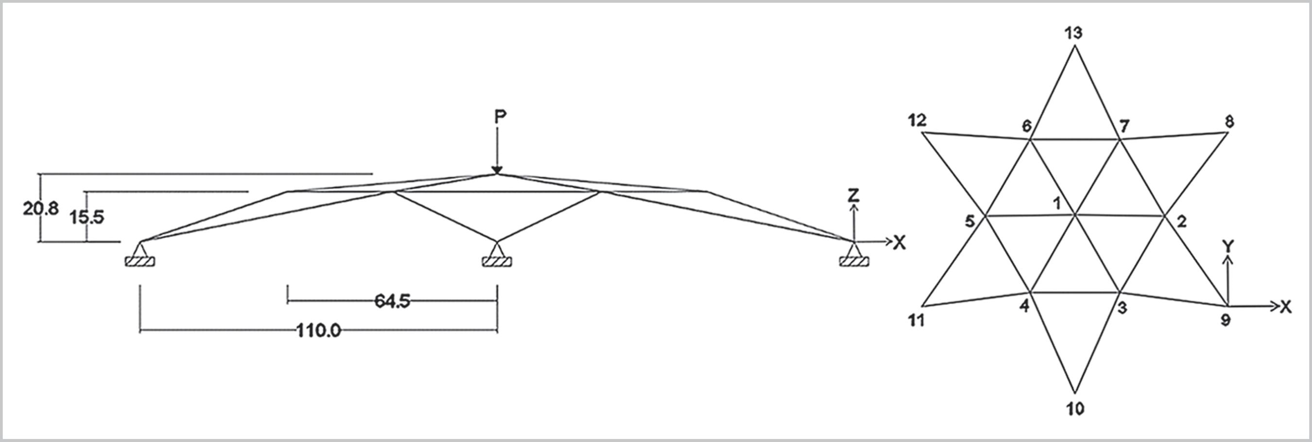
The first example is a geodesic dome with 24 bars and 13 nodes (Figure 3). Nodes 1 to 7 are free to move and nodes 8 to 13 are fixed. All bars have modulus of elasticity E = 68992 MPa, density ρ = 2760 kg/m3 and cross-sectional area A = 6.45 cm2. The structure is subjected to the triangular load shown in Figure 4a (P = 8.9 kN and Td = 0.01 s).
This example was previously studied by Zhu et al. (1994)ZHU, K.; AL-BERMANI, F. G. A.; KITIPORNCHAI, S. Nonlinear dynamic analysis of lattice structures. Computers & Structures, v. 52, n. 1, p. 9-15, 1994. and Wang et al. (2006)WANG, C.-Y.; WANG, R.-Z.; CHUANG, C.-C.; WU, T.-Y. Nonlinear dynamic analysis of reticulated space truss structures. Journal of Mechanics, v. 22, n. 3, p. 199-212, 2006.. As was done in these references, the geometrically nonlinear dynamic analysis performed in this case used a time step Δt=1.56×10⁻⁴ s and did not apply damping (ξ = 0%). Figure 4b shows a good agreement between the transient response of node 1 obtained in this study and the ones presented in literature.
6.2 Latticed beam: validation of the geometrically nonlinear dynamic analysis
Figure 5 shows a latticed beam with 76 bars and 28 nodes, and Figure 6a shows the load used in this analysis (P = 50 kN). The modulus of elasticity is E=71700 MPa, and the density is ρ=4152 kg/m3. For group 1 the cross-sectional area is A=0.8 cm2, for group 2 A=0.6 cm2 and for group 3 A=0.4 cm2. Nodes 1, 7, 8, 14, 15, 21, 22 and 28 are fixed.
In the geometrically nonlinear dynamic analysis, a time step Δt=10-5 s was used. In Figure 6b, the transient response obtained for node 10 is compared with the one generated by the ANSYS® software. A good agreement was achieved for both the undamped (ξ = 0%) and damped (ξ = 5%) cases.
6.3 Geodesic dome: optimization
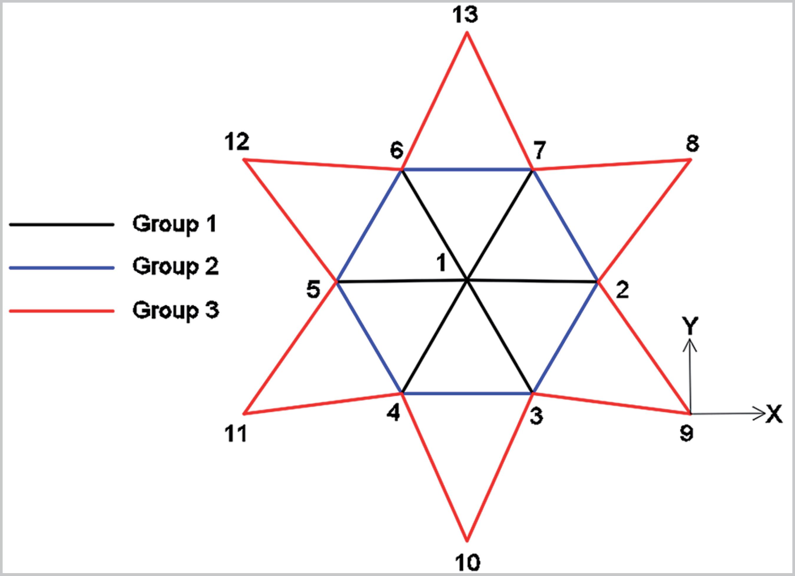
The first optimization example is the geodesic dome. Its geometry and applied loads were presented in Figure 3 and Figure 4a. For this example, P = 356 kN and Td = 0.1 s. Three groups of bars are considered, as shown in Figure 7.
The limiting value allowed for nodal displacement is 0.007 m, and the limiting value allowed for tensive and compressive stresses is 227 MPa. For the dynamic analysis performed in the optimization process, a duration of 0.1 s and a time step Δt = 0.0001 s were adopted. The initial design and the optimization results obtained for different values of damping ratio are shown in Table 1.
When analyzing the results, it can be observed that the undamped optimized structure is 38% lighter than the initial design. The use of damping does not generate a significant reduction of weight. With ξ = 0.5%, the structure is only 0.8% lighter than the one obtained for the undamped case. When the damping ratio is increased to 5%, the structure becomes 6.4% lighter than the one obtained with ξ = 0%.
6.4 Latticed beam: optimization
The second optimization example is the latticed beam. Its geometry, applied loads and groups of bars considered were presented in Figure 5 and Figure 6a. For this example, P = 100 kN.
The limiting value allowed for nodal displacement is 0.034 m, and the limiting value allowed for tensive and compressive stresses is 227 MPa. For the dynamic analysis carried out in the optimization process, a duration of 0.5 s and a time step Δt = 0.001 s are adopted. The initial design and the optimization results obtained for different values of damping ratio are shown in Table 2.
Analyzing the results, it can be observed that the undamped optimized structure is 17% lighter than the initial design. The use of a rather small damping ratio such as 0.5%, is enough to generate a significant reduction of weight in comparison with the undamped case, of 10%. When the damping ratio is increased to 5%, the structure becomes approximately 19% lighter than the one obtained with ξ = 0%.
7. Conclusions
In this research, a set of computational routines were performed in MATLAB to study the optimization of geometrically nonlinear truss structures subjected to dynamic loading, using the SQP algorithm available on MATLAB’s Optimization ToolboxTM. The formulated optimization problem sought to determine the cross-sectional areas that would minimize the weight of the structure, imposing constraints on nodal displacements and axial stresses.
As these constraints imply the performing of a geometrically nonlinear dynamic analysis at each iteration of the optimization process, the first two examples (Sections 6.1 and 6.2) were dedicated to validating this analysis procedure. The transient response of the space trusses was calculated, and the results obtained were consistent with solutions available in literature and with results generated by the ANSYS® software. Therefore, the analysis procedure is considered validated.
In Sections 6.3 and 6.4, the optimization process was used in order to study space trusses. For both example, results showed a significant reduction of weight with ξ = 0% in comparison with the initial design. Furthermore, the use of damping generated an additional reduction of weight. The latticed beam became 10% lighter with ξ = 0.5% than with ξ = 0%, and 19% lighter with ξ = 5% than with ξ = 0%. The geodesic dome became 0.8% lighter with ξ = 0.5% than with ξ = 0%, and 6.4% lighter with ξ = 5% than with ξ = 0%. This reduction of weight was not as substantial for the geodesic dome due to it being a stronger unstable structure.
References
- ALVES, E. C. Optimization of structures subject to dynamic load: deterministic and probabilistic methods. REM - Revista Escola de Minas, v. 69, n. 3, p. 281-286, 2016.
- ALVES, E. C.; VAZ, L. E. Optimum design of plates structures under random loadings. REM - Revista Escola de Minas , v. 66, n. 1, p. 41-47, 2013.
- ASSOCIAÇÃO BRASILEIRA DE NORMAS TÉCNICAS. ABNT NBR 8800: Projeto de estruturas de aço e de estruturas mistas de aço e concreto de edifícios. Rio de Janeiro: ABNT, 2008.
- AZAD, S. K.; BYBORDIANI, M.; AZAD, S. K.; JAWAD, F. K. J. Simultaneous size and geometry optimization of steel trusses under dynamic excitations. Structural and Multidisciplinary Optimization, v. 58, p. 2545-2563, 2018.
- CHEN, T.-Y. Design optimization with static and dynamic displacement constraints. Structural Optimization, v. 4, n. 3-4, p. 179-185, 1992.
- COOK, R. D.; MALKUS, D. S.; PLESHA, M. E. Concepts and applications of finite element analysis 3. ed. [s.l.] John Wiley & Sons, 1989.
- CRISFIELD, M. A. Non-linear finite element analysis of solids and structures Chichester: John Wiley & Sons, 1991. v. 1.
- HRINDA, G. A.; NGUYEN, D. T. Optimization of stability-constrained geometrically nonlinear shallow trusses using an arc length sparse method with a strain energy density approach. Finite Elements in Analysis and Design, v. 44, n. 15, p. 933-950, 2008.
- KASSIMALI, A.; BIDHENDI, E. Stability of trusses under dynamic loads. Computers & Structures, v. 29, n. 3, p. 381-392, 1988.
- KOCER, F. Y.; ARORA, J. S. Optimal Design of Latticed Towers Subjected to Earthquake Loading. Journal of Structural Engineering, v. 128, n. 2, p. 197-204, 2002.
- NOOR, A. K.; PETERS, J. M. Nonlinear dynamic analysis of space trusses. Computer Methods in Applied Mechanics and Engineering, v. 21, n. 2, p. 131-151, 1980.
- OHNO, T.; KRAMER, G. J. E.; GRIERSON, D. E. Least-weight design of frameworks under multiple dynamic loads. Structural Optimization , v. 1, n. 3, p. 181-191, 1989.
- PYRZ, M. Discrete optimization of geometrically nonlinear truss structures under stability constraints. Structural Optimization , v. 2, n. 2, p. 125-131, 1990.
- SAKA, M. P.; ULKER, M. Optimum design of geometrically nonlinear space trusses. Computers & Structures , v. 42, n. 3, p. 289-299, 1992.
- SHI, H.; SALIM, H.; SHI, Y.; WEI, F. Geometric and material nonlinear static and dynamic analysis of space truss structures. Mechanics Based Design of Structures and Machines, v. 43, p. 38-56, 2015.
- SULEMAN, A.; SEDAGHATI, R. Benchmark case studies in optimization of geometrically nonlinear structures. Structural and Multidisciplinary Optimization , v. 30, n. 4, p. 273-296, 2005.
- WANG, C.-Y.; WANG, R.-Z.; CHUANG, C.-C.; WU, T.-Y. Nonlinear dynamic analysis of reticulated space truss structures. Journal of Mechanics, v. 22, n. 3, p. 199-212, 2006.
- YANG, Y.-B.; KUO, S.-R. Theory and analysis of nonlinear framed structures New York: Prentice Hall, 1994.
- ZHU, K.; AL-BERMANI, F. G. A.; KITIPORNCHAI, S. Nonlinear dynamic analysis of lattice structures. Computers & Structures, v. 52, n. 1, p. 9-15, 1994.
Publication Dates
-
Publication in this collection
22 June 2020 -
Date of issue
Jul-Sep 2020
History
-
Received
24 July 2019 -
Accepted
21 Feb 2020