Abstract
Loratorial tests with pervious concrete comprised porosity and hydraulic conductivity as well as mechanical parameters as compressive, indirect tensile and bending strengths besides assessing its static and dynamic elasticity moduli. Later, a pervious sidewalk area of 1.0 x 8.65 square meters was built in order to determine the variation of the infiltration rate along time; over such experimental sidewalk, impact deflection tests performed allowed to assess back calculated moduli of the pervious concrete layer, resulting 33% to 13% lower than conventional concretes. A mechanistic analysis allowed to estimate the required thickness of concrete for heavy- and light-traffic areas. Tests disclosed no significant difference among the different concrete mixes, with 25% porosity and 0,1 cm/s permeability. Initial sidewalk infiltration rate of 0.5 cm/s dropped 50% four months after construction. It was verified that pervious concrete thicknesses for trucks and buses use are far higher than conventional concrete pavements.
Keywords:
Pervious concrete; Sidewalks; Bikeways; Mechanical responses; Hydraulic parameters; Mechanical parameters; Clogging
Resumo
Testes laboratoriais com concreto permeável incluíram medidas de porosidade e condutividade hidráulica, bem como parâmetros mecânicos - resistência à tração, tração indireta e flexão - além de avaliar seus módulos de elasticidade estático e dinâmico. Posteriormente uma área permeável na calçada de 1,0 x 8,65 metros quadrados foi construída para determinar a variação da taxa de infiltração ao longo do tempo; nesse experimento mediram-se deflexões de impacto na calçada, tendo sido avaliados os módulos retroanalisados da camada de concreto permeável, resultando 33% a 13% abaixo dos concretos convencionais. Uma análise mecanicista permitiu estimativa da espessura para o concreto em áreas de tráfego pesado e leve. Os testes apontaram não haver diferenças significativas entre as misturas estudadas, tendo porosidade de 25% permeabilidade de 0,1 cm/s. A taxa de infiltração inicial na calçada de 0.5 cm/s caiu 50% após quatro meses. Verificou-se que são requeridas maiores espessuras de concreto permeáveis que de concretos convencionais para sua aplicação para veículos comerciais.
Palavras-chave:
Concreto permeável; Calçadas; Ciclovias; Parâmetros hidráulicos; Parâmetros mecânicos; Entupimento
Introduction
The increase of paving impermeable surface areas has significant impacts on the hydrologic cycle, raising the peak runoff rate and increasing the likelihood of downstream flooding and inundation in cities (BOOTH; HARTLEY; JACKSON, 2002BOOTH, D.B.; HARTLEY, D.; JACKSON, R. Forest cover, impervious-surface area, and the mitigation of stormwater impacts. Journal of the American Water Resources Association, v. 38, n. 3, p. 835-845, 2002.). In recent years an alternative hydrological control concept has gained place in several countries related to sustainable urban drainage development. Low Impact Development (LID) is a suite of stormwater control best management practices (BMPs) that aims to direct stormwater to be controlled, as near as possible to its source, avoiding runoff and consequently downstream flooding. LID tries to mimic natural hydrologic cycles using processes such as infiltration, evaporation, flowpath disruption and detention (DIETZ, 2007DIETZ, M. E. Low impact development practices: a review of current research and recommendations for future directions. Water, Air, and Soil Pollution, v. 186, n. 1, p. 351-363, 2007.). Much of the runoff comes from roads, highway, bus corridors, parking lots and other infrastructures in large urban centers. Restrictions on stormwaters are being imposed by governmental transportation and environmental agencies. With respect to environmental criteria, regulations have been created in Brazil in order to restrict the percentage of surface impermeable surface areas in urban projects (PREFEITURA…, 2016PREFEITURA DO MUNICÍPIO DE SÃO PAULO. Lei Nº 16.402. Diário Oficial do Município de São Paulo, 22 de março de 2016.). Usually, at least 30% of the total construction area for transportation infrastructure design projects is required to be permeable. Permeable pavements systems can provide mechanical and hydraulic characteristics to withstand the traffic loads, and allow the stormwater to infiltrate through its structure, reducing runoff and at the same time fulfilling the permeable area requirement for a given construction site.
Pervious concrete is one of the main drainable materials used as the surface layer of permeable pavements. It consists of a carefully controlled amount of paste with an aggregate system defined by a narrow particle size distribution and little or no amount of sand and fines (SCHAEFER et al., 2010SCHAEFER, V. R. et al. Construction and performance of pervious concrete overlay at minnesota road research project. Transportation Research Record: Journal of Transportation Research Board, TRR 2164, p. 82-88, 2010.) with porosities varying from 15% to 30%, this material allows water to infiltrate through its porous structure, helping to reduce the stormwater runoff from the pavements. Due to the high porosity, the mechanical resistance of pervious concrete tends to be lower when compared to conventional concretes used for pavements. This condition restricts its use as surface layers for permeable pavements in parking areas, sidewalks, bikeways, and light-vehicle traffic areas.
In view of the possible benefits of this technology, the main goal of this research was to develop and determine the main characteristics of three different mixtures of pervious concrete varying the aggregate gradation, and then verifying its behavior to be used as the surface layer of permeable sidewalks. The study was carried out by initially casting concrete specimens in the laboratory and assessing its porosity, hydraulic conductivity, compressive, indirect tensile and flexural strengths, as well as static and dynamic moduli of elasticity. Afterwards, a short sidewalk was built to investigate variability of hydraulic time-related performance in a dense tropical garden as well as the pavement response to loads. A mechanistic analysis was then developed using the finite element software EverFE 2.25 (DAVIDS et al., 2003DAVIDS, W.G. et al. Three-dimensional finite element analysis of jointed plain concrete pavement with EverFE 2.2. Transportation Research Record: Journal of the Transportation Research Board, TRR 1853, p. 92-99, 2003.) in order to estimate the required thickness of the pervious concrete surface layer for both heavy and light-traffic uses.
Materials and methods
The following subsections summarize the description of materials, mix proportions, laboratory tests and numerical approach used during the research.
Materials
Aggregates
A coarse rounded granite aggregate with grain size ranging from 4.75 mm to 12.5 mm in diameter was used for producing the concrete mixes, resulting from the sieving of a commercial aggregate supplier.
Cement
Sulfate Resistant Portland Cement CP III 40 RS as specified by NBR 16697 (ABNT, 2018ASSOCIAÇÃO BRASILEIRA DE NORMAS TÉCNICAS. NBR 16697: cimento Portland: requisitos. Rio de Janeiro, 2018.) was used as the cementitious material in pervious concrete; this hydraulic cement type contains up to 70% of grounded blast furnace slags. Some CP III cement physical data are given in Table 1. The reason for such a choice was to specify a sustainable binder with enough resistance to sulfates due the peculiarities of pervious concrete performance requirements.
Physical description of the slag cement (HOLCIM…, 2010HOLCIM BRAZIL. Relatório de Caracterização do Cimento pelo Fabricante. 2010.)
Concrete mix design
The mix designs for the tested concretes used for this study were founded upon a literature review (MCCAIN; DEWOOLKAR, 2010MCCAIN, G. N.; DEWOOLKAR, M. M. Porousconcrete pavements. Transportation Research Record: Journal of the Transportation Research Board , TRR 2164, p.66-75, 2010.) since there was no specific mix design official procedure for pervious concrete at the time of this study. Three mix designs (named M1, M2 and M3) were produced using different coarse aggregate gradations, as shown in Table 2. Table 3 depicts the material proportions used.
Specimens preparation and laboratory tests
Cylindrical (200 mm by 100 mm) and prismatic (100 mm x100 mm x 400 mm) molds were used to prepare the pervious concrete specimens; cylindrical specimens were casted by rodding 15 times over each of three layers; for prismatic specimens the compaction consisted of rodding 25 times over each of the two layers. For both cases after compaction vibration was applied during 10 seconds (using a vibration table). The specimens (not capped) were demolded after 7 days; they were maintained in wet chamber 28 days before running the tests.
Porosity and density control tests
Porosity of specimens was assessed using C1754/C1754M (AMERICAN…, 2012aAMERICAN SOCIETY FOR TESTING AND MATERIALS. C1754/C1754M: standard test method for density and void content of hardened pervious concrete. West Conshohocken, 2012a.; MONTES; VALAVALA; HASELBACH, 2005MONTES, F.; VALAVALA, S.; HASELBACH, L. M. A new test method for porosity measurements of Portland cement pervious concrete. Journal of ASTM International, v. 2, n. 1, 2005.) by calculating the difference between the dry mass and the submerged mass under water. For, the specimens were placed in oven at 105 ºC for 24 h before measuring their dry weight. Then, the dried specimens were submerged for 30 minutes and the submerged weight was obtained.
Compressive strength test
The compressive strength of cylindrical specimens was measured according to C39/C39M (AMERICAN…, 2016aAMERICAN SOCIETY FOR TESTING AND MATERIALS. C39/C39M: standard test method for compressive strength of cylindrical concrete specimens. West Conshohocken, 2016a.). Top and bottom surfaces of the specimens were cut before being placed in the loading frame. Equivalent loading speed was held around 0.30 MPa/s which is in the range of 0.15-0.35 MPa/s as per the standard. Failure was considered to be the ultimate load applied to the sample before it could no longer support further loading.
Splitting tensile strength test
The splitting tensile strength of the cylindrical samples was measured according to the C496/C496M (AMERICAN…, 2011AMERICAN SOCIETY FOR TESTING AND MATERIALS. C496/C496M: standard test method for splitting tensile strength of cylindrical concrete specimens. West Conshohocken, 2011.). Equivalent loading speed was held around 1 MPa/s which, according to the relative standard, is in the range of 0.7-1.4 MPa/s.
Flexural strength test and static elasticity modulus
The flexural strength of the prismatic specimens was measured according to C78/C78M (AMERICAN…, 2016bAMERICAN SOCIETY FOR TESTING AND MATERIALS. C78/C78M: standard test method for flexural strength of concrete (using simple beam with third-point loading). West Conshohocken, 2016b.). Equivalent loading speed was held around 0.98 MPa/s, which according to the relative standard, is in the range of 0.86-1.12 MPa/s. The static secant modulus of elasticity was obtained through the Mohr’s analogy from the flexural test according to C580-02 (AMERICAN…, 2012bAMERICAN SOCIETY FOR TESTING AND MATERIALS. C580-02: standard test method for flexural strength and modulus of elasticity of chemical-resistant mortars, grouts, monolithic surfacings, and polymer concretes. West Conshohocken, 2012b.). using a Linear Variable Differential Transformer (LVDT), assuming the span measured for an application of 70% of the rupture load.
Dynamic modulus of elasticity
Dynamic modulus of elasticity was measured only for the cylindrical samples by determining the propagation velocity of longitudinal wave pulses through the concrete. The test and calculations were carried out according to the C597 (AMERICAN…, 2016cAMERICAN SOCIETY FOR TESTING AND MATERIALS. C597-16: standard test method for pulse velocity through concrete. West Conshohocken, 2016c.).
Permeability tests
Two different permeability tests under saturated conditions were carried out for this research: falling and constant head permeability tests. The falling head permeability test was performed using a special apparatus designed specifically for this research. Average permeability is calculated according based on Darcy’s law and laminar flow assumption as used by Montes and Haselbach (2006MONTES, F.; HASELBACH, L. Measuring hydraulic conductivity in pervious concrete. Environmental Engineering Science, v. 23, p.960-969, 2006.).
The constant head permeameter test was carried out according D2434-68 (AMERICAN…, 2006AMERICAN SOCIETY FOR TESTING AND MATERIALS. D2434-68: standard test method for permeability of granular soils (Constant Head). West Conshohocken, 2006.) which was originally designed for granular soils with high permeability and is based on a constant water column height. This granular-material hydraulic behavior may be closer to the behavior of the pervious concrete, which also has a high permeability.
Sidewalk placement and tests in the field
Layers materials and placement procedures
After defining the concrete mixture, an experimental sidewalk with dimensions of 1.0 m x 8.65 m was built in order to determine the variation of the initial infiltration rate (and consequent clogging potential in the field), as well as the deflection basin of the structure under dynamic loads for pervious concrete layer modulus backcalculation. The structure used the M1 laboratory mix with slight modified grain distribution (Figure 1) and was built as 10 cm-thick surface layer; for such a concrete mix it was added 1.235 mL/m³ of viscosity modifier (superplasticizer) to control the workability of the fresh concrete. Pervious concrete surface was placed over a 15 cm-thick base layer of recycled construction aggregate from demolition waste (RCA); the open-graded RCA gradation is presented in Figure 2, which is similar to the AASHTO #57 coarse aggregate, commonly used for the base layer of permeable pavements (AMERICAN…, 2015AMERICAN SOCIETY OF CIVIL ENGINEERS. Permeable Pavements. Permeable Pavement Task Committee, 2015.).
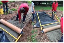
The subgrade and the base layer surfaces were leveled, but neither of them was compacted in the field, in order to guarantee the highest permeability possible for the system. A steel roller with the capability of applying a pressure of 0.07 MPa was used to consolidate and finish the pervious concrete layer. Right after rolling and finishing the surface, an impermeable polyethylene sheet cover was used over the pervious concrete for seven days in order to avoid high water evaporation, therefore aiding the cement hydration process (Figure 3).
Field tests
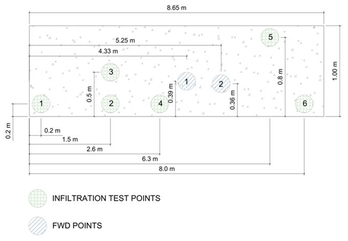
The unsaturated surface infiltration tests were performed according C1701/C1701M (AMERICAN…, 2009AMERICAN SOCIETY FOR TESTING AND MATERIALS. C1701/C1701M: standard test method for infiltration rate of in place pervious concrete. West Conshohocken, 2009.) at six locations over the sidewalk. The deflections rebound of the pervious concrete sidewalk was measured in two points using a Falling Weight Deflectometer (FWD) test according to STP 1375-EB (KHAZANOVICH, 2000KHAZANOVICH, L. Dynamic analysis of FWD test results for rigid pavements. Nondestructive Testing of Pavements and Backcalculation of Moduli Third Volume, American Society for Testing and Materials, ASTM STP1375:, West Conshohocken, 2000.). FWD sensors were located at the prescribed interval of 0, 20, 30, 45, 60, 90 and 120 cm from the center of the load. The FWD load of 41 kN was dropped in two different locations across the sidewalk surface. The load was dropped onto a plate with a radius of 15 cm. Locations for such tests are presented in Figure 4.

Comparison of coarse aggregate gradations of mixture M1 and the pervious concrete used for the sidewalk placement


Mechanistic analysis
The behavior of conventional rigid pavements is classically modeled by Westergaard theory of a medium-thick plate resting on a Winkler dense liquid foundation (IOANNIDES, 1990IOANNIDES, A. M. Extension of Westergaard solutions using dimensional analysis. In: INTERNATIONAL WORKSHOP ON THE THEORETICAL DESIGN OF CONCRETE PAVEMENTS, 2., Siguenza, 1990. Proceedings… Siguenza, 1990.). The Westergaard solution and the dense liquid foundations method have been tested on pervious concrete pavements using field deflection measurements to backcalculate elastic parameters of pervious concrete and the results showed that the model represents the behavior of pervious concrete pavements fairly well (VANCURA; MACDONLAD; KHAZANOVICH, 2011VANCURA, M.; MACDONALD, K.; KHAZANOVICH, L. Structural analysis of pervious concrete pavements. Transportation Research Record: Journal of the Transportation Research Board , TRR 2226, p.13-20, 2011.) For the current analysis, simulations were carried out by using the 3D FEM-based EverFE Version 2.25 considering plate supported by a dense liquid foundation model.
Two different types of vehicles axles were used for the proposed analyses: an 80-kN four-wheel axle to simulate the common standard axle for road pavement design; and a 22-kN two-wheel axle loading to simulate the loading effects of a commercial van traveling on the pavement structure of a parking lot. For both axles, a tire pressure of 0.7 MPa was assigned for each wheel. The first step of the mechanistic analysis was to test the wheel loadings in several positions over the idealized 3,5 m x 5,0 m slab, in order to find out the most critical loading position for further analysis. Since the model considers a medium-thick slab resting on a Winkler’s foundation, both base and subgrade layers were modeled assuming a given modulus of subgrade reaction (k-value) of 0.05 MPa/mm, so the slab was considered to be placed right over the dense liquid foundation.
The strength and elastic parameters chosen for pervious concrete were based on the average results obtained from the laboratory tests. Exception for the Poisson’s ratio, which was estimated based on a former research with similar pervious concrete mixtures and porosities (GOEDE, 2009GOEDE, W.G. Pervious concrete: investigation into structural performance and evaluation of the applicability of existing thickness design methods. Thesis (MSc), Washington State University, Pullman, 2009.). For conventional concrete parameters were based on common practices. The values assumed for the parameters of the pervious and conventional concrete are shown in Table 4.
Currently, there is no a field-calibrated fatigue transfer function specifically developed for pervious concretes; so, two different approaches were used in order to compare the structural behavior of both permeable and conventional pavements, and to estimate the thickness of the slabs. First, the design thickness for each loading case and material was based on the Portland Cement Association procedure for rigid pavement design (PORTLAND…, 1984PORTLAND CEMENT ASSOCIATION. Thickness design for concrete highways and street pavements. EB 109.01P, Skokie, 1984.) which assumes that the pavement stress-strength ratio (SSR), which is defined as the ratio between equivalent critical tensile stress (σequiv) on the bottom of the slab and the modulus of rupture of the material (MR) must be less than 0.45 (in order to reach an unlimited number of load repetitions). Second, since it was found that the Westergaard’s model was able to model the behavior of pervious concrete (VANCURA; MACDONALD; KHAZANOVICH, 2011VANCURA, M.; MACDONALD, K.; KHAZANOVICH, L. Structural analysis of pervious concrete pavements. Transportation Research Record: Journal of the Transportation Research Board , TRR 2226, p.13-20, 2011.), it was suggested to adopt the StreetPave fatigue model for the analysis of the pervious concrete, which was developed for the American Concrete Paving Association’s (ACPA) StreetPave pavement design software (TITUS-GLOVER et al.,2005TITUS-GLOVER, L. et al. Enhanced portland cement concrete fatigue model for Street Pave. Transportation Research Record: Journal of the Transportation Research Board , TRR 1919, p. 29-37, 2005.). The StreetPave fatigue model is shown in Equation 1 and was used in order to determine the number of allowable load repetitions for each axle and material.
Where:
Nf is the number of allowable load repetitions;
SSR is the pavement stress-strength ratio (σequiv/MR); and
P is the probability of failure, which was specified as 50% in the fatigue calculations.
Results analysis and discussion
Laboratory results for pervious concrete mixes
Tables 5 and 6 summarize all the laboratory results statistics and the number of specimens tested for each parameter for the studied mixes. Number of specimens for compressive strength were low due to unusual concern of such a parameter for pavement design, construction and technological control since design strength for plain concrete slabs is flexural resistance as bending or hinging due to loads and curling are typical structural response. It can be observed that the change on coarse aggregate gradation of mixes did not cause any significant effects on the mechanical behavior of the pervious concrete, since all the average results are quite similar. This situation can be related to the narrow range variation for porosity results (23% to 26%), since the porosity affects all the other properties of the material (HASELBACH; FREEMAN, 2006HASELBACH, L.; FREEMAN, R. Vertical porosity distributions in pervious concrete pavement. ACI Materials Journal, v. 103, n. 6, p. 452-458, 2006.). For the flexural strength and static modulus of elasticity, the results were approximately 2.1 MPa and 16 GPa, respectively, which is considerably lower than the values of conventional concretes used for paving. Hence, low strength (50% of the strength of conventional concrete) of pervious concrete with high porosity (around 25%) would certainly results in a greater slab thickness, which could restrict its use to light-traffic applications due to investment-costs issues. For the compressive and tensile strengths, average results 8.0 MPa and 1.4 MPa, respectively. Ratio between compressive strength and flexural strength of the porous concrete is around 4 in this study, two times less than normally retained for plastic concretes for paving.
There are many studies (old and recent) identifying pervious concrete (with 5% to 35% porosity) mechanical parameters, as early disclosed by some of them as follows: specific gravity of 16 to 23.9 kN/m3 (TENNIS; LEMING; AKERS, 2004TENNIS, P.vD.; LEMING, M.vL.; AKERS, D. J. Pervious concrete pavements. Skokie: Portland Cement Association, 2004. EB302.; BEELDENS, 2001BEELDENS, A. Behaviour of porous PCC under freeze thaw cycling. In: INTERNATIONAL CONGRESS ON POLYMERS IN CONCRETE, 10.,Honolulu, 2001. Proceedings… Honolulu, 2001.; LEE et al., 2009LEE, M. G. et al. Experimental study of pervious concrete on parking lot. Proceedings of the GeoHunan International Conference, v. 193, n. 20, p. 125-131, 2009.; HENDERSON; TIGHE; NORRIS, 2009HENDERSON, V.; TIGHE, S.L.; NORRIS, J. Pervious concrete pavement: integrated laboratory and field study. Transportation Research Record: Journal of the Transportation Research Board , v. 2113, n. 1, 2009.; BATEZINI; BALBO, 2015BATEZINI, R.; BALBO, J. T. Estudo da condutividade hidráulica com carga constante e variável em concretos permeáveis. Revista IBRACON de Estruturas e Materiais,v. 8, n. 3, p.248-259, 2015.); flexural strength varying between 1.0 to 7.5 MPa (TENNIS; LEMING; AKERS, 2004TENNIS, P.vD.; LEMING, M.vL.; AKERS, D. J. Pervious concrete pavements. Skokie: Portland Cement Association, 2004. EB302.; Olek et al., 2003OLEK, J. et al. Development of quiet and durable porous Portland cement concrete paving materials. Final Report SQDH-5 Center of Advanced Cement Based Materials, Purdue, 2003. ; BEELDENS; VAN GEMERT; CAESTECKER, 2003BEELDENS, A.; VAN GEMERT, D.; CAESTECKER, C. Porous concrete: laboratory versus field experience. In: INTERNATIONAL SYMPOSIUM ON CONCRETE ROADS, 9., Istanbul, 2003. Proceedings… Istanbul, 2003.; BEELDENS, 2001BEELDENS, A. Behaviour of porous PCC under freeze thaw cycling. In: INTERNATIONAL CONGRESS ON POLYMERS IN CONCRETE, 10.,Honolulu, 2001. Proceedings… Honolulu, 2001.; KAJIO et al., 1998KAJIO, S. et al. Properties of porous concrete with high strength. In: INTERNATIONAL SYMPOSIUM ON CONCRETE ROADS, 8., Lisbon, 1998. Proceedings… Lisbon, 1998.; BATEZINI; BALDO, 2015BATEZINI, R.; BALBO, J. T. Estudo da condutividade hidráulica com carga constante e variável em concretos permeáveis. Revista IBRACON de Estruturas e Materiais,v. 8, n. 3, p.248-259, 2015.); compressive strength varying from 5.5 to 55.8 MPa (TENNIS; LEMING; AKERS, 2004TENNIS, P.vD.; LEMING, M.vL.; AKERS, D. J. Pervious concrete pavements. Skokie: Portland Cement Association, 2004. EB302.; BEELDENS; VAN GEMERT; CAESTECKER, 2003BEELDENS, A.; VAN GEMERT, D.; CAESTECKER, C. Porous concrete: laboratory versus field experience. In: INTERNATIONAL SYMPOSIUM ON CONCRETE ROADS, 9., Istanbul, 2003. Proceedings… Istanbul, 2003.; BEELDENS, 2001BEELDENS, A. Behaviour of porous PCC under freeze thaw cycling. In: INTERNATIONAL CONGRESS ON POLYMERS IN CONCRETE, 10.,Honolulu, 2001. Proceedings… Honolulu, 2001.; TAMAI; YOSHIDA, 2003TAMAI, M.; YOSHIDA, M. Durability of porous concrete. In: CANMET/ACI INTERNATIONAL CONFERENCE ON DURABILITY OF CONCRETE, 6., Thessaloniki, 2003. Proceedings… Thessaloniki: AmericanConcrete Institute, 2003.; PARK; TIA, 2004PARK, S. B.; TIA, M. An experimental study on the water-purification properties of porous concrete. Cement and Concrete Research, v. 34, p. 177-184, 2004.; ZAHARIEVA et al., 2003ZAHARIEVA, R. et al. Assessment of the surface permeation properties of recycled aggregate. Concrete Cement and Concrete Composites, v. 25, n. 2, p. 223-232, 2003.; PINDADO; AGUADO; JOSA, 1999PINDADO, M. Á.; AGUADO, A.; JOSA, A. Fatigue behavior of polymer-modified porous concretes. Cement and Concrete Research , v. 29, p. 1077-1083, 1999.; LEE et al., 2009LEE, M. G. et al. Experimental study of pervious concrete on parking lot. Proceedings of the GeoHunan International Conference, v. 193, n. 20, p. 125-131, 2009.; DELATTE; MRKAJIC; MILLER, 2009DELATTE, N.; MRKAJIC, A.;MILLER, D.I. Field and laboratory evaluation of pervious concrete pavements. Transportation Research Record: Journal of the Transportation Research Board , v. 2113, n. 1, 2009.; HUANG et al., 2010HUANG, B. et al. Laboratory evaluation of permeability and strength of polymer-modified pervious concrete. Construction and Building Materials , v. 24, p. 818-823, 2010.; Henderson; TIGHE; NORRIS, 2009HENDERSON, V.; TIGHE, S.L.; NORRIS, J. Pervious concrete pavement: integrated laboratory and field study. Transportation Research Record: Journal of the Transportation Research Board , v. 2113, n. 1, 2009.; BATEZINI; BALDO, 2015BATEZINI, R.; BALBO, J. T. Estudo da condutividade hidráulica com carga constante e variável em concretos permeáveis. Revista IBRACON de Estruturas e Materiais,v. 8, n. 3, p.248-259, 2015.). One shall note that compressive strength range in the mentioned studies are close related to cement consumption for pervious concrete mixtures. Values obtained in this study for such physical and mechanical parameters are then compatible to conventional range and coherent to the porosity of 25-26% for pervious concrete. It is worth note that the achieved flexural strength of the porous concrete mixtures complies the requirements under NBR 16416 (ABNT, 2015ASSOCIAÇÃO BRASILEIRA DE NORMAS TÉCNICAS. NBR 16416: revestimentos permeáveis de concreto: requisitos e procedimentos. Rio de Janeiro, 2015.) for light traffic of vehicles and as well as public parks and bikeways.
The dynamic modulus of elasticity average results were circa 23 GPa, which can be considered close to the values of the static modulus of elasticity for conventional dry concretes used for pavement bases and considerably higher than the static modulus of elasticity of pervious concrete (15 to 16 GPa). The meaning of dynamic modulus for concretes is still uncertain because it is known to be different (higher) from static modulus, since the concrete is expected to show a nonlinear dependence between stress and strain, even at low values of deformation caused by quasi-static tests and dynamic tests based on stress-wave propagation (POPOVICS; ZEMAJTIS; SHLOLNIK, 2008POPOVICS, J.S.; ZEMAJTIS, J.; SHLOLNIK, I. A study of static and dynamic modulus of elasticity of concrete. ACI-CRC Final Report, University of Illinois, Urbana, 2008.). Correlations have been developed in order to compare the static and dynamics modulus of elasticity for conventional and high strength concretes. These correlations normally show ratios between the modulus (static/dynamic) considering the static initial tangent modulus ranging from 75% (SHKOLNIK, 2005SHKOLNIK, I. E. Effect of nonlinear response of concrete on its elastic modulus and strength. Cement and Concrete Composities, v. 27, n. 7/8, p.747-757, 2005.) to 83% (NEVILLE, 1997NEVILLE, A. M. Properties of Concrete. 4thed. New York: John Wiley & Sons Inc., 1997.). The modulus ratio obtained herein was in average 70% and this difference may be associated with the way of defining value for a static modulus of elasticity herein used (secant, considering the span taken in 70% of the rupture stress), or due to the high porosity of the pervious concrete when compared with conventional or high strength concretes.
For the hydraulic conductivity the values were also similar for all the three mixes in both falling and constant head tests, indicating that the chosen (herein) variation of the coarse aggregate gradation does not seem to affect the hydraulic characteristics of the pervious concrete. The coefficient of permeability obtained for both permeability tests are within the range of results obtained by most former studies with values ranging between 0,01 cm/s and 1,5 cm/s (MONTES; HASELBACH, 2006MONTES, F.; HASELBACH, L. Measuring hydraulic conductivity in pervious concrete. Environmental Engineering Science, v. 23, p.960-969, 2006.; SCHAEFER et al., 2006SCHAEFER, V. R. et al. Mix design development for pervious concrete in cold climates. Ames: Iowa State University, 2006. Final Report.). It was also noticed that the average of the results obtained by the two tests appear to be different since the values for the falling head test were always higher; this may be attributed to the difference in equipment technology. For the falling head test the sample was wrapped in plastic film intending to reduce or limit lateral water flow. However, unlike the equipment used in the constant head permeameter, there was no external pressure applied to the lateral of the specimens as occurs in the constant head apparatus, which may have caused a considerable loss of water by the specimen laterals, resulting in higher hydraulic conductivity values.
Under the point of view of simple testing methods, both of them are fair and correct; there is no way to purge one of each other. The different results can be easily used on the basis of the design hypothesis for the rainwater reservoir. In one case, the reservoir can be designed for swallowing the total volume amount without stationary water accumulation over the surface, especially in case of permanent flow through the whole pavement structure to the path of underneath drains pipes, avoiding completely the need for considering charging or filling of the reservoir (pervious concrete plus permeable granular base). When the opposite is verified, hydraulic engineers can use the constant head permeability result for the design of the structure base on the highness of accumulated water over the surface to be slowly drained to subgrade after the storm; or use even a intermediate value between both of them (constant head and falling head tests) from its personal scrutinous based on the net pressure on the system.
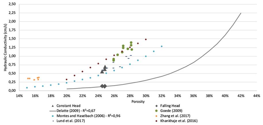
Figure 5 shows the variation of the hydraulic conductivity versus the void ratio variation of the two tests assessed in this study compared to former results ( MONTES; HASELBACH, 2006MONTES, F.; HASELBACH, L. Measuring hydraulic conductivity in pervious concrete. Environmental Engineering Science, v. 23, p.960-969, 2006.; DELATTE; MRKAJIC; MILLER, 2009DELATTE, N.; MRKAJIC, A.;MILLER, D.I. Field and laboratory evaluation of pervious concrete pavements. Transportation Research Record: Journal of the Transportation Research Board , v. 2113, n. 1, 2009.). It can be observed that the hydraulic conductivity values currently obtained are very similar to those obtained by Delatte, Mrkajic and Miller (2009DELATTE, N.; MRKAJIC, A.;MILLER, D.I. Field and laboratory evaluation of pervious concrete pavements. Transportation Research Record: Journal of the Transportation Research Board , v. 2113, n. 1, 2009.) in the case of the constant head test and porosity around 25%, approximately. However, Montes and Haselbach (2006MONTES, F.; HASELBACH, L. Measuring hydraulic conductivity in pervious concrete. Environmental Engineering Science, v. 23, p.960-969, 2006.) obtained values four to five times higher, which are equivalent to the results found out by the falling head tests herein, considering the same porosity. It must be pointed out that both studies used the saturated falling head test.
Another important observation is related to the coefficient of variation of the results, which seems to be always higher for destructive than for nondestructive tests. It can be also observed that the variations in the mechanical results are higher than those commonly obtained for regular plastic concretes (in lab). This situation is probably related to the higher porosity and porosity ranges of pervious concrete, which may directly influence the repeatability of tests.
Compared to other classic studies in pervious concrete hydraulic parameters measurements, one can observe coherent results when mentioning the paired values for porosity and hydraulic conductivity as follows, for instance:
-
15 - 25% leading to 0.20 - 0.53 cm/s (TENNIS; LEMING; AKERS,2004TENNIS, P.vD.; LEMING, M.vL.; AKERS, D. J. Pervious concrete pavements. Skokie: Portland Cement Association, 2004. EB302.);
-
11 - 15% leading to 0.03 - 0.18 cm/s (KAJIO et al., 1998KAJIO, S. et al. Properties of porous concrete with high strength. In: INTERNATIONAL SYMPOSIUM ON CONCRETE ROADS, 8., Lisbon, 1998. Proceedings… Lisbon, 1998.);
-
3 - 29% leading to 0.01 - 0.22 cm/s (LEE et al., 2009LEE, M. G. et al. Experimental study of pervious concrete on parking lot. Proceedings of the GeoHunan International Conference, v. 193, n. 20, p. 125-131, 2009.); and
-
5 - 35% leading to 0.01 - 1.0 cm/s (DELATTE; MRKAJIC; MILLER,2009DELATTE, N.; MRKAJIC, A.;MILLER, D.I. Field and laboratory evaluation of pervious concrete pavements. Transportation Research Record: Journal of the Transportation Research Board , v. 2113, n. 1, 2009.).
Is interesting to verify that present falling head test results agrees to trends found in classical Goede (2009GOEDE, W.G. Pervious concrete: investigation into structural performance and evaluation of the applicability of existing thickness design methods. Thesis (MSc), Washington State University, Pullman, 2009.) and Montes and Haselbach (2006MONTES, F.; HASELBACH, L. Measuring hydraulic conductivity in pervious concrete. Environmental Engineering Science, v. 23, p.960-969, 2006.) papers as well to recent Lund, Kevern and Schaefer (2017LUND, M.; KEVERN, J. V.; SCHAEFER, K. H. Mix Design for improved strength and freeze-thaw durability of pervious concrete fill in pearl-chain bridges. Materials and Structures, v. 50, n. 42, 2017.) studies. Zhang et al. (2017ZHANG, Z. et al. Influence of crushing index on proprieties of recycled aggregates pervious concrete. Construction and Building Materials , v. 135, p. 112-118, 2017.) results are restricted but by comparison to Delatte, Mrkajic and Miller (2009DELATTE, N.; MRKAJIC, A.;MILLER, D.I. Field and laboratory evaluation of pervious concrete pavements. Transportation Research Record: Journal of the Transportation Research Board , v. 2113, n. 1, 2009.) denotes tendency to low permeability coefficients with different tests; however, it is expected lower results for constant head tests, consenting the present results.

Permeability and stiffness of pervious concrete in the field
Before presenting the numerical values of tests performed over the sidewalk it is worth note to consider the surrounding field context. Figure 6 depicts the situation of the experimental sidewalk in relation to the abundant (both tropical and exotic) amount of trees in its surroundings.
It was observed that meanwhile the first infiltration tests (December 11th, 2015; 28 days after concrete placement) and the second data set (April 5th, 2016) the sidewalk surface was scarcely covered by leaves and the presence of decayed leaves on organic paste form happened, more likely allowing the penetration of decayed matter to the pervious concrete superficial porous structure, causing partial clogging on it. In Table 7 are shown the results of infiltration tests performed during the aforementioned dates. The results show that the surface infiltration rates in the field varied from 0.10 to 1.06 cm/s with an average of 0.54 cm/s 28 days after construction of the sidewalk, values similar to the results for hydraulic conductivity in laboratory for mixture M1, particularly comparing to falling head test results. After approximately four months, the surface infiltration rates dropped significantly, varying from 0.04 cm/s to 0.55 cm/s. The larger loss of permeability was observed at point 1, where the infiltration rate was reduced by 92% after only four months. The reduction is attributed to the clogging of the macro-pores due to the infiltration of dirt and organic matter through the top of the slab, into the concrete structure, as well as the presence of excessive organic matter from the falling leaves of nearby trees during the fall. However, valuating the results, they can be taken as favorable since pavements clogged after years of their construction presented infiltration rates greater than 0,01 cm/s, value considered reasonable for aged and clogged pervious concrete pavements in field studies carried out by the Hunt and Colllins (2008HUNT, W. F.; COLLINS, K. A. Permeable pavement: research update and design implications. Special Report, Department of Biological and Agricultural Engineering, North Carolina State University, 2008.).
Table 8 and Figure 7 present the backcalculated parameters of the structure using EverFE 2.25 based in the deflection envelopes, respectively. RMSE is the root mean square error calculated according to specification D5858 (AMERICAN…, 2015aAMERICAN SOCIETY FOR TESTING AND MATERIALS. D5858: standard guide for calculating in situ equivalent elastic moduli of pavement materials using layered elastic theory. West Conshohocken, 2015a.), as follows:
Where:
Tolerance recommended by ASTM standard RMSE is by 2%. One can see that results for both points of evaluation over the pervious concrete layer are fairly acceptable.
The field backcalculated modulus of elasticity of 17 GPa and 24 GPa are close to but higher than the static laboratory value of 16 GPa for mixture M1. This minor contrast in the results may be attributed to the difference in the types of loads applied which were static in the laboratory and dynamic in the field and which could have caused the modulus to increase due to the dynamic load application in the field when the time of pulsing load is very short. In former study (VANCURA; MACDONALD; KHAZANOVICH, 2011VANCURA, M.; MACDONALD, K.; KHAZANOVICH, L. Structural analysis of pervious concrete pavements. Transportation Research Record: Journal of the Transportation Research Board , TRR 2226, p.13-20, 2011.) it was presented backcalculated modulus of elasticity for pervious concretes using the deflections obtained from FWD tests over an 18 cm-thick pervious concrete layer with modulus of rupture varying from 2.3 to 3.4 MPa, placed over a compacted 30 cm-thick base layer and compacted subgrade, reporting values varying from 12 GPa to 18 GPa which are close to the values of 14 GPa to 20 GPa obtained in the laboratory for the same pervious concrete mix.

Trees in the surroundings of the sidewalk pervious concrete (yellow line represents the 8.65 m long sidewalk)

However, within the former study (VANCURA; MACDONALD; KHAZANOVICH, 2011VANCURA, M.; MACDONALD, K.; KHAZANOVICH, L. Structural analysis of pervious concrete pavements. Transportation Research Record: Journal of the Transportation Research Board , TRR 2226, p.13-20, 2011.) it is not found explanation about which type of modulus (tangent or secant) was obtained in the laboratory for comparison, nor at which level of stress were used, which could provide for considerable variation in the values. In addition, since the subgrade and base layer were not compacted when constructing the sidewalk for the research herein reported, and the laboratory and field concrete densification methods were very different, the sidewalk pavement actually had less bearing capacity when compared to the cited study, which may have caused an increase in the pervious concrete dynamic modulus of elasticity in field. It can also be observed that the deflections were higher when compared to other studies on pervious concrete pavements, when the maximum deflections yielded 30x10-2mm (VANCURA; MACDONALD; KHAZANOVICH, 2011VANCURA, M.; MACDONALD, K.; KHAZANOVICH, L. Structural analysis of pervious concrete pavements. Transportation Research Record: Journal of the Transportation Research Board , TRR 2226, p.13-20, 2011.), as compared to almost 180x10-2mm for location 2. The main reason for this variation is associated to the greater thickness of the surface and base layers, strength of the pervious concrete and the compaction effort used both on the subgrade and base layer prior to placing the pervious concrete in the cited study.
Mechanistic analysis for vehicles loads
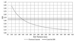
Figure 8 shows the variation of SSR (ratio of actual applied flexural stress to flexural strength) for both pervious and conventional concrete under 80-kN axle loading versus slab thickness. Figure 9 shows the variation of SSR for the 22-kN load versus the pervious concrete slab thickness. The Portland Cement Association (PCA) manual for rigid pavement design (PORTLAND…, 1984PORTLAND CEMENT ASSOCIATION. Thickness design for concrete highways and street pavements. EB 109.01P, Skokie, 1984.) for conventional concrete suggests a maximum value of SSR of 0.45 in order to avoid fatigue degradation under successive loads cycles, which means that the pavement can be subjected to unlimited cycles if SSR is under 0.45, which however is not clear and do not belong to a common sense yet. As the pervious concrete technology is recent, field-calibrated fatigue transfer functions have not been developed to be used as a reference for structural analysis of this kind of pavement. Therefore, still the PCA assumption was used to provide a comparison between conventional and pervious concrete designs.
It can be observed in Figure 8 for the 80 kN-axle that, while for conventional concrete the slab thickness must be higher than 190 mm in order to keep SSR lower than 0.45, for the pervious concrete, this minimum thickness is 300 mm, which is considerably higher than regular thicknesses used for plain conventional concrete slabs. However, pervious concrete slabs with thickness ranging from 200 mm to 300 mm have been used for pavement placements in USA (OBLA, 2007OBLA, K. H. Pervious Concrete for Sustainable Development. Recent Advances in Concrete Technology, Washington D.C., 2007. Available at: Available at: https://www.nrmca.org/research/Pervious%20recent%20advances%20in%20concrete%20technology0707.pdf . Access: 15 nov. 2020.
https://www.nrmca.org/research/Pervious%...
) and it has been reported that some of those pavement structures performed well during several years under heavy-vehicles traffic [23]. It can also be observed that for thicknesses of 110 mm and 170 mm, for conventional and pervious concrete, respectively, the slab’s rupture occurs after one single loading cycle of the 80-kN load, since the SSR equals to the unit.
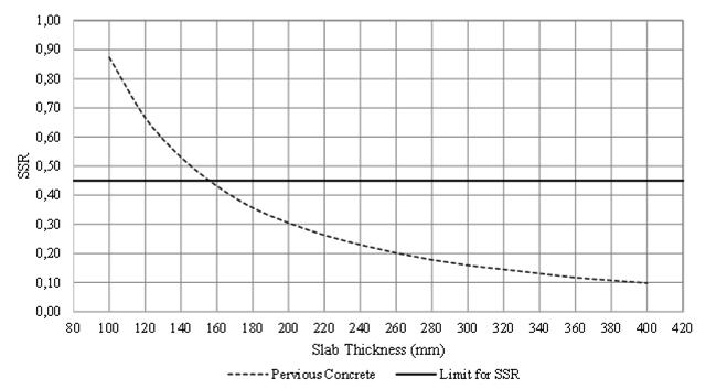
For the 22-kN two-wheels axel load, as it can be seen in Figure 9, a thickness higher than 160 mm can assign a SSR value lower than 0.45 for the structure, suggesting that for light-traffic areas (as parking lots and public squares) the pervious concrete with porosity of 25% and appropriate slab thickness could be used according to PCA assumptions for design. Despite the PCA design hypothesis cannot be directly applied for structural analysis of pervious concrete, since its behavior may be completely different of traditional concrete behavior in terms of fatigue performance, the comparison is sound if one considers that, due to high contents of voids, fatigue behavior of pervious concrete shall be poorer, what sets the thickness results as minimum for comparison aims. According to recent studies on fracture and fatigue of pervious concrete, its behavior under cyclic loading is worse than conventional concrete behavior (CHEN et al., 2013CHEN, Y. et al. Strength, fracture and fatigue of pervious concrete. Construction and Building Materials, v. 42, p. 97-104, 2013.), as a matter of fact, strengthening the clue that the thickness required for heavy traffic design is more likely higher than 300 mm.
Figure 10 shows the results of admissible number of load repetitions calculated by using StreetPave fatigue model for a range of slab thicknesses for both pervious and conventional concretes, considering loading conditions of 80 kN and 22 kN. The ACPA has recently released the PerviousPave, software that can be used for hydraulic and mechanical design of pervious concrete pavements (RODDEN; VOIGT; GIERALTOWSKI, 2010RODDEN, R.; VOIGT, G.; GIERALTOWSKI, A. Pervious Pave (Software). Skokie: American Concrete Paving Association, 2010.; CARGNIN et al., 2015CARGNIN, A. P. et al. Sensitivity analysis of the thickness in porous concrete pavements design for Bus Rapid Transit (BRT) Busways. In: INTERNATIONAL CONFERENCE ON BEST PRACTICES FOR CONCRETE PAVEMENTS, 3. Bonito, 2015. Proceedings… Bonito: Brazilian Concrete Institute, 2015.). Despite this software was created specifically for solving pervious concrete pavement problems, the fatigue model used is still the same as the one used in StreetPave software. A full-scale fatigue test of pervious concrete pavement is recommended so any fatigue analysis can be calibrated with data that reflects field pervious concrete pavement behavior rather than conventional concrete pavement behavior.
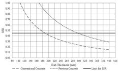
Variation of SSR versus slab thickness for conventional and pervious concrete for the 80-kN four-wheel axle load
Variation of SSR versus slab thickness for pervious concrete for the 22-kN two-wheel axle load

Loads of 80 and 22 kN refers, respectively, to truck rear axles and to passengers’ cars axles. For low volume parking areas and public parks, the expectation for repetition of truck axles are low, even 1,000,000 in ten years, alike low volume roads. For a plastic conventional plain concrete (about 5 MPa flexural strength) thicknesses in excess of 150 mm to 160 mm are required for the design period; in the case of pervious concrete the thickness of the coating concrete slabs shall be too much higher, as 240 mm. Such a requirement can’t be seen as costly nor environmentally appropriate, since unitary costs for pervious concrete are similar or higher than conventional concretes. In view of such achievements from this study it is hard to, currently, expand the use of pervious pavements for any kind of road, keeping it fully applicable to cars parking lots at shopping c enters and commercial areas as well for sidewalks for general use and bikeways within the urban environment.
Conclusions
It was presented an investigation on the mechanical and hydraulic properties of three different mixes of pervious concrete cast in laboratory supplemented by a field application study on a sidewalk. The results were then used to perform a mechanistic analysis to figure out the suitability of pervious concrete to be used as the surface layer of permeable pavements under loads other than automobiles. The major findings were:
-
the coarse aggregate gradations used for this study do not appear to have significant effects on the results of all tests performed, since the values were very similar for all three pervious concrete mixes. This fact can be explained by the low variation of the porosities, which ranged from 23% to 26%;
-
destructive tests (strength measurements) of pervious concretes resulted in more scattered results than those generally obtained for conventional concretes in laboratory. The high variability might be related to the high porosity and porosity variability of pervious concrete, which tends to increase the variability of destructive tests in the laboratory;
-
both the flexural strength and the static modulus of elasticity of the pervious concrete with 25% of porosity was on average 2.1 MPa and 16 GPa, respectively, which is about 50% lower than the same properties for conventional pavement concrete; however, the ratio between modulus of elasticity and flexural strength is preserved for the pervious concrete in reference to conventional concretes for paving;
-
the ratio between the elastic modulus (static/dynamic) obtained in this study was on average 70% which is slightly less than common ratios observed for conventional and high strength concretes, ranging from 75% to 83%;
-
in the present study the coefficient of variation of the results for both porosity and hydraulic conductivity tests in the laboratory were small, ranging from 1.5% to 11%. In addition, the results from the constant head test were less scattered than those obtained in the falling head test;
-
the differences between the average results of hydraulic conductivity, where the falling head permeability was always higher than the constant head permeability, may be associated with the lateral confinement of the specimens. The lateral confinement may not have fully covered the specimens in the falling head tests due the limitations of the apparatus;
-
the surface infiltration rates just after construction in the field were similar to the laboratory tests using falling head tests for mixture M1, and therefore, even these differently compacted specimens may provide reasonable results for predicting the field hydraulic behavior of pervious concrete;
-
dense areas of vegetation can contribute to early clogging of pervious concrete surface what requires more maintenance activities during the lifespan of such pavement structure since, permeability is a performance demand for any pervious pavement;
-
the results of surface infiltration rate in the field varied from 0.10 to 1.06 cm/s (28 days after construction of the sidewalk) and were reduced to 0.04 cm/s to 0.55 cm/s after approximately four months of sidewalk exposure. The higher loss of permeability was 92% in approximately four months, and it is attributed to the clogging of the structure due to the infiltration of dirt particles and organic matter from decaying leaves which fell from nearby trees during the rainy summer and the beginning of the fall season;
-
infiltration rates observed mostly fully comply, in any time of the presented measurements, the minimum requirements (0.1 cm/s) suggested by NBR16416 (ABNT, 2015), what permits to state that the pavement submitted to the clogging process in a dense wooded tropical (even exotic) garden, after two years, still works well in terms of capabilities of collecting superficial storm water;
-
the modulus of elasticity obtained from the FWD basins backcalculations resulted 17 GPa and 24 GPa, which is close to but higher than the average of 16 GPa obtained for the prismatic specimens in the laboratory (static test) for mixture M1. This difference is more likely associated with the type of load application (dynamic versus static) and the low bearing capacity of the uncompact base and subgrade layers (verified through the very low k-values for the supporting system), which tends to increase the dynamic response of the concrete layer due to the dynamic load;
-
mechanistic analysis shows that for the 80-kN four-wheel truck or bus axle loading, the pervious concrete slab thickness is required to be a minimum of 300 mm, considering the PCA fatigue design procedure. This thickness is the maximum value commonly reported for pervious concrete placements in US for heavy traffic, since higher thickness could result in the concrete self-compaction, which may seal the slab bottom. It was also verified that, for light-traffic vehicles with a 22-kN two-wheel axle loading, a thickness of 160 mm could be enough for the pervious concrete slab to keep SSR below 0.45; and
-
the requirement of thickness pointed out by NBR 16416 (ABNT, 2015) of 100 mm for light traffic is questionable and possibly mistaken under the mechanistic analysis carried out in this study. As shown, 200 mm of pervious concrete is required to allow a number of repetitions of light vehicles of little more than 1,000, placing an important modification on this concept of minimum thickness because failed as currently applied.
It must be stressed that the fatigue behavior for pervious concrete is probably more critical than for conventional concrete due its porous structure, which will lead to greater slab thicknesses for pavements applications. Fatigue and its relation to porosity on pervious concrete can be the key for designing pervious pavements as well as the pervious concrete proportioning technique.
Acknowledgments
Authors acknowledge to CNPq (Ministry of Science and Technology of Brazil), CAPES (Ministry of Education of Brazil), the São Paulo Foundation for Research (FAPESP) for grants for individual research (CNPq - Universal 2014), scholarship for PhD and MSc programs (CAPES) as well for undergraduate scholarships for undergraduate research (CNPq and FAPESP). Also are grateful to Lafarge-Holcim Brazil for support on field application of fresh concrete (supplying raw material), to Odebrecht Environment Company for supplying the recycled aggregates for pavement bases and to Mr. Claudio Freitas and its construction company for site construction (EP - Floors Engineering). USP campus prefecture in Sao Paulo has supported construction logistics and infiltration tests through Mr. Douglas Costa.
References
- AMERICAN SOCIETY FOR TESTING AND MATERIALS. C1701/C1701M: standard test method for infiltration rate of in place pervious concrete. West Conshohocken, 2009.
- AMERICAN SOCIETY FOR TESTING AND MATERIALS. C1754/C1754M: standard test method for density and void content of hardened pervious concrete. West Conshohocken, 2012a.
- AMERICAN SOCIETY FOR TESTING AND MATERIALS. C39/C39M: standard test method for compressive strength of cylindrical concrete specimens. West Conshohocken, 2016a.
- AMERICAN SOCIETY FOR TESTING AND MATERIALS. C496/C496M: standard test method for splitting tensile strength of cylindrical concrete specimens. West Conshohocken, 2011.
- AMERICAN SOCIETY FOR TESTING AND MATERIALS. C580-02: standard test method for flexural strength and modulus of elasticity of chemical-resistant mortars, grouts, monolithic surfacings, and polymer concretes. West Conshohocken, 2012b.
- AMERICAN SOCIETY FOR TESTING AND MATERIALS. C597-16: standard test method for pulse velocity through concrete. West Conshohocken, 2016c.
- AMERICAN SOCIETY FOR TESTING AND MATERIALS. C78/C78M: standard test method for flexural strength of concrete (using simple beam with third-point loading). West Conshohocken, 2016b.
- AMERICAN SOCIETY FOR TESTING AND MATERIALS. D2434-68: standard test method for permeability of granular soils (Constant Head). West Conshohocken, 2006.
- AMERICAN SOCIETY FOR TESTING AND MATERIALS. D5858: standard guide for calculating in situ equivalent elastic moduli of pavement materials using layered elastic theory. West Conshohocken, 2015a.
- AMERICAN SOCIETY OF CIVIL ENGINEERS. Permeable Pavements. Permeable Pavement Task Committee, 2015.
- ASSOCIAÇÃO BRASILEIRA DE NORMAS TÉCNICAS. NBR 16416: revestimentos permeáveis de concreto: requisitos e procedimentos. Rio de Janeiro, 2015.
- ASSOCIAÇÃO BRASILEIRA DE NORMAS TÉCNICAS. NBR 16697: cimento Portland: requisitos. Rio de Janeiro, 2018.
- BATEZINI, R.; BALBO, J. T. Estudo da condutividade hidráulica com carga constante e variável em concretos permeáveis. Revista IBRACON de Estruturas e Materiais,v. 8, n. 3, p.248-259, 2015.
- BEELDENS, A. Behaviour of porous PCC under freeze thaw cycling. In: INTERNATIONAL CONGRESS ON POLYMERS IN CONCRETE, 10.,Honolulu, 2001. Proceedings… Honolulu, 2001.
- BEELDENS, A.; VAN GEMERT, D.; CAESTECKER, C. Porous concrete: laboratory versus field experience. In: INTERNATIONAL SYMPOSIUM ON CONCRETE ROADS, 9., Istanbul, 2003. Proceedings… Istanbul, 2003.
- BOOTH, D.B.; HARTLEY, D.; JACKSON, R. Forest cover, impervious-surface area, and the mitigation of stormwater impacts. Journal of the American Water Resources Association, v. 38, n. 3, p. 835-845, 2002.
- CARGNIN, A. P. et al Sensitivity analysis of the thickness in porous concrete pavements design for Bus Rapid Transit (BRT) Busways. In: INTERNATIONAL CONFERENCE ON BEST PRACTICES FOR CONCRETE PAVEMENTS, 3. Bonito, 2015. Proceedings… Bonito: Brazilian Concrete Institute, 2015.
- CHEN, Y. et al Strength, fracture and fatigue of pervious concrete. Construction and Building Materials, v. 42, p. 97-104, 2013.
- DAVIDS, W.G. et al Three-dimensional finite element analysis of jointed plain concrete pavement with EverFE 2.2. Transportation Research Record: Journal of the Transportation Research Board, TRR 1853, p. 92-99, 2003.
- DELATTE, N.; MRKAJIC, A.;MILLER, D.I. Field and laboratory evaluation of pervious concrete pavements. Transportation Research Record: Journal of the Transportation Research Board , v. 2113, n. 1, 2009.
- DIETZ, M. E. Low impact development practices: a review of current research and recommendations for future directions. Water, Air, and Soil Pollution, v. 186, n. 1, p. 351-363, 2007.
- GOEDE, W.G. Pervious concrete: investigation into structural performance and evaluation of the applicability of existing thickness design methods. Thesis (MSc), Washington State University, Pullman, 2009.
- HASELBACH, L.; FREEMAN, R. Vertical porosity distributions in pervious concrete pavement. ACI Materials Journal, v. 103, n. 6, p. 452-458, 2006.
- HENDERSON, V.; TIGHE, S.L.; NORRIS, J. Pervious concrete pavement: integrated laboratory and field study. Transportation Research Record: Journal of the Transportation Research Board , v. 2113, n. 1, 2009.
- HOLCIM BRAZIL. Relatório de Caracterização do Cimento pelo Fabricante. 2010.
- HUANG, B. et al Laboratory evaluation of permeability and strength of polymer-modified pervious concrete. Construction and Building Materials , v. 24, p. 818-823, 2010.
- HUNT, W. F.; COLLINS, K. A. Permeable pavement: research update and design implications. Special Report, Department of Biological and Agricultural Engineering, North Carolina State University, 2008.
- IOANNIDES, A. M. Extension of Westergaard solutions using dimensional analysis. In: INTERNATIONAL WORKSHOP ON THE THEORETICAL DESIGN OF CONCRETE PAVEMENTS, 2., Siguenza, 1990. Proceedings… Siguenza, 1990.
- KAJIO, S. et al Properties of porous concrete with high strength. In: INTERNATIONAL SYMPOSIUM ON CONCRETE ROADS, 8., Lisbon, 1998. Proceedings… Lisbon, 1998.
- KHAZANOVICH, L. Dynamic analysis of FWD test results for rigid pavements. Nondestructive Testing of Pavements and Backcalculation of Moduli Third Volume, American Society for Testing and Materials, ASTM STP1375:, West Conshohocken, 2000.
- LEE, M. G. et al Experimental study of pervious concrete on parking lot. Proceedings of the GeoHunan International Conference, v. 193, n. 20, p. 125-131, 2009.
- LUND, M.; KEVERN, J. V.; SCHAEFER, K. H. Mix Design for improved strength and freeze-thaw durability of pervious concrete fill in pearl-chain bridges. Materials and Structures, v. 50, n. 42, 2017.
- MCCAIN, G. N.; DEWOOLKAR, M. M. Porousconcrete pavements. Transportation Research Record: Journal of the Transportation Research Board , TRR 2164, p.66-75, 2010.
- MONTES, F.; HASELBACH, L. Measuring hydraulic conductivity in pervious concrete. Environmental Engineering Science, v. 23, p.960-969, 2006.
- MONTES, F.; VALAVALA, S.; HASELBACH, L. M. A new test method for porosity measurements of Portland cement pervious concrete. Journal of ASTM International, v. 2, n. 1, 2005.
- NEVILLE, A. M. Properties of Concrete. 4thed. New York: John Wiley & Sons Inc., 1997.
- OBLA, K. H. Pervious Concrete for Sustainable Development. Recent Advances in Concrete Technology, Washington D.C., 2007. Available at: Available at: https://www.nrmca.org/research/Pervious%20recent%20advances%20in%20concrete%20technology0707.pdf Access: 15 nov. 2020.
» https://www.nrmca.org/research/Pervious%20recent%20advances%20in%20concrete%20technology0707.pdf - OLEK, J. et al Development of quiet and durable porous Portland cement concrete paving materials. Final Report SQDH-5 Center of Advanced Cement Based Materials, Purdue, 2003.
- PARK, S. B.; TIA, M. An experimental study on the water-purification properties of porous concrete. Cement and Concrete Research, v. 34, p. 177-184, 2004.
- PINDADO, M. Á.; AGUADO, A.; JOSA, A. Fatigue behavior of polymer-modified porous concretes. Cement and Concrete Research , v. 29, p. 1077-1083, 1999.
- POPOVICS, J.S.; ZEMAJTIS, J.; SHLOLNIK, I. A study of static and dynamic modulus of elasticity of concrete. ACI-CRC Final Report, University of Illinois, Urbana, 2008.
- PORTLAND CEMENT ASSOCIATION. Thickness design for concrete highways and street pavements. EB 109.01P, Skokie, 1984.
- PREFEITURA DO MUNICÍPIO DE SÃO PAULO. Lei Nº 16.402. Diário Oficial do Município de São Paulo, 22 de março de 2016.
- RODDEN, R.; VOIGT, G.; GIERALTOWSKI, A. Pervious Pave (Software). Skokie: American Concrete Paving Association, 2010.
- SCHAEFER, V. R. et al Construction and performance of pervious concrete overlay at minnesota road research project. Transportation Research Record: Journal of Transportation Research Board, TRR 2164, p. 82-88, 2010.
- SCHAEFER, V. R. et al Mix design development for pervious concrete in cold climates. Ames: Iowa State University, 2006. Final Report.
- SHKOLNIK, I. E. Effect of nonlinear response of concrete on its elastic modulus and strength. Cement and Concrete Composities, v. 27, n. 7/8, p.747-757, 2005.
- TAMAI, M.; YOSHIDA, M. Durability of porous concrete. In: CANMET/ACI INTERNATIONAL CONFERENCE ON DURABILITY OF CONCRETE, 6., Thessaloniki, 2003. Proceedings… Thessaloniki: AmericanConcrete Institute, 2003.
- TENNIS, P.vD.; LEMING, M.vL.; AKERS, D. J. Pervious concrete pavements. Skokie: Portland Cement Association, 2004. EB302.
- TITUS-GLOVER, L. et al Enhanced portland cement concrete fatigue model for Street Pave. Transportation Research Record: Journal of the Transportation Research Board , TRR 1919, p. 29-37, 2005.
- VANCURA, M.; MACDONALD, K.; KHAZANOVICH, L. Structural analysis of pervious concrete pavements. Transportation Research Record: Journal of the Transportation Research Board , TRR 2226, p.13-20, 2011.
- ZAHARIEVA, R. et al Assessment of the surface permeation properties of recycled aggregate. Concrete Cement and Concrete Composites, v. 25, n. 2, p. 223-232, 2003.
- ZHANG, Z. et al Influence of crushing index on proprieties of recycled aggregates pervious concrete. Construction and Building Materials , v. 135, p. 112-118, 2017.
Publication Dates
-
Publication in this collection
05 Mar 2021 -
Date of issue
Apr-Jun 2021
History
-
Received
01 Jan 2020 -
Accepted
13 July 2020