 Finite Element Analysis of a Novel Implant Designed for Soft Tissue Protection in Proximal Ulna Fracture Fixation: An In Silico Comparative Study
Abstract
Osteosynthesis of multifragmentary proximal ulna (PU) fractures often requires a second surgery to remove the implant due to discomfort. This in silico study presents a novel implant, the Y-plate, aimed at improving soft tissue protection, reducing costs, and simplifying the surgical procedure. The methodology involved the creation of 3D digital models of the PU along with four plate and screw fixation systems (LCP, Synthes®, A+B, and the Y-plate). This was followed by a stability comparison between the systems through simulations using the finite element method (FEM). Relative displacements were evaluated under maximum loads at different elbow flexion angles (0°, 45°, and 90°), applying forces of 50 N, 100 N, and 500 N. As a result, all systems showed satisfactory stability, with displacements below 2 mm with the A+B plate fixation demonstrating the greatest displacement under the maximum load of 500 N in all positions. We concluded that the Y-plate represents a promising proof of concept, combining the advantages of lateral and posterior fixations in a single implant, better soft tissue protection, and potential cost reductions. Despite the limitations of the in silico study, our findings provide a robust basis for developing a physical prototype. This will be used in future in vitro and clinical validations, aiming to improve the treatment of multifragmentary PU fractures.
Keywords:
Ulna; Elbow Fractures; Finite Element Analysis; Prostheses and Implants.
HIGHLIGHTS
Introduces a novel Y-plate implant for proximal ulna fracture fixation.
Aims to reduce reoperations by enhancing soft tissue protection.
Finite Element Analysis confirms Y-plate's stability, comparable to current systems.
Promises cost reduction and surgical simplification for improved patient care.
INTRODUCTION
Ulna fractures in adults involving the proximal forearm region account for approximately 20% of arm bone fractures [1]. They are considered complex injuries, as most involve fragments displaced from the articular surface, making correct treatment fundamental to prevent sequelae such as joint stiffness, instability, chronic pain, and arthrosis, among others. Treatments include anatomical joint reconstruction and stable osteosynthesis in order to quickly regain joint mobilization. In multifragmentary fractures (MFF), these treatments are more challenging, depending on bone quality, size and/or number of fragments, and the types of implants available [2]. Among existing implants, the most commonly used are plates fixed with metal screws or tension band wiring with steel wires. The latter has shown efficiency over the years, but its use is restricted to simple trace fractures. For MFF, the most commonly used and highly recommended implants are plates and screws [3]. In both techniques, implant adaptation is performed on the posterior aspect of the proximal ulna (PU), which has little soft tissue coverage, potentially causing local discomfort due to the friction caused by the metals rubbing against the soft tissues. For this reason, a second procedure to remove the implant is common, with incidences ranging between 15% and 56% [4]. This high rate of surgical reintervention represents a significant burden for patients and healthcare systems, highlighting the need for innovative solutions. The inadequate design of older plates (straight, non-anatomical, thicker profile, and larger diameter screws) has led to a rethink of their modeling as well as improving their placement within patients. Recent modifications have been proposed, such as anatomically shaped, thinner plates, demonstrating stability comparable to older ones, but these plates still often require removal after the injury has healed [5]. Using plates on the lateral and medial aspects of the PU has been presented as a good alternative, mitigating this complication and maintaining biomechanical efficiency, but this requires two implants and a greater number of screws, significantly increasing costs. Therefore, a method that provides good stability without causing soft tissue friction and at an affordable cost is still desired and the subject of several recent studies [6-8]. The objective of this study is to present a novel implant and compare its stability with the three models already used currently. The new design was evaluated in silico by the finite element method (FEM) as an initial study to judge its feasibility before more complex in vitro and clinical trials.
MATERIAL AND METHODS
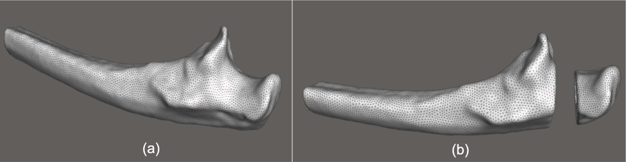
The methodology accepted by the Research Ethics Committee (CAAE: 82249924.3.0000.5218, Decision: 7.069.183) followed three stages. Initially, two bone models of the PU were created in a three-dimensional (3D) digital file: one of a normal bone and another simulating an MFF. This process used original images from a computed tomography (CT) scan of a normal adult left elbow without signs of osteoporosis as a DICOM file, containing 257 images (weighted for soft tissues) with a thickness of 1.25 mm each. Images were obtained with a General Electric Healthcare™ (USA) 128-Resolution CT scanner, 120 Kv, up to 440 mA. Segmentation and 3D reconstruction were obtained using the InVesalius® software (version 3.1.1, Brazil), with cleaning and defect correction done using the Autodesk® Meshmixer™ software (version 3.3.15, USA), without altering the original bone scale and format. From the normal PU, the ulna with an MFF was created by removing 10 mm of bone in the articular region, starting at 5 mm proximal to the coronoid process, with the two bone fragments maintaining contact, as shown in Figure 1.
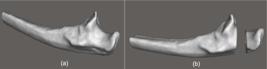
Images showing the proximal ulna models created using Autodesk® MeshmixerTM software (version 3.3.15). In (a): intact bone; (b): bone with simulated bone defect corresponding to a multifragmentary fracture. Source: the authors
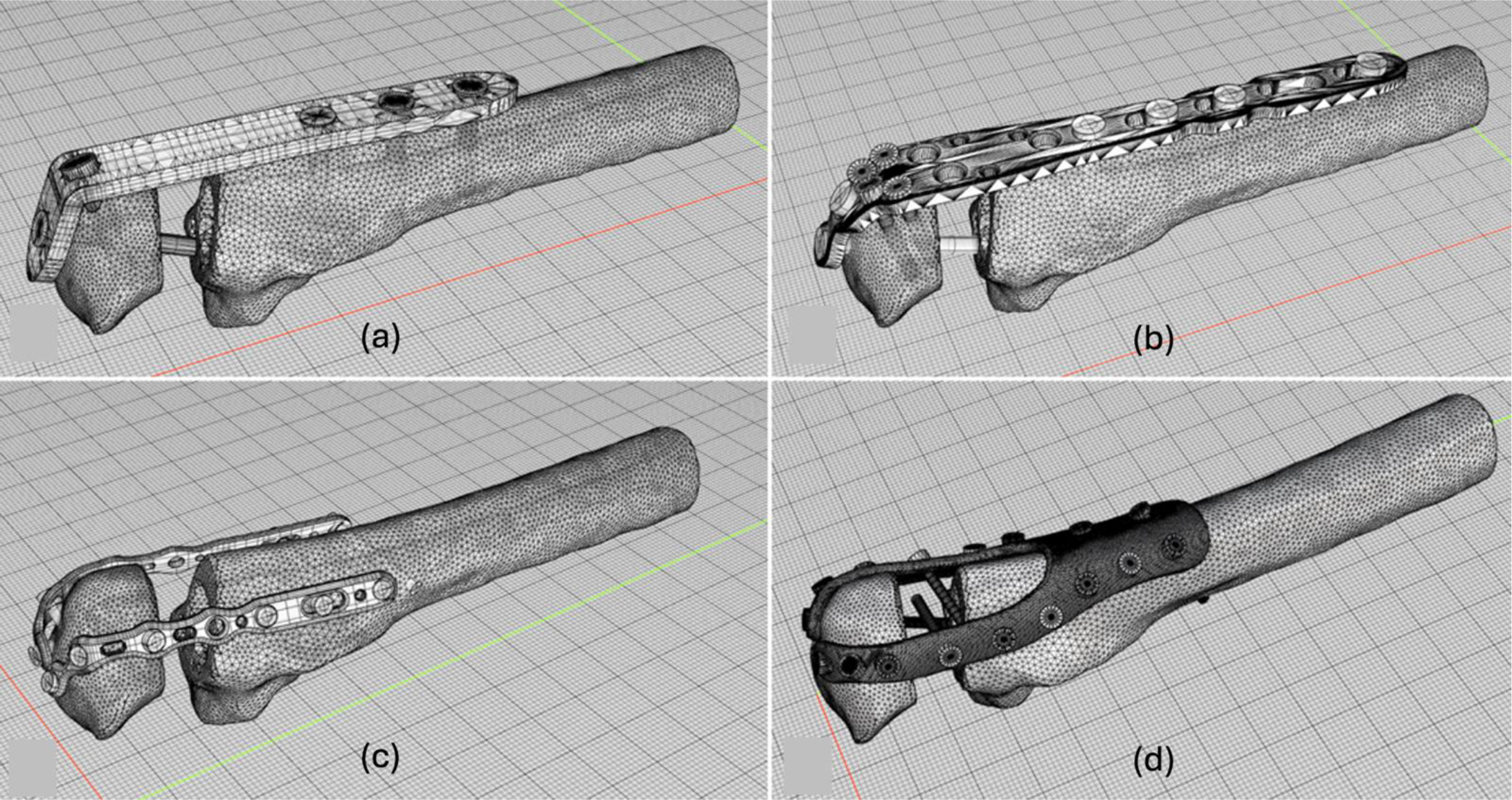
The second stage involved computational models of plate and screw fixation designed using the Rhinoceros® CAD software (version 5.5.2, 5F85, licensed), maintaining the original format and scale. Three were based on physical models of plates already used in medical practice: a straight locking compression plate (LCP) 3.5 mm thick with six threaded locking holes (LCP™ System, DePuySynthes®); a 3.5 mm anatomical locking plate with four distal holes (LCP™ System, DePuySynthes®); two plates 1.6 mm thick for medial and lateral fixation, with seven holes and a locking system (Aptus Elbow, Medartis®, Switzerland); and three types of screws (2.0 mm, 2.8 mm, and 3.5 mm in diameter), with varied lengths according to the plate model used and the application site. The new plate proposed, referred to as the Y-plate throughout the study, had a thickness of 2.0 mm with 2.0 mm holes for fixation with 2.0 mm non-locking screws. The fixations were modeled with their respective implants, creating four systems: LCP, Synthes®, A+B, and Y, as shown in Figure 2.
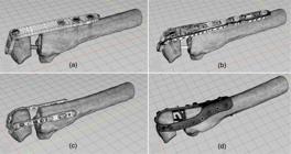
Images showing the final assembly of the 4 fixation systems created in STL format using Rhinoceros® software (version 5.5.2, 5F85). In (a): LCP; (b): Synthes®; (c): A+B; (d): Y. Source: the authors
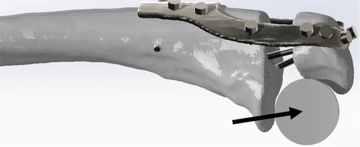
At the third and final stage, the stability of the above systems was tested using FEM simulations. All solid models (fractured bone and implants) underwent a process of simplification and the creation of finite element meshes, reducing the number of faces. The solid bodies were made using the Autodesk® Meshmixer™ and SolidWorks® software (version Premium 2022 SP0.0, USA). Based on previous studies, a cylinder of 20 mm in diameter by 20 mm in length was modeled in SolidWorks® and positioned in the articular region of the PU to simulate contact with the humeral condyle, as shown in Figure 3 [9-11].
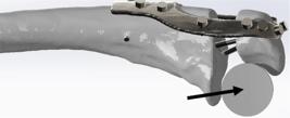
Image showing the final assembly of the Y plate system after the creation of the cylinder (arrow) to simulate the distal humerus, using SolidWorks® software (Premium version 2022 SP0.0). Source: the authors
The CAE program Ansys® (USA, version 2023 R1 23.1, licensed) was used for structural simulation using FEM, following these steps:
- Ansys® Workbench Interface: selection of the type of static structural simulation to evaluate the relative bone displacement in relation to the maximum possible efforts in a critical situation.
- Definition of the mechanical properties of the materials: the implants were defined as cold-rolled AISI 316 steel and the bone as cortical and isotropic, with linear elastic and homogeneous properties. The mechanical properties of cortical bone and metal are shown in Tables 1 and 2 [12-14].
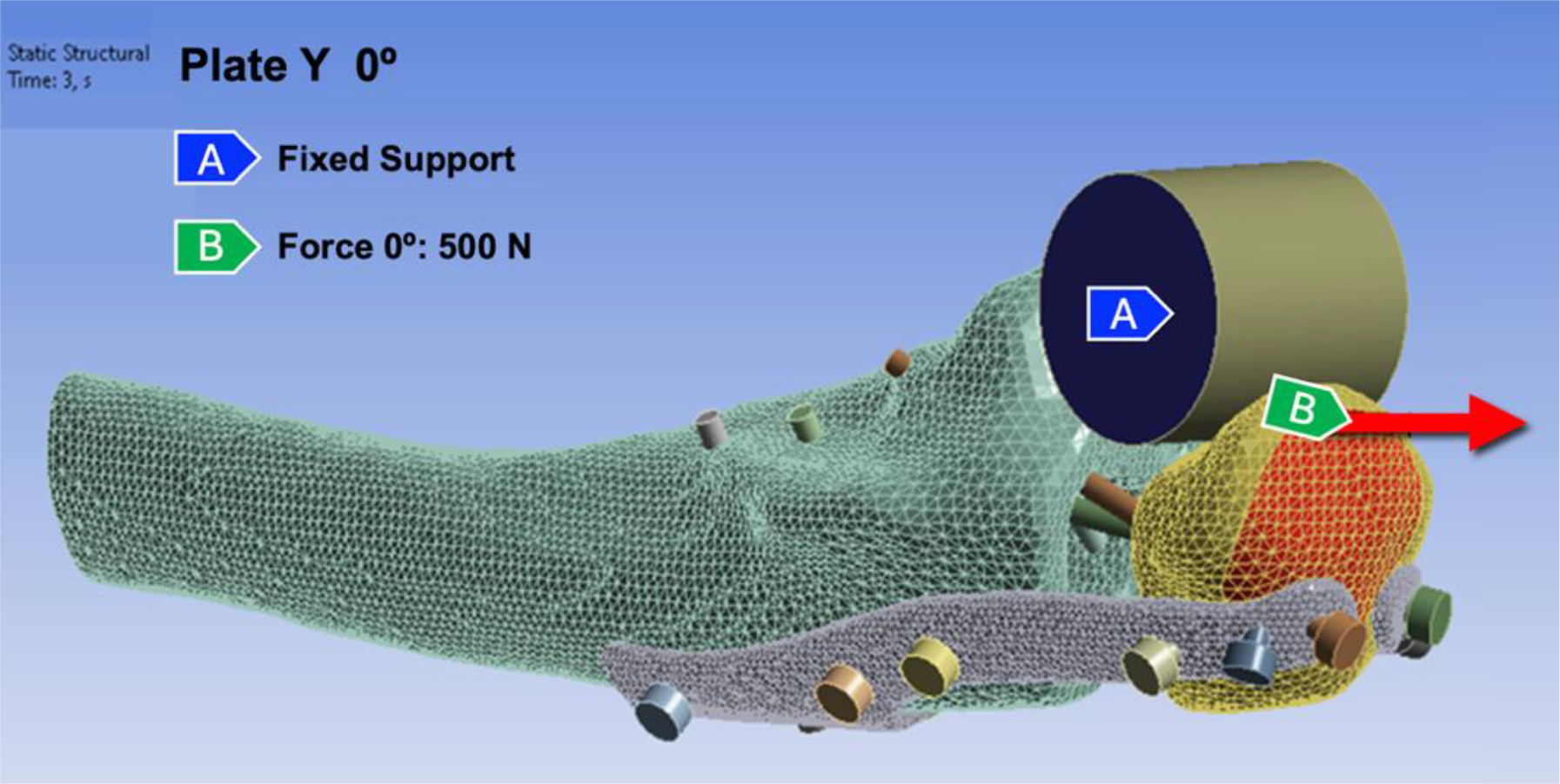
- Boundary conditions and contacts: real-world scenarios were created by defining the area for force application by the triceps brachii muscle tendon on the PU. The contacts between the surfaces were defined as fixed (bonded) between screws, plate, and bone. For non-locked screws (only in the Y-plate), the bonded definition was only applied in the thread region, defining the frictional contact between screws and plate. A friction coefficient of 0.46 was used for plate-bone contacts and 0.37 for bone-bone contacts [13,14]. The distal end of the ulna and the distal humerus cylinder were defined as fixation points. For load application, three modules were evaluated in three different directions (0°, 45°, and 90° relative to the axial axis of the ulna), corresponding to the same degrees of elbow flexion, with loads of 50 N, 100 N, and 500 N, applied sequentially over time (1, 2, and 3 seconds, respectively). Forces were based on values exerted by the triceps brachii muscle on the elbow during basic daily activities, with the highest risk (500 N) related to the act of standing up from a chair by supporting oneself with the upper limb [15]. Figure 4 illustrates an example of the schematization of force direction analyzed for the Y-plate system at 0° flexion, represented in B (red).
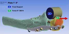
Image showing the application and direction of Force (B, red arrow) on the Y plate system at 0° elbow flexion, in Ansys® software. Source: the authors
- Mesh configurations: for the mesh geometry, a tetrahedral configuration was used, following Wittek and coauthors` recommendations for in silico simulations of irregular elements, ensuring the necessary quality for study precision [16].
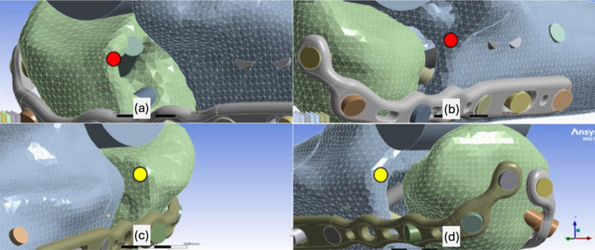
- Collection of relative displacements: to define relative displacements, four pairs of points around the fractured region were selected: A1 and A2 (located on the superior portions of the proximal and distal ends of the medial ulna, respectively); B1 and B2 (located on the superior portions of the proximal and distal ends of the lateral ulna, respectively); C1 and C2 (located on the inferior portions of the proximal and distal ends of the medial ulna, respectively); and D1 and D2 (located on the inferior portions of the proximal and distal ends of the lateral ulna, respectively), as shown in Figure 5.
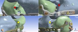
Images in Ansys® software, showing in (a) and (b): points A1 and A2 (red) on the upper portions of the proximal and distal ends of the medial face of the ulna, respectively; in (c) and (d): points B1 and B2 (yellow) on the upper portions of the proximal and distal ends of the lateral face of the ulna, respectively. Source: the authors
Finally, computational simulations were performed. The parameter used to define system failure was a displacement greater than 2 mm between points, as according to the literature [15].
The statistical analysis was performed by Analysis of Variance (ANOVA) with a significance level of p < 0.05. Post-Hoc analysis was performed with Tukey's test to identify which systems had differences among themselves [17,18]. Subsequently, the analysis of von Mises stress distributions was performed to demonstrate failures in the fixation systems as well as show areas of greater stress and overload.
RESULTS
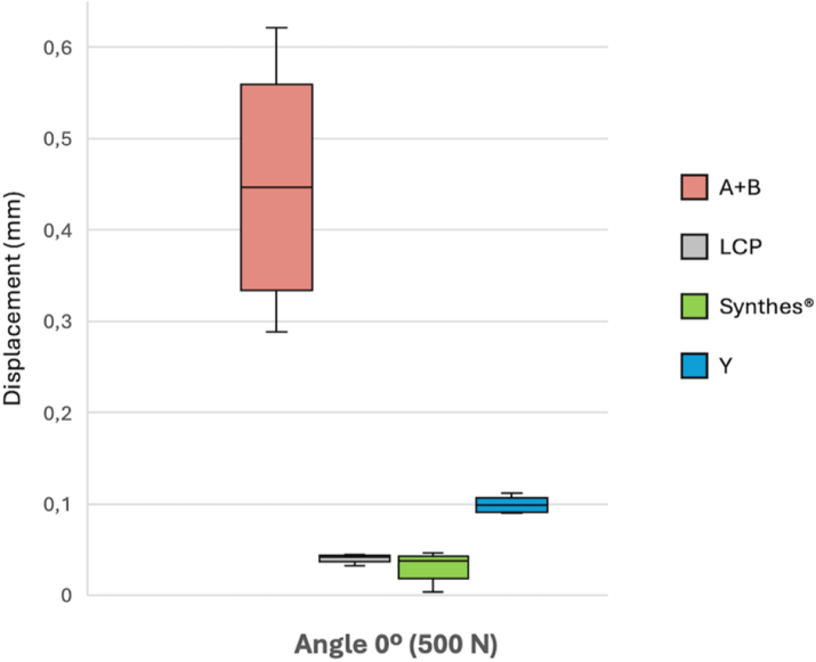
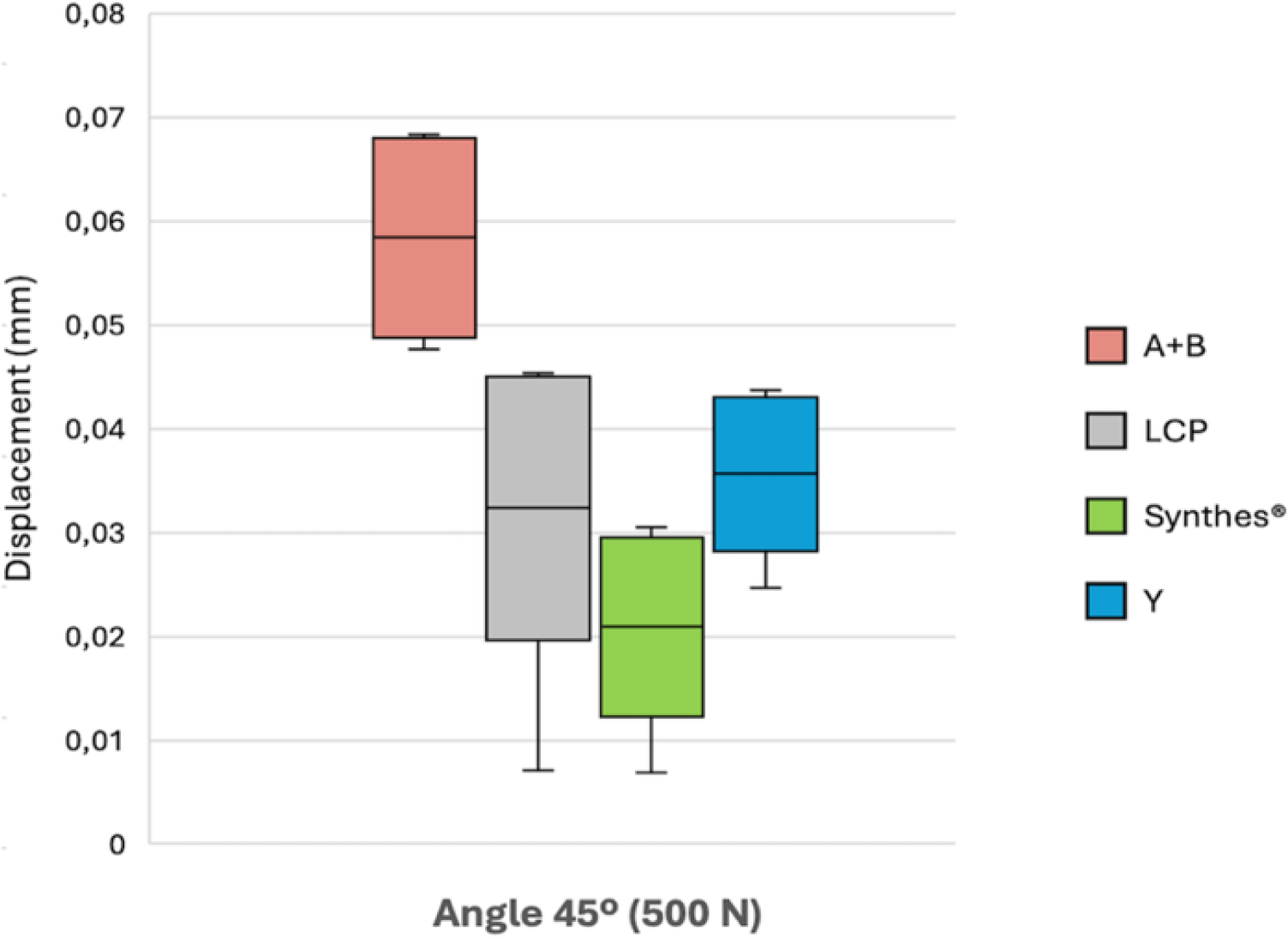
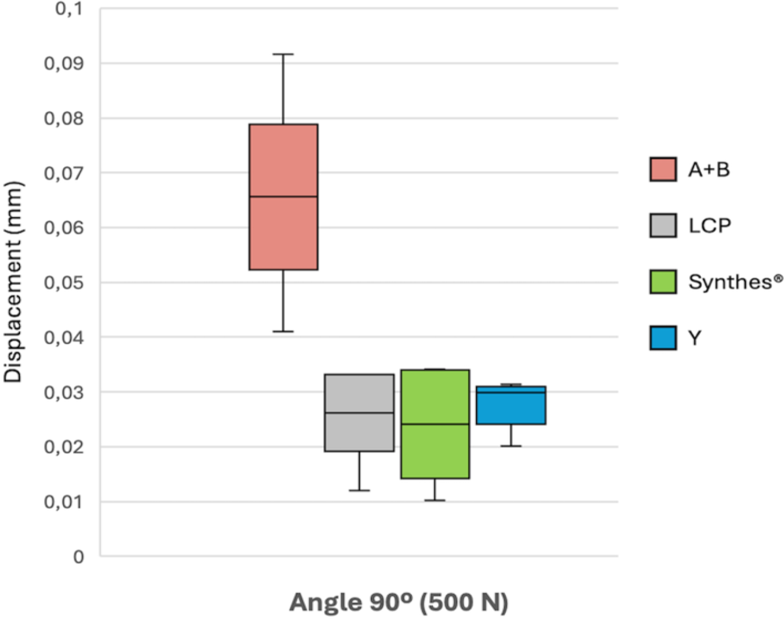
All simulations demonstrated satisfactory stability, with displacements (D) of less than 2 mm. At 45° flexion, the systems showed similar performances, with no statistical difference, at the smallest load of 50 N (p=0.138). At the higher loads of 100 and 500 N, the Synthes® plate demonstrated greater resistance (p=0.009 and p=0.04, respectively). At these loads, the LCP and Y plates had the second-best performance, and the A+B plate the worst. At 90°, all the plates showed equivalent D at loads of 50 N and 100 N (p=0.073 and p=0.044, respectively). However, at 500 N, the A+B plate showed a worse performance (p=0.002). Table 3 presents the mean D of the four systems after applying 50 N, 100 N and 500 N, at 0°, 45°, and 90° of elbow flexion. The A+B plate had a greater D value relative to the others at 500 N at all angles (p=0, 0.009 and 0.002, respectively). The largest D observed with the A+B plate was at 0°, which corresponds to the elbow being fully extended (4.9% on average).
The graphical demonstration of D values in the systems at 0º, 45º and 90º subjected to a force of 500 N are shown in Figures 6, 7 and 8, respectively.
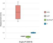
Box-plot graphic showing statistical analysis of displacement differences between fixation systems, with the elbow at 0° of flexion, subjected to load of 500 N. Source: the authors
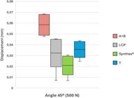
Box-plot graphic showing statistical analysis of displacement differences between fixation systems, with the elbow at 45º of flexion, subjected to load of 500 N. Source: the authors
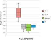
Box-plot graphic showing statistical analysis of displacement differences between fixation systems, with the elbow at 90º of flexion, subjected to load of 500 N. Source: the authors
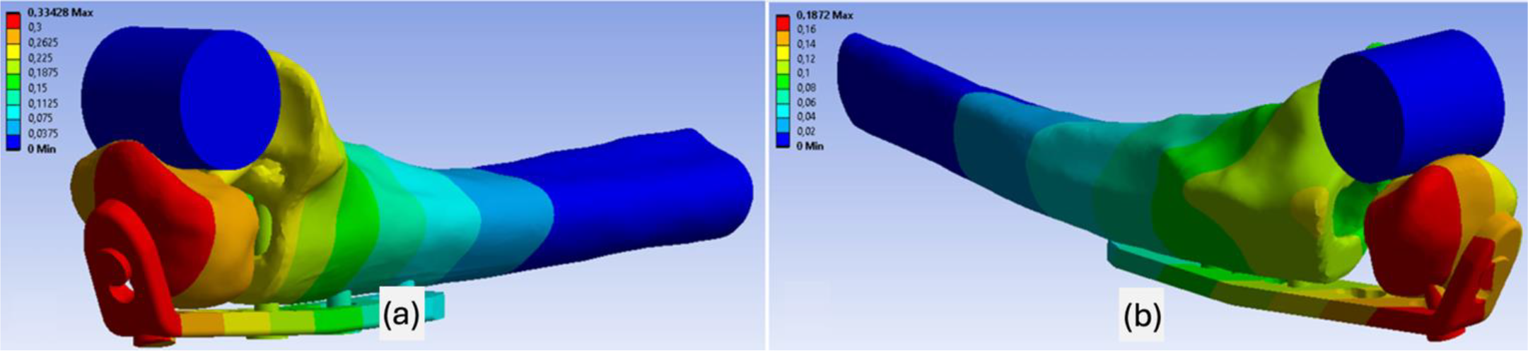
In addition to quantitative evaluation, visual assessment of D showed similar patterns across all models. At 0°, system movement was greater in the posterior region of the PU. At 45° and 90°, the largest D was observed in the lateral portion of the proximal fragment, next to the plate segment. An example with the LCP system is shown in Figure 9.
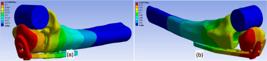
Visual representation of the area of greatest displacement in mm (red) of the LCP-type fixation system (a): 0° flexion, medial vision; (b): 45° flexion, lateral vision. Source: the authors
Regarding the analysis of von Mises stress distributions, the highest stresses were observed in Y and A+B, mainly at 0° (5344 MPa and 3200.5 MPa, respectively), but only in small areas, suggesting localized stress concentrations. All fixation systems demonstrated satisfactory minimum safety coefficients, suggesting a good safety margin before deforming. The maximum von Mises stress values and minimum safety coefficients for each system are shown in Table 4.
Values of maximum von Mises stresses (MPa) and minimum safety factors (Min. Factor) observed in all fixation systems at various flexion positions.
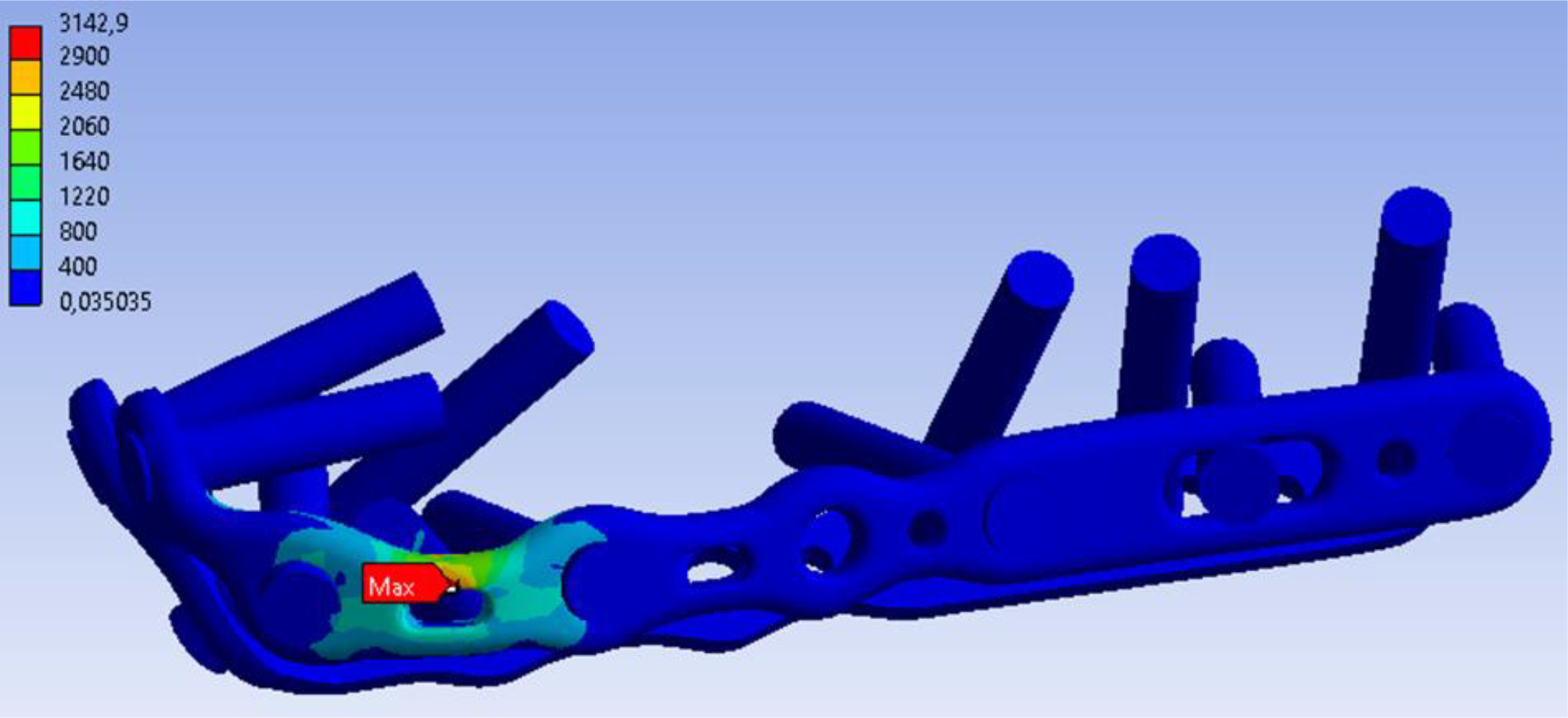
In A+B, stress overload was observed mainly in the proximal portion of the lateral plate, at the transition between the second and third screws, as shown in Figure 10.
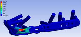
Distribution of von Mises stresses on the A+B plate, with concentration on the proximal lateral portion (between the second and third screws), with the elbow at 90° (red arrow - Max Stress: 3142.9 MPa). Source: the authors
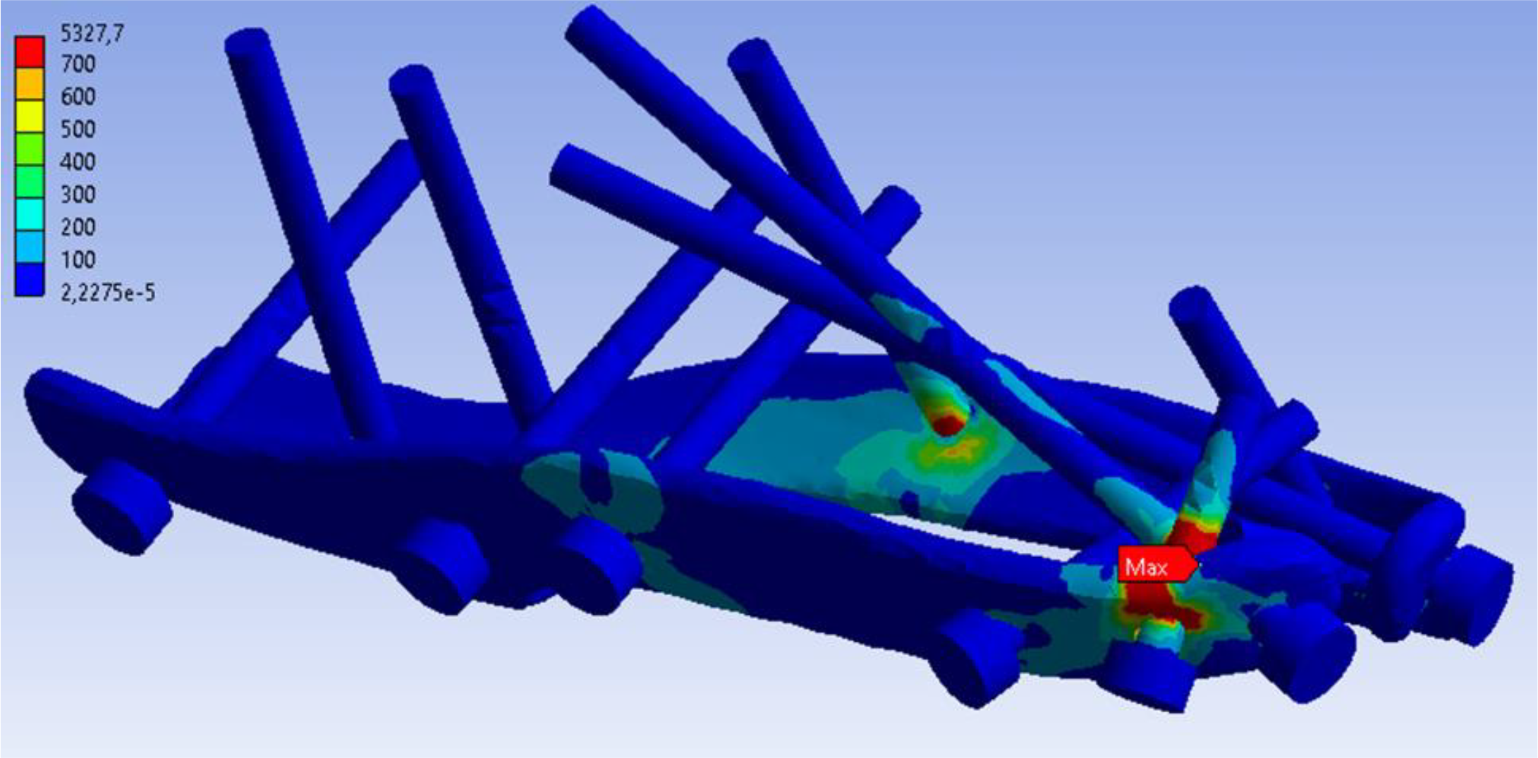
Plates applied to the posterior aspect of the ulna (LCP and Synthes®) had the lowest stress distributions, with the stress transferred to the proximal screws at 0° and 90° positions, especially to the first screw. At 45°, the overload in both systems concentrated on the more distal screws. In Y, stress distribution followed the same behavior at all three positions, concentrating on the posterolateral segment of the implant, similar to the lateral plate of the A+B system, as shown in Figure 11.
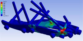
Lateral view of Y system, showing distribution of von Mises stresses, demonstrating overload in the proximal lateral segment (between the second and third screws), with the elbow at 90° (red arrow - Max Stress: 5327.7 MPa). Source: the authors
DISCUSSION
The use of plates for fixation of PU fractures has become increasingly common, especially in cases of MFF, with biomechanical evidence demonstrating a solid, stable, and reliable fixation. For this reason, plate and screw fixation is still considered the gold standard for these types of fractures. Despite this, discomfort caused by friction between the metal implant and soft tissues is still the most common complication and reason for implant removal [4]. King and coauthors suggested using only one plate for better soft tissue protection and reducing discomfort. In that study, straight, 3.5 mm thick plates, originally designed for pelvic fracture fixation, demonstrated a stability equivalent to posterior plates [19]. The proposal of double plating on the lateral aspects of the PU, such as the A+B system here, has shown increased soft tissue protection; however, it is substantially more expensive due to the need for two implants [7]. The central innovation of the Y-plate was focused on combining important concepts: improved soft tissue protection, characteristic of lateral plates, and the proven biomechanical efficiency of posterior plates in a single implant. This combination potentially leads to lower costs and simplifies the surgical procedure. Another design consideration was to ensure that the implant did not interfere with the insertions of the medial and lateral collateral ligaments in the PU. Furthermore, as suggested by Hackl and coauthors, a lower profile plate, as demonstrated by the Y-plate, allows its placement medially under the origin of the flexor carpi ulnaris and the supinator muscles laterally, which provides better plate coverage and less friction with the soft tissues [8].
The results of our FEM trial quantitatively demonstrated the stability efficiency of the new design compared to the other three models. Gordon and coauthors, using double fixation with molded 3.5 mm thick, straight DCP plates, showed that the double plate demonstrated inferior resistance compared to the posterior plate. This was suggested to be due to using thicker plates and screws, with fewer implants in the small proximal ulna fragment. Another reason could be that posterior plates are positioned in the tension area of the fracture, providing greater stability compared to lateral ones [6]. Rochet and coauthors published satisfactory clinical results with the use of two 3.5 mm semi-tubular plates, managing to insert twice as many screws in the proximal fragments and coronoid process [7]. More recent biomechanical studies have confirmed equivalent stability between thinner implants (1.6 mm plate and 2.8 mm screws) and posterior plates [8,10]. The lateral portions of the Y-plate followed these parameters, with a smaller thickness (2 mm) and a greater number of holes. In addition to allowing the insertion of a greater number of screws, 2 holes were created at the metaphysis level to insert screws into the coronoid process, which represents a region of good bone stock. Another possible feature is the insertion of 2 long screws through the most proximal holes, entering through the posterior cortex of the PU to reach the anterior cortex of the coronoid process, uniting the proximal fragment with the distal one. Previous tests have shown that system stability increases with bicortical fixation by placing a greater number of screws in the coronoid or inserting intramedullary screws through the plate [6,20]. This detail may explain the inferior resistance of the A+B system, as the most proximal screws did not reach the coronoid process as in the other systems.
High von Mises stress values were found in small, localized areas of the lateral portion of the plate, between the first and third screws. However, this does not necessarily mean compromising the overall resistance of the implant, as observed in A+B and Y (3200.5 MPa and 5327.7 MPa respectively), but it may suggest high-risk regions at higher loads. Future modifications to address this may include increasing the thickness and width of this region.
Cyclic traction is considered the most faithful model to reproduce the repetitive loads applied during the implant’s lifetime. These loads can generate fatigue and gradual fixation failure in the long term [6,10,15,19-22]. Our test only simulated scenarios with single movements that could put the fixation at risk in the initial postoperative period, representing early catastrophic failures clinically observed within the first two weeks [23]. According to the literature, the maximum load applied to the elbow by the triceps brachii muscle when getting out of a chair is approximately 500 N, and thus determined our maximum force applied [15]. Isometric contraction exercises of the same muscle to prevent muscle atrophy, for example, could be safely initiated in the first days after surgery, as they exert a load of approximately 11.5 N on the elbow [24]. Estimated loads of 150 N (for basic personal care functions close to the body, such as answering the phone, extending the elbow against gravity, or hair combing) could also be exerted with a good safety margin [25-27]. However, depending on the postoperative rehabilitation protocol, especially if cyclic repetitive movements are applied, this situation may vary. Therefore, our study is limited in only considering static forces to the implant. Another limitation of our study refers to the variations in the parameters used in the methodology. To simplify computational calculations, we considered the PU as a normal cortical bone, without osteoporosis, with a higher Young's modulus compared to trabecular bone (16 GPa and 0.55 GPa, respectively), factors that could alter the results [14]. Similarly, the computational model did not consider the actions of the other muscles and ligaments surrounding the elbow joint. The use of bone models without soft tissues is a common practice in most in vitro and in silico biomechanical tests, due to the difficulty of faithfully replicating complex anatomy in laboratory and computational tests. Some authors consider this factor as a methodological advantage, as the prevalence of this approach in the scientific literature establishes a more uniform standard, facilitating comparison and validation of the results between different studies [15]. In most published studies involving FEM evaluation, the only soft tissue structure maintained in the model was the insertion of the triceps brachii muscle in the PU for load application. Although some variations were observed in traction vectors, the 90° flexion position was the only common measure in all analyzed studies, simulating the initial elbow support position during the movement of standing up from a chair. However, when various angles are considered, the 90° flexion position still demonstrates the highest value of fixation failure in the postoperative period [22]. We included 0° and 45° positions, expanding the simulation of other daily functions (eating, dressing, etc.), as suggested by other authors [10]. Regarding traction vectors, we applied them only in the sagittal plane, also standardized by most authors, but we did not include the rotational resistance test, which can be included as another limiting factor of our methodology [11]. Additionally, another limiting factor was the construction of the bone model with the creation of the cylindrical object to simulate the distal humerus, based on the methodology demonstrated by other authors [9-11]. Its presence or absence can interfere with the results, including whether or not to apply different friction coefficients between the bone contacts of the PU and distal humerus. Civan and coauthors did not use the cylinder, claiming this as a limiting factor due to the difficulty of reproducing the cartilage surface and the presence of synovial fluid in the real situation, which would make the simulation unreliable [11]. However, it has been used in other studies such as in Greenfield and coauthors [9].
This in silico study represents a fundamental and initial step in the development of a new implant, providing crucial insights into its biomechanical performance before more complex tests. Despite the increasing use of FEM with results increasingly equivalent to in vitro tests, most studies consider validation through laboratory biomechanical testing essential, citing this as one of FEM’s limitations [11,28,29]. Better modeling of the original anatomy is still a big challenge but is improving with the use of CT/MRI images. These advances contributed to the improvements in reproducibility and approximation of results between computational and mechanical tests, with the margin of error being reduced to 3-5% [30]. Thus, computational modeling and simulation techniques are among the most promising solutions to replace animal testing in the medical implant industry, offering safety through databases and in silico models [31]. It is crucial to emphasize that, as a purely in silico study, our results provide a robust theoretical basis but do not replace experimental validation. The absence of in vitro, in vivo, or clinical tests prevents direct confirmation of the implant’s behavior in a real biological environment, where factors such as tissue response, bone healing, and individual variability can influence performance. To strengthen the translational relevance of this research, a concrete plan for future validation will include: in vitro biomechanical tests (with synthetic or cadaveric bone models); preclinical in vivo studies (in animal models to evaluate biocompatibility, bone integration, and long-term implant response); culminating in clinical studies to evaluate safety and efficacy in patients, considering outcomes such as comfort, reoperation rate, and functional results.
CONCLUSION
The proposed novel implant for MFF fixation of the PU showed stability equivalent to the three existing methods after computational analysis by FEM. The A+B type plate fixation demonstrated greater deviation compared to the others when subjected to the maximum load of 500 N in all positions. The highest concentration of von Mises stresses occurred in the proximal lateral blade of the Y-plate, demonstrating a possible area of fragility. In addition to satisfactory stability, the innovative advantages of the Y-plate compared to available implants are multifaceted, as its design offers superior soft tissue protection. This is crucial to prevent cutaneous complications and reduce the need for additional operations to remove the implant. Additionally, it has significant potential to reduce treatment costs and simplify the surgical procedure, as it is a single implant that integrates the best characteristics of lateral and posterior approaches. This in silico study serves as a proof of concept and a robust guide for the development of a physical prototype. After validation by in vitro biomechanical tests and, subsequently, clinical studies, the implant could be considered for use in the treatment of MFF of the PU.
-
Funding:
This research received no external funding.
Acknowledgments:
The authors thank Universidade Tecnológica Federal do Paraná (UTFPR) for its support.
Data Availability Statement:
Research data are available in the body of the manuscript.
REFERENCES
- 1 Duckworth AD, Clement ND, Aitken SA, Court-Brown CM, McQueen MM. The epidemiology of fractures of the proximal ulna. Injury. 2012 Mar;43(3):343-6.
- 2 Buckley RE, Moran CG, Apivatthakakul T. AO Principles of Fracture Management. Vol. 1. Stuttgart: Thieme; 2018.
- 3 Siebenlist S, Buchholz A, Braun KF. Fractures of the proximal ulna: Current concepts in surgical management. EFORT Open Rev. 2019;4(1):1-9.
- 4 Bouchard C, Bornes TD, Silveira A, Hemstock R, Beaupre L, Chan R. Hardware complications and reoperations following precontoured plate fixation of the olecranon: a population-based study. J Shoulder Elbow Surg. 2022 Sep 1;31(9):e418-25.
- 5 Rantalaiho IK, Laaksonen IE, Ryösä AJ, Perkonoja K, Isotalo KJ, Äärimaa VO. Complications and reoperations related to tension band wiring and plate osteosynthesis of olecranon fractures. J Shoulder Elbow Surg. 2021 Oct 1;30(10):2412-7.
- 6 Gordon MJ, Budoff JE, Yeh ML, Luo ZP, Noble PC. Comminuted olecranon fractures: A comparison of plating methods. J Shoulder Elbow Surg. 2006 Jan;15(1):94-9.
- 7 Rochet S, Obert L, Lepage D, Lemaire B, Leclerc G, Garbuio P. Proximal ulna comminuted fractures: Fixation using a double-plating technique. Orthop Traumatol Surg Res. 2010 Nov;96(7):734-40.
- 8 Hackl M, Mayer K, Weber M, Staat M, van Riet R, Burkhart KJ, et al. Plate Osteosynthesis of Proximal Ulna Fractures-A Biomechanical Micromotion Analysis. J Hand Surg Am. 2017 Oct 1;42(10): 834.e1-834.e7.
- 9 Greenfield JRF, Lestriez P, Arand C, Gruszka D, Nowak T, Rommens PM, et al. A numerical model of the tension band wiring technique for olecranon fracture reduction. Appl Math Comput. 2017 Mar 15; 297:31-8.
- 10 Hoelscher-Doht S, Kladny AM, Paul MM, Eden L, Buesse M, Meffert RH. Low-profile double plating versus dorsal LCP in stabilization of the olecranon fractures. Arch Orthop Trauma Surg. 2021 Feb 1;141(2):245-51.
- 11 Civan O, Ugur L, Yildiz G. Comparison of two surgical techniques for the treatment of transverse olecranon fractures: A finite element study. Int J Med Robot. 2021 Aug 1;17(4).
- 12 Martin RB et al. Skeletal Tissue Mechanics. 2nd edition. New York: Springer Science+Business Media LLC; 2015.
- 13 Callister JWD, Rethwisch DG. [Materials Science and Engineering: An Introduction]. 8a Edição. Rio de Janeiro: LTC; 2012.
- 14 Arcam AB. Ti6Al4V Titanium Alloy. Arcam EBM system. 2012.
- 15 Hutchinson DT, Horwitz DS, Ha G, Thomas CW, Bachus KN. Cyclic loading of olecranon fracture fixation constructs. J Bone Joint Surg-A [Internet]. 2003 May;85(5):831-7.
- 16 Wittek A, Grosland NM, Joldes GR, Magnotta V, Miller K. From Finite Element Meshes to Clouds of Points: A Review of Methods for Generation of Computational Biomechanics Models for Patient-Specific Applications. Ann Biomed Eng. 2016 Jan 30;44(1):3-15.
- 17 Fox J. Apllied Regression analysis and generalized linear models. 3rd edition. SAGE Publications Ltd, United Kingdom; 2016.
- 18 Garson GD. Univariate GLM, ANOVA, & ANCOVA. Asheboro: David Garson and Statistical Associates Publishing; 2012.
- 19 King GJW, Lammens PN, Milne AD, Roth JH, Johnson JA. Plate fixation of comminuted olecranon fractures: An in vitro biomechanical study. J Shoulder Elbow Surg. 1996 Nov-Dec; 5(6):437-41.
- 20 Jones TB, Karenz AR, Weinhold PS, Dahners LE. Transcortical Screw Fixation of the Olecranon Shows Equivalent Strength and Improved Stability Compared with Tension Band Fixation. J Orthop Trauma. 2014 Mar; 28(3):137-42.
- 21 Wagner FC, Konstantinidis L, Hohloch N, Hohloch L, Suedkamp NP, Reising K. Biomechanical evaluation of two innovative locking implants for comminuted olecranon fractures under high cycle loading conditions. Injury. 2015 Jun 1;46(6):985-9.
- 22 Sadri H, Stern R, Singh M, Linke B, Hoffmeyer P, Schwieger K. Transverse fractures of the olecranon: a biomechanical comparison of three fixation techniques. Arch Orthop Trauma Surg. 2011 Jan 3;131(1):131-8.
- 23 Wild JR, Askam BM, Margolis DS, Geffre CP, Krupinski EA, Truchan LM. Biomechanical Evaluation of Suture-Augmented Locking Plate Fixation for Proximal Third Fractures of the Olecranon. J Orthop Trauma. 2012 Sep;26(9):533-8.
- 24 Amis AA, Dowson D, Wright V. Muscle strengths and musculoskeletal geometry of the upper limb. Eng Med. 1979;8(1):41-8.
- 25 Meijering D, Duijn RG, Murgia A, Boerboom AL, Eygendaal D, van den Bekerom MP, et al. Elbow joint biomechanics during ADL focusing on total elbow arthroplasty - a scoping review. BMC Musculoskelet Disord. 2023 Dec 1;24(1).
- 26 Murray IA, Johnson GR. A study of the external forces and moments at the shoulder and elbow while performing everyday tasks. Clin Biomech. 2004 Jul;19(6):586-94.
- 27 Duijn RGA, Meijering D, Vegter RJK, Albers F, Boerboom AL, Eygendaal D, et al. Elbow joint loads during simulated activities of daily living: implications for formulating recommendations after total elbow arthroplasty. J Shoulder Elbow Surg. 2024 Jan 1;33(1):145-55.
- 28 Rastegar MR, Namazi H, Shafiee E, Karimi MT. New Techniques of Olecranon Tension Band Fixation: Biomechanical Evaluation Using Finite Element Method. Tech Shoulder Elbow Surg. 2020 Dec;21(4):101-6.
- 29 Yin N, Pan M, Li C, Du L, Ding L. The effect of ding’s screw and tension band wiring for treatment of olecranon fractures: a finite element study. BMC Musculoskelet Disord. 2023 Dec 1;24(1).
- 30 Herrera A, Ibarz E, Cegoñino J, Lobo-Escolar A, Puértolas S, López E, et al. Applications of finite element simulation in orthopedic and trauma surgery. World J Orthop. 2012;3(4):25-41.
- 31 Kang KS, Park KM, Ahn JW, Jo MY, Oh YR, Youn JH, et al. Validation of the Finite Element Model versus Biomechanical Assessments of Dental Implants and Total Knee Replacements. Bioengineering. 2023 Dec 1;10(12).
-
Editor-in-Chief:
Paulo Vitor Farago
-
Associate Editor:
Andressa Novatski