
Abstract
In order to reduce the impacts of the industrial effluent on the environment, silicon carbide hollow fiber membranes were prepared by the precipitation-immersion technique and sintered at 1450 and 1500 °C. The membranes were characterized by X-ray diffraction, their surface structure was characterized by scanning electron microscopy and atomic force microscopy, pore size distribution and porosity, mechanical properties, and flow measurements with distilled water and effluent generated by the indigo blue industry. The sintered membranes presented crystalline phases of silicon carbide and aluminum oxide. The tubes presented defect-free microstructure and uniform porous surface, with porosity above 50%. The silicon carbide membrane presented significant reductions of the solutes and colloidal particle contents in the effluent. The membranes sintered at 1500 °C proved to be more efficient for reductions of the turbidity and color of the effluent. Silicon carbide hollow fiber membrane is an interesting alternative for the treatment of effluents from the textile industry.
Keywords:
ceramic membranes; hollow fiber; silicon carbide; indigo blue
INTRODUCTION
Membranes are defined as selective barriers capable of controlling the permeation rate of a particular chemical species present in a solution, providing its total or partial purification 11 A.C. Habert, C.P. Borges, R. Nobrega, “Processos de separaçao com membranas”, E-papers Ed., Rio Janeiro (2006).), (22 R.W. Baker, Membr. Technol. Appl. 3 (2004) 1.. The geometric configuration delimits the performance of membrane separation processes. Membranes with flat or tubular configuration have low permeate flows, as well as limitations in terms of low surface area per volume unit when compared to hollow fiber membranes 33 B.K. Nandi, R. Uppaluri, M.K. Purkait, Appl. Clay Sci. 42, 1-2 (2008) 102.), (44 E.C. Hammel, O.L.R. Ighodaro, O.I. Okoli, Ceram. Int. 40, 10 (2014) 15351.. Hollow fiber membranes have diameters of ~1-2 mm, which makes them more favorable due to their high membrane area per unit of volume. To prepare hollow fiber membranes, phase inversion is the most used method, and the final morphology is dependent on the interactions between the processing variables: flow rate of the internal liquid and dope solution, dimensions of the extruder, air gap, stresses during the flow inside the extruder, and type of the internal liquid 55 A. Huang, N. Wang, J. Caro, J. Membr. Sci. 389 (2012) 272.)- (77 L.P. Bessa, E.D.P. Ferreira, F.D.S. Magalhães, F.B. Ferreira, V.L. Cardoso, M.H.M. Reis, Ceram. Int. 45, 17 (2019) 23632..
Hollow fiber membranes made of ceramic have some advantages: chemical stability, resistance to high temperatures and pressures, can be used in chemically aggressive environments in the presence of organic solvents, acids, and bases 88 T. Wang, Y. Zhang, G. Li, H. Li, Front. Chem. Eng. China 3, 3 (2009) 265.)- (1111 H. Fang, J.F. Gao, H.T. Wang, C.S. Chen, J. Membr. Sci. 403 (2012) 41., and allow more efficient membrane cleaning processes facilitating reuse 1212 J.M. Benito, A. Conesa, M.A. Rodríguez, Bol. Soc. Esp. Ceram. V. 43 (2004) 829., in addition to considerable biological stability 1313 H.P. Hsieh, Inorganic membranes for separation and reaction, Elsevier, Amsterdam (1996).. Among ceramic materials, silicon carbide (SiC) stands out as a promising material for preparing inorganic membranes due to its properties: excellent mechanical resistance at high temperatures, good resistance to oxidation and thermal shock, and low density 1414 L.G. Ceballos-Mendivil, R.E. Cabanillas-Lopez, J.C. Tanori-Cordova, R. Murrieta-Yescas, C.A. Perez-Rabago, H.I. Villafan-Vidales, C.A. Estrada, Sol. Energy 116 (2015) 238.), (1515 L. Hozer, J.R. Lee, Y.M. Chiang, Mater. Sci. Eng. 195 (1995) 131.. The sintering of pure SiC needs to be carried out at high temperatures of ~2000 °C 1616 Y. Yang, W. Xu, F. Zhang, Z.X. Low, Z. Zhong, W. Xing, J. Membr. Sci. 541 (2017) 500. and according to Gubernat et al. 1717 A. Gubernat, L. Stobierski, P. Łabaj, J. Eur. Ceram. Soc. 27 (2007) 781., this process involves high energy consumption and limits large-scale production for industrial use. This problem can be solved with the use of additives to decrease the sintering temperature of SiC, such as Al2O31818 J.H. She, T. Ohji, Mater. Chem. Phys. 80 (2003) 610. and Y2O31919 S. Ding, S. Zhu, Y. Zeng, D. Jiang, Ceram. Int. 32 (2006) 461., to prepare porous SiC with high porosity and flexural strength at 1450 °C. The addition of sintering additives (such as Al2O3 and Y2O3) can be performed due to the low-cost of these materials when compared to SiC.
Water treatment is a crucial field closely related to environmental, economic, and social issues. One of the main problems of industries is the treatment of effluent before being discharged into the environment or in a public sewer system 2020 Y.C. Xu, X.Q. Cheng, J. Longo, L. Shao, J. Membr. Sci. 497 (2016) 77.)- (2222 K.M.D. Medeiros, E.M. Araújo, H.D.L. Lira, D.D.F. Lima, C.A.P.D. Lima, Mater. Res. 20, 2 (2017) 308.. Inadequate disposal of these effluents affects air, water, soil, and quality of life in general. Membrane technology shows itself as an alternative to minimizing these environmental impacts, since they have affordable cost, low energy expenditure, and high efficiency, compared to conventional processes 2323 M.H. Armoa, J.M. Jafelicci, Ciênc. Tecnol. 2 (2011) 80.)- (2626 N. Kamoun, W. Hajjeji, R. Abid, M.A. Rodriguez, F. Jamoussi, Cerâmica 66, 380 (2020) 386.. Silicon carbide membranes are present in several separation processes and, at the same time, have high selectivity and permeability due to their excellent properties. De Wit et al. 2727 P. De Wit, E.J. Kappert, T. Lohaus, M. Wessling, A. Nijmeijer, N.E. Benes, J. Membr. Sci. 475 (2015) 480. evaluated the mechanical robustness and permeability of silicon carbide hollow fibre membranes, analyzing the influence of heat treatment on the structure and properties of the prepared fibres. Dilaver et al. 2828 M. Dilaver, S.M. Hocaoğlu, G. Soydemir, M. Dursun, B. Keskinler, İ. Koyuncu, M. Ağtaş, J. Clean. Produc. 171 (2018) 220. investigated the filtration efficiency of silicon carbide membranes with two types of substrates for water/vegetable oil separation. The literature on the application of the membranes of silicon carbide to the separation process of textile effluents is still scarce, so the main objective of this work was to evaluate the behavior of the separation process of an indigo blue solution by silicon carbide hollow fiber membranes obtained by the method of precipitation-immersion, with alumina as an additive, and applying a low sintering temperature.
MATERIALS AND METHODS
Materials: it was used a silicon carbide powder (α-SiC, Treibacher Schleifmittel), with an average particle size of 4.0 μm and 95% purity (2.49% SiO2, 0.50% Fe, 0.39% Al, 0.71% Fe2O3, 0.74% Al2O3), calcinated alumina (α-Al2O3, Treibacher Schleifmittel) with an average particle size of 5.0 μm, polyvinylpyrrolidone (PVP, Labsynth), polyethersulfone (PES, Solvay) solvent polymer, and 1-methyl-2-pyrrolidone (NMP, Neon Com.) with 99.92% purity.
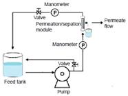
Methods: the dope solution was prepared from the dissolution of the PES with NMP solvent under mechanical stirring for 1 h at a speed of 1000 rpm. It was then added to the solution SiC, Al2O3 and PVP. The resulting mixture containing 47.5 wt% of SiC, 2.5 wt% of Al2O3, 2.5 wt% of PVP, 10 wt% of PES, and 37.5 wt% of NMP was stirred by 30 min at a speed of 300 rpm. Alumina was used as a sintering agent in order to reduce the maximum sintering temperature 2929 P.K. Lin, D.S. Tsai, J. Am. Ceram. Soc. 80 (1997) 365.)- (3131 M. Fukushima, Y. Zhou, Y.I. Yoshizawa, J. Membr. Sci. 339 (2009) 78.. The hollow fiber membranes were extruded in wire form through the technique of precipitation-immersion (Fig. 1). The processing conditions are shown in Table I. The flow of the internal liquid (distilled water) was kept fixed at 350 mL/h with the aid of a syringe pump (SP900Vet, Centaurus Medical). For the bath of precipitation, distilled water was used and the process was made at room temperature in air. The distance between the extruder outlet and the coagulation bath (air gap) was 10 cm. After processing, the fibers were immersed in water for 24 h for solvent output. Then, the hollow fibers were dried at room temperature and sintered at 1450 and 1500 °C, with a heating rate of 2 °C/min up to 500 °C and 5 °C/min up to the final temperature, without controlled atmosphere, in a conventional electric oven (Maitec Fornos Inti). After the heat treatment, the fibers were cut to the length of 5 cm, for the assembly of the modules.

Schematic representation of the laboratory system used to prepare the SiC hollow fiber membranes.
Characterizations: the membranes were characterized by X-ray diffraction (XRD) using a diffractometer (XRD-6000, Shimadzu) with CuKα radiation (λ=1.5418 Å) at 40 kV, 30 mA, scan from 5° to 80°, and scanning rate of 2 °/min. For the morphological characterization of the membranes, a scanning electron microscope (SEM, Superscan SSX 550, Shimadzu) operating at 15 kV was used. The surface topography and the relative surface roughness of the prepared membranes were examined using an atomic force microscope (AFM, mod. 9700, Shimadzu), using the dynamic mode at a scan rate of 1 Hz. The membranes were fixed on a support, scanned in a 15x15 μm area, and analyzed with the SPM Manager program. The topographic images were used to calculate the area roughness average (Ra) of the membrane by:
The porosity and pore size of the membranes was obtained by mercury porosimetry (Autopore IV, Micromeritics). A test machine (Emic) was used to determine the tensile strength of the membranes, which was determined using a three-point bending apparatus with a load cell of 5 kN at a crosshead speed of 0.5 mm/min until fracture. The bending strength was calculated by:
where F is the force at which the fracture of specimen took place, L is the span (40 mm), and Do and Di are the outer and inner diameters of the hollow fiber, respectively; for each sample, ten specimens were tested. For the flow measurement test with distilled water, a bench system with a tangential flow at pressures of 100 and 200 kPa and room temperature (25 °C) was used. In the system to collect the permeate flow, a reservoir for the effluent, a centrifugal pump, a module, two valves, and two manometers were used to measure the pressure of the effluent flow in the system (Fig. 2). The volumetric flow (J) collected for all membranes was calculated by:
The same system was used for the tests with the textile effluent. The indigo blue solution was prepared at the concentration of 10000 ppm. The test of turbidity was performed on a portable turbidimeter (Hanna) and the color test with a colorimeter (Policontrol).
RESULTS AND DISCUSSION
Fig. 3 presents the mineralogical phases identified by X-ray diffraction of the membranes after sintering at 1500 and 1450 °C. The peaks referring to α-silicon carbide phase (34°, 36°, 38° and 42°) identified by the JCPDS 73-1663 file 3232 V.A. Izhevskyi, L.A. Genova, A.H.A Bressiani, J.C. Bressiani, Mater. Res. 3 (2000) 131.), (3333 N. Nikkam, M. Saleemi, E.B. Haghighi, M. Ghanbarpour, R. Khodabandeh, M. Muhammed, M.S. Toprak, Nano-Micro Lett. 6 (2014) 178., cristobalite phase of silicon oxide (22°, 28° and 31°) identified by the JCPDS 39-1425 file, and α-alumina phase (35° and 43°) identified by the JCPDS 77-1123 file were observed. These crystalline phases were also observed in other studies 2525 S.S.L. Oliveira, R.S.B. Ferreira, B.A. Araújo, S.S.L. Oliveira, H.L. Lira, E.M. Araújo, Rev. Eletr. Mater. Proces. 11, 3 (2016) 164.), (2727 P. De Wit, E.J. Kappert, T. Lohaus, M. Wessling, A. Nijmeijer, N.E. Benes, J. Membr. Sci. 475 (2015) 480.), (3434 M.C. Fraga, S. Sanches, V.J. Pereira, J.G. Crespo, L. Yuan, J. Marcher, J. Benavente, J. Eur. Ceram. Soc. 370 (2017) 899.. It is possible to observe that with the increase in sintering temperature, an amount of cristobalite was formed, due to the reaction of SiC with oxygen in the air. The cristobalite has a structural arrangement of α phase at low temperature and β phase at high temperature, above 1470 °C 3535 S.R.F. Vlach, Rev. Inst. Geociênc. USP 1 (2002) 1..

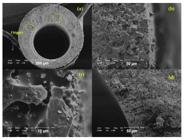
Fig. 4a illustrates the microstructure of the cross-section of the sintered hollow fiber membrane sintered at 1450 °C. It was possible to observe an asymmetric structure that consisted of a spongy region with voids similar to ‘fingers’, which is a typical structure for the hollow fibers prepared by the spinning method and were generated due to the rapid exchange between solvents (NMP) and not solvents 3636 W. Rui, C. Zhang, C. Cai, X. Gu, J. Membr. Sci. 489 (2015) 90.), (3737 G. Chen, H. Qi, W. Xing, N. Xu, J. Membr. Sci. 318 (2008) 38.. The finger-like structure originating from the interior to half of the cross-section provided high porosity to the membrane. Besides that, the porosity was associated with the output of the polymer during the sintering process. In Fig. 4b, it is noted the presence of sharp and irregular grains, characteristic of α-silicon carbide phase, as identified by the X-ray diffraction. According to Nikkam et al. 3333 N. Nikkam, M. Saleemi, E.B. Haghighi, M. Ghanbarpour, R. Khodabandeh, M. Muhammed, M.S. Toprak, Nano-Micro Lett. 6 (2014) 178., the morphology of α-SiC grain may be dominated by the anisotropic crystal structure, allowing the crystal to grow in certain directions more than the other directions. In Fig. 4c, more evidences of irregular and asymmetric shape of the membrane pores are shown. Finally, in Fig. 4d, the cross-sectional image focusing on the surface near the inner part shows that the hollow fiber membrane was porous throughout its section.

The SEM image shown in Fig. 5a illustrates the surface near the outer part of the hollow fiber membrane sintered at 1500 °C. As the membrane sintered at 1450 °C, it was possible to check the presence of ‘fingers’ on the all external surface of the fiber, justifying the high porosity of the hollow fiber membrane. In Fig. 5b, the presence of irregular and asymmetric grains from the formation of silicon carbide is observed. Also, the outermost part of the hollow fiber can work as a porous support layer and the inner part of the membrane as a selective layer, which can increase the flow rate of the permeate. In Fig. 5c, the shape of the grains with irregular and asymmetric morphology is observed. With sintering at 1500 ºC, a continuous phase was clearly present, formed from the SiO2-Al2O3 system. In Fig. 5d, the cross-section close to the inner surface of hollow fiber is verified showing a porous surface. The morphologies identified for the two sintering temperatures indicated that the membranes were porous with irregular and asymmetric morphology. The pores were interconnected and this difference in morphology was responsible for the selectivity of the membrane 3838 J. Nikkola, J. Sievänen, M. Raulio, J. Wei, J. Vuorinen, C.Y. Tang, J. Membr. Sci. 450 (2014) 174..
The asymmetric morphology in the microstructure of the SiC hollow fiber membranes can be attributed to the rapid precipitation during the spinning process, which occurred in the core side which resulted in small channels and slow precipitation in the external side in the hollow fiber forming a spongy structure. Such morphology is typical for inorganic hollow fiber membranes prepared by the precipitation-immersion method 1010 X. Tan, S. Liu, K. Li, J. Membr. Sci. 188 (2001) 87.), (3939 B. Kingsbury, K. Benjamin, J. Membr. Sci. 328 (2009) 134.. The inner and outer diameters as well as the thickness of the sintered ceramic hollow fiber membranes are summarized in Table II. The increase in the sintering temperature from 1450 to 1500 °C led to a reduction in the dimensions of the hollow fiber membranes, which suggested higher densification at the higher sintering temperature.
Fig. 6 shows the AFM images of the membranes sintered at 1450 and 1500 °C. The surfaces of the membranes presented distinct light and dark regions. The dark regions corresponded to areas of low height and the light regions to the highest areas. The concave parts of the images corresponded to the pores 4040 A. Khalid, A. Abdel-Karim, M.A. Atieh, S. Javed, G. Mckay, Sep. Purif. Technol. 190 (2018) 165.), (4141 W. Deng, X. Yu, M. Sahimi, T.T. Tsotsis, J. Membr. Sci. 451 (2014) 192.. It was possible to visualize that with the increase in the sintering temperature, there was an increase in the roughness on the membrane surface; this greater roughness can influence the filtration performance of the membrane since it is related to the pores of the membranes and can retain particles or impurities in membrane effluent treatments. In Fig. 6b, dark spots show this increase in roughness 4040 A. Khalid, A. Abdel-Karim, M.A. Atieh, S. Javed, G. Mckay, Sep. Purif. Technol. 190 (2018) 165.), (4242 H. Cai, H. Fan, L. Zhao, H. Hong, L. Shen, Y. He, J. Chen, J. Colloid Interface Sci. 465 (2016) 33.. The average roughness was quantified and is shown in Table III.
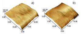
AFM images using dynamic mode (15x15 µm) of the surface of hollow fiber membrane sintered at 1450 °C (a) and 1500 °C (b).
Average roughness, average pore diameter, and porosity for SiC membranes sintered at 1450 and 1500 °C.
Fig. 7 shows the pore size distribution curves of the hollow fiber membranes sintered at 1450 and 1500 °C. SiC membranes sintered at 1450 °C had an average pore size of 4.50 µm and porosity of 57.38% (Table III). The rise in sintering temperature produced an increase in the average pore diameter of the membrane. According to Fukushima et al. 3131 M. Fukushima, Y. Zhou, Y.I. Yoshizawa, J. Membr. Sci. 339 (2009) 78., SiC with alumina showed a limited formation of SiO2-Al2O3 liquid phase during sintering from a thin SiO2 layer, which exists naturally on the surface of SiC particles, and the alumina additive. This liquid covering on the SiC particles may result in a limited mass transfer and the size of the grains increased with the increase of the sintering temperature 4343 J.W. Zhang, H. Fang, J.W. Wang, L.Y. Hao, X. Xu, C.S. Chen, J. Membr. Sci. 450 (2014) 197.. The increase in sintering temperature caused a decrease in porosity and an increase in the size of the remaining pores, as can be seen in Fig. 5, resulting in average pore size of 6.35 µm and porosity of 52.53%.

Volume-based pore size distribution curves by mercury intrusion for 1450 and 1500 °C sintered membranes.
The flexural strength of SiC hollow fiber membranes as a function of the sintering temperature is shown in Fig. 8. It was possible to observe that with the increase in the sintering temperature the membrane became stronger (83.1 MPa at 1450 °C and 98.1 MPa at 1500 °C); this increase was related to the reduction of membrane porosity. When porous ceramics are subjected to mechanical testing, cracks of various orientations can growth, weakening the sample and causing eventual failure 4444 F. Vales, R. Rezakhanlou, C. Olagnon, J. Mater. Sci. 341 (1999) 4081.. The pores act as stress concentrators, causing an increase in potential cracks and fractures 4040 A. Khalid, A. Abdel-Karim, M.A. Atieh, S. Javed, G. Mckay, Sep. Purif. Technol. 190 (2018) 165.), (4444 F. Vales, R. Rezakhanlou, C. Olagnon, J. Mater. Sci. 341 (1999) 4081.. De Wit et al. 2727 P. De Wit, E.J. Kappert, T. Lohaus, M. Wessling, A. Nijmeijer, N.E. Benes, J. Membr. Sci. 475 (2015) 480. showed that for sintering temperatures above 1500 °C the mechanical resistance of the SiC membrane significantly reduces; this loss of strength is attributed to the removal of residual carbon at high processing temperatures, which makes it unfeasible for the production of hollow fiber membranes, which due to the thin walls require high strength to be subjected to high pressures during the treatment of effluents. Therefore, the elevation of the sintering temperature caused the grain growth and liquid phase formation, giving greater densification and increasing the mechanical strength. The membranes prepared with silicon carbide showed an excellent mechanical property, with the flexural strength above 80 MPa, and this was due to the Si-C bonds (Fig. 8). These results were better than the ceramic membranes reported in the literature. Khalid et al. 4040 A. Khalid, A. Abdel-Karim, M.A. Atieh, S. Javed, G. Mckay, Sep. Purif. Technol. 190 (2018) 165. prepared hollow silicon carbide fiber membranes and showed flexural strength of up to 45 MPa, for a sintering temperature of 1500 °C. Oliveira et al. 4545 S.S.L. Oliveira, S.S.L. Oliveira, R.D.S.B. Ferreira, H.D.L. Lira, L.N.D.L. Santana, E.M. Araújo, Mater. Res. 22 (2019) 1. prepared hollow fiber alumina/quartzite residue membranes with a flexural strength between 20 and 82 MPa. Hubadillah et al. 4646 S.K. Hubadillah, M.H.D. Othman, A.F. Ismail, M.A. Rahman, J. Jaafar, Sep. Purif. Technol. 241 (2019) 31. prepared supports of kaolin hollow fiber membrane with strength values between 4 and 15 MPa and Li et al. 4747 L. Li, M. Chen, Y. Dong, X. Dong, S. Cerneaux, S. Hampshire, J. Liu, J. Eur. Ceram. Soc. 36 (2016) 2057. produced hollow fiber membranes of pure alumina with flexural strength values ranging from 14.4±1.1 to 38.1±3.5 MPa sintered at 1500 and 1600 °C, respectively.

Fig. 9a presents the results of the permeated flow with distilled water at pressures of 100 and 200 kPa for membranes sintered at 1450 and 1500 °C. With a pressure of 100 kPa, the membrane presented permeated flow of approximately 4100 L.h-1.m-2, followed by a decrease to 3250 L.h-1.m-2. According to Elmaleh and Naceur 4848 S. Elmaleh, W. Naceur, J. Membr. Sci. 66 (1992) 227. and Hubadillah et al. 4949 S.K. Hubadillah, M.H.D. Othman, A.F. Ismail, M.A. Rahman, J. Jaafar, Y. Iwamoto, M.Z.M. Yusop, Ceram. Int. 44 (2018) 10498., the decrease of water permeated flow over time is due to the stability of water permeate through the membrane pores. The water molecule easily passes through the membrane pores. After some time, the pores are filled with water by the monolayer formation by adsorption of water molecules followed by the condensation of water molecules within the pores, and the flow of water through the membrane starts to become stable. The stability was reached at 2200 L.h-1.m-2 after 35 min of the test. Increasing the pressure to 200 kPa, the permeated flow increased to 2470 L.h-1.m-2 after 35 min of the test. The water permeated flow of the sintered membrane at 1500 °C stabilized at 690 L.h-1.m-2 after 35 min of test, a value that was lower than that of the membrane sintered at 1450 °C. This lower flow value was associated with a smaller apparent porosity of this membrane (52%). With the increase of the pressure to 200 kPa, a behavior similar to that of the membrane sintered at 1450 °C was observed, with permeated flow stabilizing at a higher value of 890 L.h-1.m-2. Both membranes sintered at 1450 and 1500 °C presented high flow when compared to the values in the literature 5050 S.H. Paiman, M.A. Rahman, M.H.D. Othman, A.F. Ismail, J. Jaafar, A.A. Aziz, Ceram. Int. 41, 10 (2015) 12543., which demonstrated the potential of this type of membrane for wastewater treatments.

Permeate flow with distilled water (a) and textile effluent (b) for the SiC hollow fiber membrane sintered at 1450 and 1500 °C.
Fig. 9b presents the results of the permeated flow with textile effluent at pressures of 100 and 200 kPa for membranes sintered at 1450 and 1500 °C. With the pressure of 100 kPa, it was observed that the membrane sintered at 1450 °C presented permeate flow higher than 1970 L.h-1.m-2 in the first minutes of the test. Then the permeated flow dropped and stabilized at 577 L.h-1.m-2; this decrease with time was associated with the phenomenon of fouling, due to the accumulation of solutes on the surface of the membrane, causing clogging and decreasing the permeated flow 5151 M.P. Magalhães, F.D.S. Gomes, R.C.D. Modesta, V.M.D. Matta, L.M.C. Cabral, Food Sci. Technol. 25 (2005) 72.. With the increase of pressure to 200 kPa, the permeate flow stabilized at approximately 674 L.h-1.m-2 after 35 min of the test. With the pressure of 100 kPa, the membrane sintered at 1500 °C presented an initial permeated flow of 500 L.h-1.m-2 and stabilized at 327 L.h-1.m-2 after 35 min of the test. The decrease in the permeated flow is typical of membrane processes due to the fouling phenomenon. Increasing the pressure to 200 kPa, the initial permeated flow increased to 600 L.h-1.m-2 and stabilized at 500 L.h-1.m-2 after 35 min of the test. The size and distribution of the pores influence the permeation rate. Molecules or particles can permeate or retain inside the membrane, clogging and locking the pores and consequently decreasing the permeate flow 2727 P. De Wit, E.J. Kappert, T. Lohaus, M. Wessling, A. Nijmeijer, N.E. Benes, J. Membr. Sci. 475 (2015) 480.), (5252 T.T. Silva, R.C. Della Modesta, P.E. das Mercês, V.M. da Matta, L.M.C. Cabral, Pesq. Agropec. Bras. 40, 4 (2005) 419..
Fig. 10 shows images of the textile effluent before and after treatment with the silicon carbide hollow fiber membrane sintered at 1500 °C. For the membranes sintered at 1500 °C, at 100 kPa of pressure, the turbidity and color values reached almost zero (Table IV). For the membranes sintered at 1450 °C, at 100 kPa of pressure, the values of turbidity and color increased in relation to the membranes sintered at 1500 °C; however, considering the initial concentration of the effluent, there was also a significant rejection and high efficiency of the produced SiC hollow fiber membranes. The results indicated that the SiC hollow fiber membrane exhibited high mechanical resistance and water permeability, implying that this membrane has great potential for application in microfiltration processes. Taking textile effluent as an example (Table IV), the rejection and permeability values of the SiC hollow fiber were compared to values presented in the literature (Table V). The flux was higher than the reported results, while >96% dye rejection was maintained. Thus, the SiC membrane prepared through phase inversion technique and low sintering temperature offers some advantages compared with the other membranes, such as high mechanical resistance, high permeated flow, and selectivity.

Images of textile effluent before and after treatment with SiC hollow fiber membrane sintered at 1450 and 1500 °C.
Turbidity and color of the textile effluent before and after SiC hollow fiber membrane treatment.
Comparison of ceramic hollow fiber membranes prepared from different materials and with different applications reported in the literature.
CONCLUSIONS
Silicon carbide hollow fiber membranes were successfully prepared by the precipitation-immersion technique. The membranes presented crystalline phases of silicon carbide and aluminum oxide when sintered at 1450 and 1500 °C. The SEM images evidenced a porous and uniform surface for the membrane sintered at 1450 °C and a selective porous surface layer when sintered at 1500 °C. The increase of the sintering temperature increased the surface roughness. The membranes sintered at 1450 and 1500 °C presented high porosity (57% and 52%, respectively). The permeate flow measurements indicated the feasibility of the membranes for separation processes. The turbidity and color tests confirmed the viability of the use of the SiC hollow fiber membrane for the textile effluent treatment. The membranes of silicon carbide hollow fibers sintered at 1500 °C were more efficient than those sintered at 1450 °C. The application of these membranes to microfiltration processes is feasible since the process ensures the high quality of the final effluent.
ACKNOWLEDGMENTS
The authors would like to acknowledge the CNPq and CAPES for financial support.
REFERENCES
-
1A.C. Habert, C.P. Borges, R. Nobrega, “Processos de separaçao com membranas”, E-papers Ed., Rio Janeiro (2006).
-
2R.W. Baker, Membr. Technol. Appl. 3 (2004) 1.
-
3B.K. Nandi, R. Uppaluri, M.K. Purkait, Appl. Clay Sci. 42, 1-2 (2008) 102.
-
4E.C. Hammel, O.L.R. Ighodaro, O.I. Okoli, Ceram. Int. 40, 10 (2014) 15351.
-
5A. Huang, N. Wang, J. Caro, J. Membr. Sci. 389 (2012) 272.
-
6D.A. Fedosov, A.V. Smirnov, V.V. Shkirskiy, T. Voskoboynikov, I.I. Ivanova, J. Membr. Sci. 486 (2015) 189.
-
7L.P. Bessa, E.D.P. Ferreira, F.D.S. Magalhães, F.B. Ferreira, V.L. Cardoso, M.H.M. Reis, Ceram. Int. 45, 17 (2019) 23632.
-
8T. Wang, Y. Zhang, G. Li, H. Li, Front. Chem. Eng. China 3, 3 (2009) 265.
-
9A. Huang, B. Feng, J. Membr. Sci. 548 (2018) 59.
-
10X. Tan, S. Liu, K. Li, J. Membr. Sci. 188 (2001) 87.
-
11H. Fang, J.F. Gao, H.T. Wang, C.S. Chen, J. Membr. Sci. 403 (2012) 41.
-
12J.M. Benito, A. Conesa, M.A. Rodríguez, Bol. Soc. Esp. Ceram. V. 43 (2004) 829.
-
13H.P. Hsieh, Inorganic membranes for separation and reaction, Elsevier, Amsterdam (1996).
-
14L.G. Ceballos-Mendivil, R.E. Cabanillas-Lopez, J.C. Tanori-Cordova, R. Murrieta-Yescas, C.A. Perez-Rabago, H.I. Villafan-Vidales, C.A. Estrada, Sol. Energy 116 (2015) 238.
-
15L. Hozer, J.R. Lee, Y.M. Chiang, Mater. Sci. Eng. 195 (1995) 131.
-
16Y. Yang, W. Xu, F. Zhang, Z.X. Low, Z. Zhong, W. Xing, J. Membr. Sci. 541 (2017) 500.
-
17A. Gubernat, L. Stobierski, P. Łabaj, J. Eur. Ceram. Soc. 27 (2007) 781.
-
18J.H. She, T. Ohji, Mater. Chem. Phys. 80 (2003) 610.
-
19S. Ding, S. Zhu, Y. Zeng, D. Jiang, Ceram. Int. 32 (2006) 461.
-
20Y.C. Xu, X.Q. Cheng, J. Longo, L. Shao, J. Membr. Sci. 497 (2016) 77.
-
21M.J. Geerken, M.N.W. Groenendijk, R.G.H. Lammertink, M. Wessling, J. Membr. Sci. 310 (2008) 374.
-
22K.M.D. Medeiros, E.M. Araújo, H.D.L. Lira, D.D.F. Lima, C.A.P.D. Lima, Mater. Res. 20, 2 (2017) 308.
-
23M.H. Armoa, J.M. Jafelicci, Ciênc. Tecnol. 2 (2011) 80.
-
24C. Castel, E. Favre, J. Membr. Sci. 548 (2018) 345.
-
25S.S.L. Oliveira, R.S.B. Ferreira, B.A. Araújo, S.S.L. Oliveira, H.L. Lira, E.M. Araújo, Rev. Eletr. Mater. Proces. 11, 3 (2016) 164.
-
26N. Kamoun, W. Hajjeji, R. Abid, M.A. Rodriguez, F. Jamoussi, Cerâmica 66, 380 (2020) 386.
-
27P. De Wit, E.J. Kappert, T. Lohaus, M. Wessling, A. Nijmeijer, N.E. Benes, J. Membr. Sci. 475 (2015) 480.
-
28M. Dilaver, S.M. Hocaoğlu, G. Soydemir, M. Dursun, B. Keskinler, İ. Koyuncu, M. Ağtaş, J. Clean. Produc. 171 (2018) 220.
-
29P.K. Lin, D.S. Tsai, J. Am. Ceram. Soc. 80 (1997) 365.
-
30M. Fukushima, Y. Zhou, H. Miyazaki, Y. Yoshizawa, K. Hirao, Y. Iwamoto, S. Yamazaki, T. Nagano, J. Am. Ceram. Soc. 89 (2006) 1523.
-
31M. Fukushima, Y. Zhou, Y.I. Yoshizawa, J. Membr. Sci. 339 (2009) 78.
-
32V.A. Izhevskyi, L.A. Genova, A.H.A Bressiani, J.C. Bressiani, Mater. Res. 3 (2000) 131.
-
33N. Nikkam, M. Saleemi, E.B. Haghighi, M. Ghanbarpour, R. Khodabandeh, M. Muhammed, M.S. Toprak, Nano-Micro Lett. 6 (2014) 178.
-
34M.C. Fraga, S. Sanches, V.J. Pereira, J.G. Crespo, L. Yuan, J. Marcher, J. Benavente, J. Eur. Ceram. Soc. 370 (2017) 899.
-
35S.R.F. Vlach, Rev. Inst. Geociênc. USP 1 (2002) 1.
-
36W. Rui, C. Zhang, C. Cai, X. Gu, J. Membr. Sci. 489 (2015) 90.
-
37G. Chen, H. Qi, W. Xing, N. Xu, J. Membr. Sci. 318 (2008) 38.
-
38J. Nikkola, J. Sievänen, M. Raulio, J. Wei, J. Vuorinen, C.Y. Tang, J. Membr. Sci. 450 (2014) 174.
-
39B. Kingsbury, K. Benjamin, J. Membr. Sci. 328 (2009) 134.
-
40A. Khalid, A. Abdel-Karim, M.A. Atieh, S. Javed, G. Mckay, Sep. Purif. Technol. 190 (2018) 165.
-
41W. Deng, X. Yu, M. Sahimi, T.T. Tsotsis, J. Membr. Sci. 451 (2014) 192.
-
42H. Cai, H. Fan, L. Zhao, H. Hong, L. Shen, Y. He, J. Chen, J. Colloid Interface Sci. 465 (2016) 33.
-
43J.W. Zhang, H. Fang, J.W. Wang, L.Y. Hao, X. Xu, C.S. Chen, J. Membr. Sci. 450 (2014) 197.
-
44F. Vales, R. Rezakhanlou, C. Olagnon, J. Mater. Sci. 341 (1999) 4081.
-
45S.S.L. Oliveira, S.S.L. Oliveira, R.D.S.B. Ferreira, H.D.L. Lira, L.N.D.L. Santana, E.M. Araújo, Mater. Res. 22 (2019) 1.
-
46S.K. Hubadillah, M.H.D. Othman, A.F. Ismail, M.A. Rahman, J. Jaafar, Sep. Purif. Technol. 241 (2019) 31.
-
47L. Li, M. Chen, Y. Dong, X. Dong, S. Cerneaux, S. Hampshire, J. Liu, J. Eur. Ceram. Soc. 36 (2016) 2057.
-
48S. Elmaleh, W. Naceur, J. Membr. Sci. 66 (1992) 227.
-
49S.K. Hubadillah, M.H.D. Othman, A.F. Ismail, M.A. Rahman, J. Jaafar, Y. Iwamoto, M.Z.M. Yusop, Ceram. Int. 44 (2018) 10498.
-
50S.H. Paiman, M.A. Rahman, M.H.D. Othman, A.F. Ismail, J. Jaafar, A.A. Aziz, Ceram. Int. 41, 10 (2015) 12543.
-
51M.P. Magalhães, F.D.S. Gomes, R.C.D. Modesta, V.M.D. Matta, L.M.C. Cabral, Food Sci. Technol. 25 (2005) 72.
-
52T.T. Silva, R.C. Della Modesta, P.E. das Mercês, V.M. da Matta, L.M.C. Cabral, Pesq. Agropec. Bras. 40, 4 (2005) 419.
-
53N.M. Terra, G.S. Madrona, F.B. Ferreira, V.L. Cardoso, M.H.M. Reis, Food Bioproc. Tech. 12, 1 (2019) 27.
-
54M. Lee, B. Wang, K. Li, J. Membr. Sci. 503 (2016) 48.
-
55J.W. Zhang, H. Fang, L.Y. Hao, X. Xu, C.S. Chen, Mater. Lett. 68 (2012) 457.
-
56T.L.A. Barbosa, F.M.N. Silva, A.S. Barbosa, E.G. Lima, M.G.F. Rodrigues, Cerâmica 66, 378 (2020) 137.
Publication Dates
-
Publication in this collection
17 May 2021 -
Date of issue
Apr-Jun 2021
History
-
Received
14 Sept 2020 -
Reviewed
26 Oct 2020 -
Reviewed
12 Dec 2020 -
Accepted
16 Dec 2020


