
 Fault-Tolerant Control System Based on Adaptive Neural Network Observer with Structural Damage in Aircraft
ABSTRACT
This paper proposes an accurate mathematical model and a fault-tolerant control system (FTCS) with an adaptive neural network (ANN) observer that considers structural damage of an aircraft. Structural damage causes substantial variations in aerodynamic coefficients and mass properties. Due to these variations, the mathematical modeling of a damaged aircraft becomes highly challenging. Moreover, since the aircraft flight control system has a fixed architecture, changes in the aircraft model may lead to instability. In order to accurately model damaged aircraft, a new uncertainty term and a damage severity coefficient have been defined as damage parameters. Based on the proposed model, an FTCS is developed, which combines an ANN observer with a modified nonlinear dynamic inversion (NDI) controller. The ANN observer is utilized for real-time estimation of damage parameters. Afterwards, the dynamic inversion control law is reconfigured based on the estimated damage parameters. The simulation results demonstrate the impact of the uncertainty parameter on the flight control system and verify the effectiveness of the proposed method under damage to the vertical tail.
Keywords
Fault-tolerant control; Nonlinear dynamic inversion controller; Adaptive neural network observer; Vertical tail damage; Damage parameters
INTRODUCTION
The vertical tail is one of the most essential aerodynamic surfaces in an aircraft. Its primary control function is to maintain the directional stability of the aircraft and prevent yaw oscillations. Therefore, any structural damage to the vertical tail has severe consequences on aircraft flight dynamics (Miao et al. 2020). Aviation accident investigations have demonstrated that structural damage to the fuselage and control surfaces poses the most critical safety risk to aircraft. Aviation accident reports have shown that the most significant danger to aircraft safety is structural damage to the fuselage and control surfaces. For example, Japan Airlines Boeing 747 Flight 123 suffered a sudden depressurization during flight and crashed in a mountainous area due to a vertical tail fracture, killing 520 people. In another similar instance, an American Airlines Airbus 300 lost its vertical stabilizer. As a result of this incident, the aircraft crashed, and 265 people died (Board 2001). There are many such cases in which damage to the aircraft’s tail, wing, or engine has caused fatal accidents.
One effective method to eliminate or reduce the effects of faults is to design a fault-tolerant control system (FTCS). In FTCS, the controller ensures the system stability and proper performance by detecting the fault (Zhang and Jiang 2008). The FTCS can be classified into two primary categories: passive and active (Abbaspour et al. 2020; Fourlas and Karras 2021; Zhang and Jiang 2008). A passive FTCS employs a fixed control architecture designed to maintain stability against predefined system faults. In contrast, active fault-tolerant control systems (AFTCS) operate based on faults occurring in the system. In AFTCS, a fault diagnosis (FD) unit identifies both the location and magnitude of faults. Also, a supervision unit determines the appropriate modifications to the control structure and parameters to compensate for system faults; hence, a key advantage of AFTC schemes is their ability to maintain nominal performance without apparent degradation (Abbaspour et al. 2020).
Generally, in the case of FTCS with structural damage, research work includes damage modeling and the design of a reconfigurable controller. Fault modeling of a damaged aircraft is particularly significant in FTCS design. Bacon and Gregory (2007) have derived the general equations of motion for an asymmetric damaged aircraft. This paper clearly demonstrates the differences in equations of motion between damaged and healthy aircraft, and changes in terms of inertia moments and aerodynamic coefficients. In the papers by Hugo (2017), Li and Liu (2012), and Wang et al. (2016) , the effect of structural damage has been specifically investigated on aerodynamic coefficients and stability derivatives. Li and Liu (2012) employed a linear estimation approach to model vertical tail damage in aircraft. The paper by Wang et al. (2016) similarly focuses on vertical/horizontal tail damage modeling and its effects on stability derivatives. In this study, the damaged area of the vertical tail is parameterized, and a nonlinear relationship is established between this parameter and stability derivatives. In the paper by He et al. (2020), the modeling of damaged aircraft is considered challenging due to abrupt variations in system parameters. The study models structural damage to aerodynamic surfaces (such as wings or tails) as a disturbance term in the aircraft’s equations.
On the other hand, numerous studies in the FTCS literature have investigated controller design methodologies under structural damage conditions. In the studies by Asadi and Ahmadi (2020), Ijaz et al. (2019a; b), and Li et al. (2023), FTCS design has been developed using robust control methodologies. Li et al. (2023) propose an FTCS framework addressing nonlinear wing damage effects. The presented FTCS integrates incremental nonlinear dynamic inversion (NDI) with L₁ adaptive control. In Asadi and Ahmadi’s (2020) article, the design of a nonlinear robust control scheme integrated with NDI control law to enhance stability and flight quality of a model aircraft experiencing left wing damage. Many studies have employed adaptive control methods to design FTCS (He et al. 2020; Miao et al. 2020; Lee et al. 2024; Li et al. 2025; Wang et al. 2016). Wang et al. (2016) propose an AFTCS based on model reference adaptive control (MRAC) for aircraft with vertical tail damage. The study focuses on damaged aircraft modeling using a damage degree coefficient. The controller reconfiguration is implemented as a hybrid linear quadratic regulator-MRAC architecture, with the specific configuration being determined by the damage modeling approach employed. Miao et al. (2020) use an approach similar to Wang et al. (2016), estimating the damage parameter via an adaptive control law through minimization of a cost function. The aircraft modeling specifically examines horizontal tail fracture effects on stability derivatives. In He et al. (2020), a reconfigurable NDI control structure is proposed for damaged aircraft attitude control. The architecture combines an unknown input observer and a dynamic inversion control law, where fault parameters are estimated as disturbance terms. Lee et al. (2024) present a data-driven FTCS design using sparse online Gaussian process regression to stabilize a wing-damaged aircraft. Based on the proposed method, an NDI controller is introduced to compensate for uncertainties in structural damage conditions.
A literature review of control approaches based on research in damaged aircraft (such as the articles in the previous paragraph) shows that the adaptive control design methods demonstrate more effective compensation for structural damage compared to robust control methods, while requiring less modeling information. This advantage has made adaptive control increasingly attractive to researchers. Nevertheless, this approach requires more extensive computations (Zhang et al. 2018). Also, among nonlinear control methods in FTCS, NDI has been widely employed in numerous studies (Ahmadi et al. 2019; Asadi and Ahmadi 2020; Li et al. 2023). The parameters of this model-based controller are derived from the system model. Consequently, when integrated with an effective FD unit, the parameters adapt appropriately to damage conditions.
The performance of AFTCS critically depends on the accuracy of the FD unit integrated into their design architecture; thus, consequently, a precise FD design with online fault detection capability is essential for effective AFTCS implementation (Abbaspour et al. 2020). Observer-based FD approaches are classified into three main categories: model-based approaches, knowledge-based approaches, and combined model-knowledge-based approaches (Abbaspour et al. 2020). Model-based FD methods can detect faults with minimal computational load, making them suitable for real-time applications. However, their diagnostic accuracy depends on the precision of the system’s mathematical model. Various model-based approaches, such as the Kalman filter, H∞ observer, and sliding mode observer, have been utilized for observer design. Conversely, knowledge-based approaches are independent of the system model representation. However, knowledge-based approaches require substantial training datasets for effective implementation (Abbaspour et al. 2020). Various artificial intelligence approaches have been employed for fault detection (Abbas et al. 2024; Abbaspour et al. 2017; Akhtar et al. 2024a; b; Talebi et al. 2008). To leverage the advantages of both FD-based approaches and mitigate their dependency on model accuracy and computational resources, a hybrid method combining these two techniques is proposed. Talebi et al. (2008) proposed an integrated neural network (NN) with a nonlinear observer to design an FD system addressing both sensor and actuator faults in satellite systems. Abbas et al. (2024) introduced an extended Kalman filter (EKF) approach to enhance the accuracy and response speed of an adaptive NN (ANN) observer. They subsequently developed an EKF-based fault detection system for sensors in nonlinear systems by integrating the ANN observer with a nonlinear observer.
Based on previous discussions, the primary challenge in FTCS design relates to accurate modeling of structural damage. The flight dynamics of structurally damaged aircraft are highly nonlinear and coupled in a flight envelope. In numerous studies, nonlinear effects are incompletely modeled, and motion coupling is neglected by disregarding changes in the center of gravity location and inertia moment matrix. Another crucial challenge is preventing severe degradation of control system performance following structural damage. The main idea proposed in this paper to address these challenges is as follows:
-
In practice, changes in the center of gravity location and inertia matrix are modeled as an additive uncertainty term in the moment equations of the aircraft. Also, the impact of damage on aerodynamic and stability derivatives is considered using a damage severity coefficient based on Wang et al. (2016).
-
A reconfigurable control law is proposed through integration of an ANN observer with an NDI controller. The FD unit employs an active approach combining NN algorithms with an EKF for real-time estimation of damage parameters. Subsequently, the aerodynamic and stability derivatives in the NDI controller are updated based on the identified damage parameters. This method enables an aircraft to maintain structural damage resilience with minimal performance degradation across the entire flight envelope without gain scheduling.
This study extends the damaged aircraft model by incorporating both an uncertainty term and a damage severity coefficient. Simulation results highlight the critical role of uncertainty in system instability, revealing limitations of damage models that account only for the damage coefficient (e.g., Wang et al. [2016]). Furthermore, in contrast to sensor fault characteristics (as discussed in Abbas et al. [2024]), structural damage is associated with strongly nonlinear and highly transient dynamics. Accordingly, the identification of these damage parameters using an ANN observer and its integration with the NDI controller is of significant interest. Within this framework, the controller is reconfigured online based on the estimated damage information.
To implement the proposed methodology, this paper is structured as follows: the second section presents an overview of the proposed FTCS based on structural damage. The damaged aircraft modeling and governing nonlinear equations of motion are presented in the third and fourth sections, respectively. The fifth section elaborates on the vertical tail damage parameter identification method using an ANN algorithm, while the sixth section designs the NDI controller for damage adaptation. To validate the effectiveness of the proposed method, numerical simulations are performed on a Boeing 747’s 6-DOF model. Finally, the concluding remarks are provided.
METHODS
Active fault-tolerant control system structure
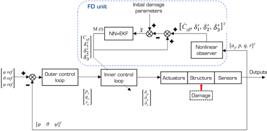
Figure 1 illustrates the overall architecture of the AFTCS for vertical tail damage scenarios. The proposed architecture comprises three main components: 1) aircraft model (including aircraft dynamics, actuators, and sensors); 2) reconfigurable NDI; and 3) FD unit based on an ANN algorithm. In subsequent sections, each of the FTCS components will be analyzed specifically for damage in the vertical tail.
Modelling of damaged aircraft
In a physically symmetric aircraft with a conventional configuration, the nonlinear differential equations of motion are defined about the center of gravity in the body fixed coordinate system, with the cross-product inertia terms Ixy and Iyz neglected. Structural damage compromises the aircraft’s initial geometric symmetry, altering its weight, center of mass location, inertia matrix, aerodynamic coefficients, and stability derivatives. Consequently, reformulation of the 6-DOF aircraft equations of motion becomes necessary. Before presenting the equations, the body fixed coordinate system is defined as shown in Fig. 2. In this coordinate system, the OX axis points toward the nose, OY toward the right wing, and OZ downward.

The 6-DOF model consists of two components: kinetics and kinematics. The kinetic branch describes all forces and moments acting on the aircraft, while the kinematic branch characterizes relative motion variables. Under structural damage, the kinetic branch (force/moment equations) is expressed as follows (Bacon and Gregory 2007).
Force equations
where φ, θ and ψ are roll, pitch, and yaw angles, represents angular velocity about body axes, denotes center of mass displacement, and is the velocity at arbitrary point A. m is the aircraft mass, g is gravitational acceleration, and the terms Σfx, Σfy, and Σfz include the sum of aerodynamic, propulsive, and gravitational forces along body axes. As evident, the shifted center of mass introduces new angular velocity and acceleration terms in the force equations.
Momentum equations
In Equations (4)–(6), the order of the highlighted terms has been changed during typesetting.
where Ixx, Iyy, and Izz are the principal inertia moments, Ixz is the product of inertia moment. Also, ΣMomentx, ΣMomenty, and ΣMomentz represent the sum of aerodynamic, propulsive, and gravitational moments about the body fixed coordinate axes.
The highlighted terms in Eqs. 1-6 demonstrate the differences between the equations of motion for damaged and undamaged aircraft. If and Ixy = Iyz = 0 are assumed, the equations reduce to those of an undamaged aircraft. These equations clearly reveal the increased dynamic complexity and motion coupling in damaged aircraft. Undoubtedly, solving such equations with intricate nonlinear terms presents significant challenges.
Vertical tail damage modeling
The previous section examined the global effects of damage on the force and moment equations of the aircraft. Uncertainties and stability derivative variations are now simultaneously incorporated into the dynamic equations. Accordingly, for vertical tail damage, force and moment equations are first simplified, then augmented with a novel uncertainty term, while stability derivatives are reparametrized using a damage coefficient.
Modeling uncertainties of damage
Achieving flight control system adaptability with damage-induced uncertainties and their resulting motion coupling is nearly impossible. Research has proposed various solutions to this challenge, all sharing a common approach: simplifying the problem by neglecting certain uncertainties, such as center of mass shifts and inertia matrix variations. This study incorporates the following simplifying assumptions to simplify the force and moment dynamic equations:
• A partial failure in the vertical tail leads to changes in the aircraft’s mass (m1) by ∆m, and the displacement of the center of mass along the body fixed X and Z axes; consequently:
• Despite damage to the vertical tail, the aircraft configuration remains symmetric about the XZ plane (Fig. 2), and it can be assumed that:
According to the above assumptions and based on Eqs. 4-6, the uncertainty terms are defined as follows:
The terms δ1, δ2, and δ3 are defined as uncertainties arising from damage to the vertical tail. In fact, these parameters represent the rotational moments generated due to shifts in the aircraft’s center of mass position and are modeled as additive terms in the moment equations. Furthermore, by incorporating the assumptions into Eqs. 1-3, the expressions , and represent the aircraft’s linear accelerations, which are directly measured using accelerometers.
As stated, the most significant changes due to vertical tail damage occur in the moment equations (Eqs. 4-6). These equations will form the basis for modifications to the control system.
Damage stability derivatives
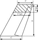
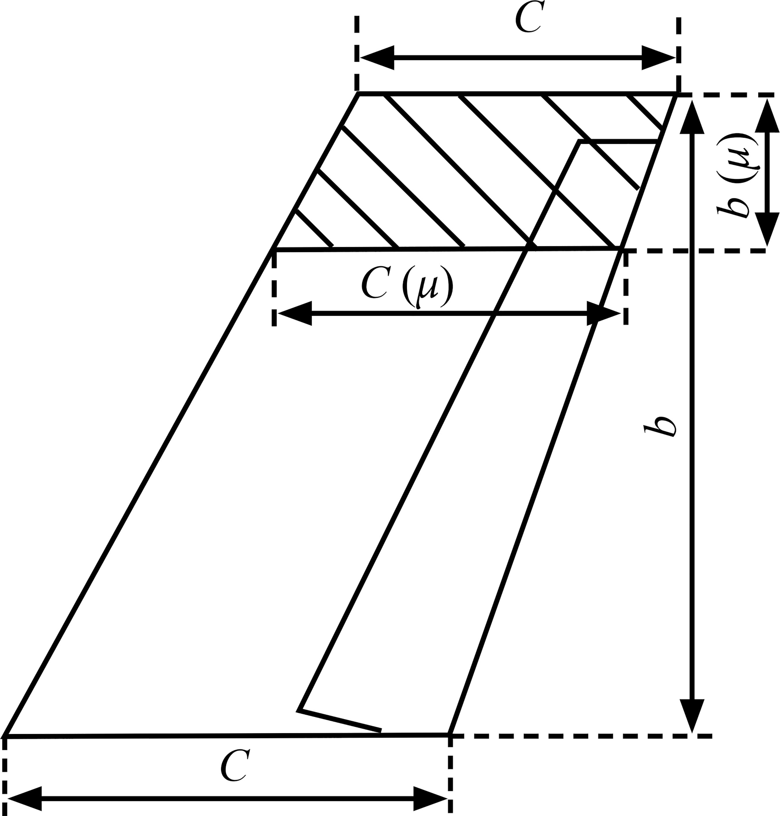
To analyze the impact of damage on stability derivatives, the damage severity must be quantitatively characterized, or, in other words, the damage must be modeled based on the amount of structural fracture. Figure 3 shows the geometric representation of structural damage for a conventional vertical tail.
Definition 1
Damage severity coefficient (μ): the ratio of lost effective area to all effective areas of the vertical tail. According to this definition, the damage severity coefficient (μ) takes values in the range μ ∈ [0,1], where μ = 0 indicates an undamaged flight condition, and μ = 1 represents complete tail loss.
Referring to definition 1 and using the damage geometry (Fig. 3), the damage severity coefficient is expressed as follows (Miao et al. 2020):
The parameters ct, cr, and b represent the vertical tail tip chord length, vertical tail root chord length, and height of the vertical tail, respectively. ct (μ) denotes the tip chord length of the damaged vertical tail, and b (μ) represents the height of the damaged vertical tail. The parameters ct (μ) and b (μ) are calculated as follows (Wang et al. 2016):
where is the exposed area of a trapezoidal vertical tail.
Using Eqs. 13-15, the stability derivative Cyβυ can be modeled in terms of the μ, allowing modification of other stability derivatives. The relationship between the derivative Cyβυ and μ is expressed as follows (Wang et al. 2016):
where , M is the Mach number, Swing is the wing area, Sυref is the vertical tail reference area, is the vertical tail aspect ratio, is the half chord sweep angle, and and is the design factor. Now, other lateral-directional stability derivatives can also be defined in terms of (Roskam 1971; Wang et al. 2016):
The control input derivatives and also vary with the μ. The values of these derivatives under damaged conditions are assumed as follows:
Summary of nonlinear equations for damaged aircraft
In this paper, the proposed model consists of 6-DOF equations of motion represented as first order nonlinear differential equations based on fault parameters. The selected model applies to various flight control systems with structural damage.
The nonlinear equations in body axis coordinate system, assuming a flat earth and considering and , are expressed as follows (Sadati et al. 2007):
The first three equations govern the aircraft’s rotational dynamics, where laero, maero, and naero represent the aerodynamic moment contributions to the aircraft’s rotational motion equations. The second set of three equations represents the equations governing the aircraft’s motion relative to the velocity vector. Here, α, β and ξ are the angle of attack, sideslip angle, and bank angle about the velocity vector, respectively. The third set of three equations describes the rotation of the velocity vector relative to the inertial frame. In these equations, γ is the flight path angle, χ is the velocity vector angle (measured from north), V is the aircraft speed, and L, D, and Y are lift, drag, and side forces. Additionally, represent uncertainties due to vertical tail damage, modeled using Eqs. 4-6, 10-12, as follows:
Fault diagnosis
Real-time identification of fault parameters constitutes a fundamental aspect of adaptive FTCS. The FD unit comprises an estimator (implemented as an observer), which computes the fault parameters μ (or Cy β), . This section describes the fault detection process using an ANN algorithm for a damaged aircraft.
ANN observer
Damage in the vertical tail of aircraft is a nonlinear and unpredictable behavior, making neural NN observers a suitable candidate for fault estimation. Similar to direct NN modeling processes, an ANN observer estimates damage parameters based on nonlinear observer outputs and accelerometer/sensor measurements as follows (Abbaspour et al. 2017):
where represents the nonlinear observer’s state vector and denotes the NN observer at time t, defined as follows (Abbas et al. 2024):
or
where Wi(t) and λi(t) represent the NN input weights at time t, and denotes the sigmoid activation function. From the ANN structure, Ii(t) can be defined as follows:
where τ is the step size, m and n are selected based on the system’s required speed response, and the ANN observer is continuously updated using both observer and NN outputs to detect deviations. ei (t) is deviation of estimated damage parameters from actual values of them. Also, is the bias, where k is the kth sampling instant.
NN weight updating
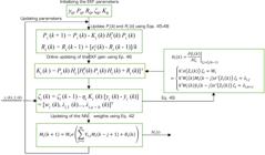
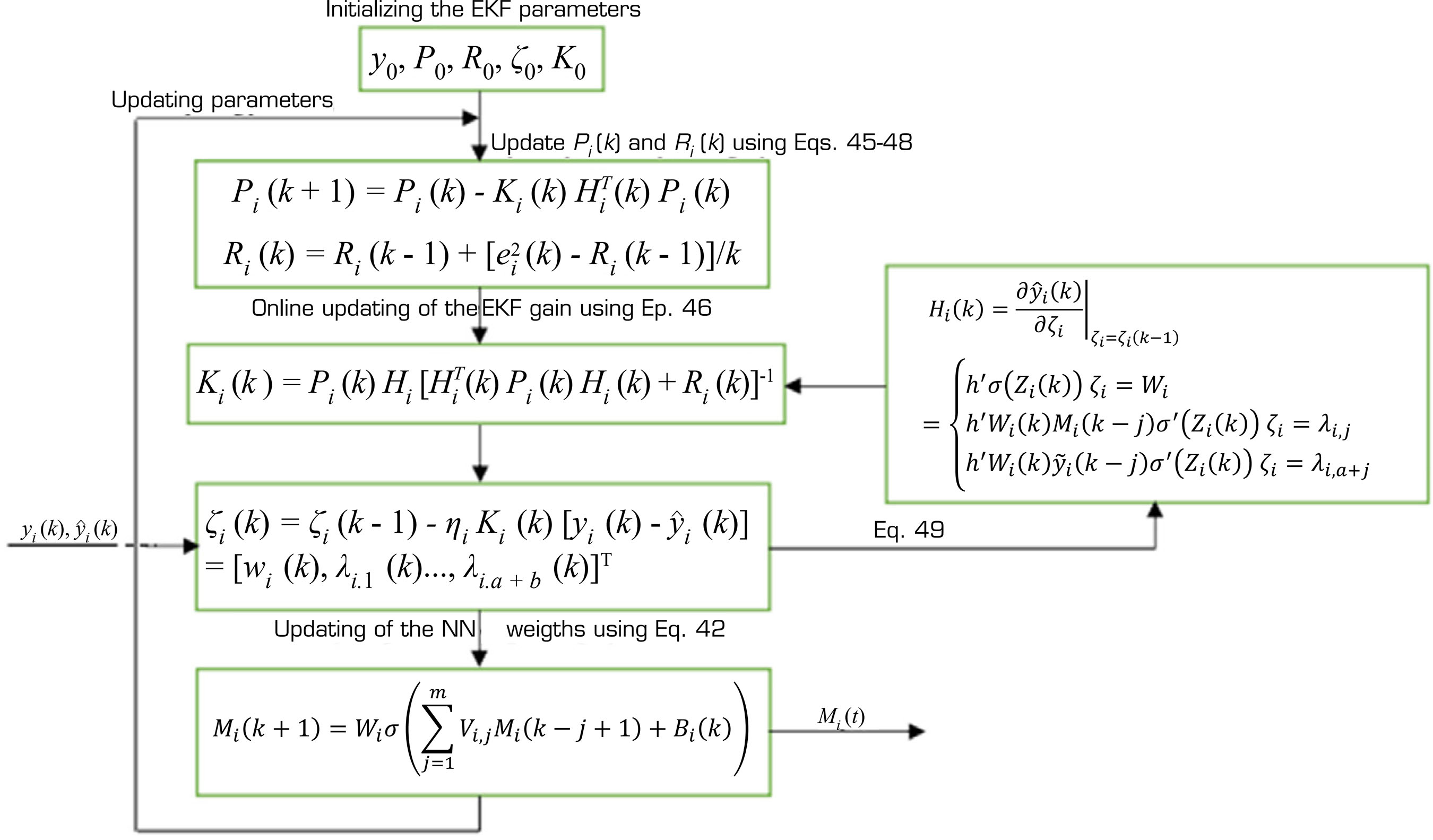
For rapid FD, NN weights should be tuned. This study employs an EKF-based adaptive parameter adjustment algorithm. The EKF updates the NN weight parameters online with a fast-convergence learning rate. The EKF update parameter can be expressed as follows:
The NN weight parameters are updated according to the following EKF-based algorithm as follows (Abbas et al. 2024):
where Ki(k)is the Kalman gain, ηi is the learning coefficient, Pi(k) represents the state estimation error covariance, and Ri(k) is the noise covariance. To compute Ri(k), a recursive method is employed as follows (Abbaspour et al. 2017):
Also, Hi(k) is the partial derivative of with respect to , expressed in terms of the observer’s input as follows:
where
The flowchart of updating ANN gains using EKF is shown in Fig. 4. The ANN employs online learning, meaning it is not pre-trained on fixed data but continuously adapts and updates its parameters during aircraft flight.
Estimation of damage parameters in aircraft
This subsection presents the design process of the proposed FD strategy for the vertical tail damage parameters. To simplify and to keep the AAN observer stable, the following assumptions are considered:
All state variables are measurable or observable.
The magnitudes of Cy β, are bounded.
The modeling uncertainties are bounded.
The state functions f (x(t)) and h (x(t)) are differentiable with respect to the estimated state :
where A (t) is an matrix and C (t) is an matrix. Consequently, the following equations can be derived by expanding f (x(t)) and h (x(t)) with respect to :
where and contain higher-order terms of the state estimation error .
There exist positive real numbers and such that and satisfy the uniform bounds
The symmetric matrix P (t) satisfies the following property:
where β1 and β2 are positive real numbers, and P (t) is the solution to the following Lyapunov equation:
where Q is a positive definite symmetric matrix.
Under these assumptions, the ANN’s stability can be guaranteed, and its proof is fully demonstrable.
Vertical tail damage causes significant changes in aircraft lateral force. According to Eq. 2, these effects are measurable through lateral accelerometer outputs. Consequently, the accelerometer readings provide pilots with direct awareness of damage occurrence. The lateral aerodynamic force acting on the aircraft is calculated as follows:
where ay is the lateral acceleration, q is the dynamic pressure, and Cy is the lateral force coefficient. Direct measurement of Cy β, using sensor modules is infeasible. To initialize the NN observer, the nonlinear observer utilizes gyro outputs (p, q, r) and lateral accelerometer data (ay) as follows:
The ANN observer, by learning these estimated parameters and adapting to their initial values, can perform fault detection and isolation of damage parameters (based on the equation in the previous subsection) (Fig. 4).
NDI controller
Dynamic inversion is a powerful approach that directly accounts for the system’s nonlinearities. This controller utilizes the system’s internal model and input dynamics to cancel out the system’s nonlinearities, enabling subsequent application of a single linear controller for system regulation. Consequently, this approach eliminates the need for gain scheduling across the flight envelope. The simplicity of dynamic inversion architecture enables flexible control design for all flight regimes, making it a preferred method for aircraft flight control under damage conditions (Tol et al. 2016).
The NDI controller, despite its advantages, is only justifiable when there is sufficient time scale separation between the outer loop and inner loop dynamics, and also requires accurate model identification. To address these challenges, with particular emphasis on the damage problem, several solutions have been proposed in the article:
-
The multiple time scale decomposition approach isolates rotational dynamics by assuming their substantially faster response compared to translational dynamics. This paradigm necessarily treats control surfaces as the dominant moment-generating mechanisms, which constitutes a valid assumption for conventional aircraft (Ahmadi et al. 2019).
-
The use of system identification algorithms reduces the controller’s dependence on the system model. In this approach, unknown parameters (damage) are estimated, and the controller dynamically adapts to parameter variations.
During structural damage, the momentum (rotational) and force (translational) equations governing aircraft dynamics are changed, while the position and attitude equations remain unchanged (He et al. 2020). The most significant changes following vertical tail damage occur in the momentum equations. Consequently, designing the inner loop of the control system becomes very important.
Inner loop controller
To apply the dynamic inversion control method, aircraft nonlinear dynamics can be formally expressed as follows:
where x, u, and y define system states, control inputs, and system outputs, respectively. f(x) represents the state function and g(x) represents the control input function. According to Eq. 65, the NDI control law is presented in the following form (Slotine and Li 1991):
where υ is a linear control law implemented as a first-order system with gain K:
As an example, the aircraft’s fast dynamics are given in Eq. 69. In this equation, the variables pc, qc, and rc represent the roll rate, pitch rate, and yaw rate commands, respectively, which are derived using the control law as follows:
Also, the rotational equations of aircraft (Eqs. 28-30) can be arranged by combining both linear and nonlinear terms as Eq. 70:
where is the system state vector and is the aircraft control inputs. By making changes to Eqs. 28-30, the following expressions for the elements of f(x) and g(x) are obtained:
The aerodynamic moments (, and ) are classically computed from aircraft linear stability and control characteristics in Roskam (1998) and by using Eqs. 18-27, can be detailed as follows:
Here, the control system is assumed to receive angular rate derivative commands () and computes the requisite control surface deflections (δa, δe and δr) according to Eq. 67:
By substituting Eqs. 69, 71 and 72 into Eq. 76, the control input u for achieving a linearized system is obtained.
Outer loop controller
In this control loop, the controller is designed to regulate the attitude states (φ, θ and ψ) using the fast dynamics states as control inputs. Similar to the inner loop, the attitude control equations are expressed in the following matrix (Roskam 1998):
where x = [φ, θ, ψ] represents the aircraft attitude state vector. and the functions fφθψ and gφθψ are defined as follows:
where φ, θ and ψ angles are measured by the navigation system. The slow dynamics, analogous to the inner loop case, are given in Eq. 80:
φ, θ and ψ represent the commanded attitude angle inputs, while denote the desired dynamics of the outer loop. Here, the control system is assumed to receive and compute angular rates for sending angular rates (p, q, and r) to the inner loop. These are derived according to Eq. 67 as follows:
where gφθψ is defined according to Eq. 79.
Controller reconfiguration
Using fault information provided by the FD unit, the closed-loop control system’s performance can be improved by online controller adjustment. Therefore, the objective is to modify the NDI control law according to Eq. 76. Specifically, by assigning values to the uncertainties and adjusting the fpqr(x) and g(x) matrices according to in the inner control loop, the control law is updated.
Stability derivatives update
The first step in adapting the control law to damage conditions is updating the stability derivative values. According to Eqs. 71 and 72, the aerodynamic moments and undergo modifications. Therefore, according to Eqs. 73 and 75, modifications are required for lateral/directional stability derivatives (Clβ, Clp, Clr, Cnβ, Cnp, Cnr) and control input derivatives (Clδr, Cnδr). Referring to Eqs. 18-27, these derivatives are adjusted based on the Cy β(μ)which is estimated by the ANN observer.
Damage uncertainty quantification
The quantification of damage-induced uncertainties, combined with the stability derivative corrections, yields a comprehensive control law accounting for damage effects. By estimating uncertainties , , and using the ANN observer and substituting their values into Eq. 76, The inner control loop is updated, and the control law is adapted to damage conditions.
RESULTS
Numerical simulation
To evaluate the damage modeling methodology and the proposed FTCS, the simulations are presented in two separate parts. The first part considers the impact of on the baseline control system’s output. In the second part, the proposed FTCS performance is compared with both A conventional NDI controller and an adaptive NDI (ANDI) controller. The purpose of this section is to demonstrate performance improvements over Miao et al. (2020) and Wang et al. (2016) in both damage modeling and control branches.
The control system’s performance is simulated using the Boeing 747’s 6-DOF model (Roskam 1998). The selected model represents the aircraft’s behavior in steady-state flight at a speed of 205 m·s and an altitude of 6,096 m (20,000 ft). The initial trim conditions are presented in Table 1, while Table 2 contains the physical aircraft specifications, and Table 3 lists the control surface deflection limits.
To evaluate the performance of both the FD unit and control methods, specified fault parameters are injected into the aircraft’s nonlinear model. Due to aircraft energy loss following damage, the damage uncertainty parameters are considered to have negative values () across different μ values. Based on the ANN observer architecture, three separate ANN observers are designed to detect damage parameters. Each ANN consists of an input layer with two nodes, a hidden layer with a sigmoid activation function, and an output layer. The initial weight parameters for each ANN observer are provided in Table 4.
In all simulations, a second-order linear command filter compliant with MIL-STD-1797A has been implemented to satisfy input commands and maintain flight quality requirements. Also, the controller gains for the control loop design are defined as follows:
where K1 denotes the outer loop gain, K2 the inner loop gain, ς the damping ratio, and ωn is the natural frequency. These parameters are specified in Table 5.
Figure 5 demonstrates the performance of the baseline controller under nominal conditions (fault-free). The reference inputs for the specified maneuver are defined as follows:
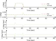
As shown, when a 5 deg step command is applied as a roll input, the response curves accurately track the reference input, and both roll and yaw angles ultimately converge to steady-state values.
Effect of structural damage parameters on system output
As outlined in the introduction, a key contribution of this paper is the development of the damaged aircraft model that takes into account both μ and δ', comparing it with the methods developed in Miao et al. (2020) and Wang et al. (2016), where modeling was performed considering only the μ parameter. Hence, the effects of , and μ are analyzed, and the baseline controller outputs without the FD unit are demonstrated.
Figure 6 presents simulated control system outputs for different μ based on Wang et al. (2016). Following damage initiation at t = 14 sec, adverse effects on ψ gradually manifest in the simulation results. With progressive vertical tail damage, both the ψ and p deviations exhibit increasing divergence from the zero equilibrium. However, the φ demonstrates negligible sensitivity, showing only minor deviation from the reference trajectory at μ = 0.9.

Impact of μ on the NDI controller performance. (a) outer loop; (b) inner loop (δ' = 0). Fault is injected at t = 14 s.
Figure 7a demonstrates the combined effects of damage parameters μ and δ' on roll and yaw angles (proposed method). This flight scenario incorporates progressively increasing μ values while maintaining a constant δ' parameter. As structural damage progresses, the φ and ψ deviations increase relative to the reference trajectory. The most significant difference, and in fact, the initial manifestation of instability in the system, is the steady state error in the final value of ψ. As damage progresses, the deviation of ψ from its initial equilibrium increases, and the output tends toward instability around μ = 0.55. For this reason, adding an FD unit to the control system is essential for real-time damage identification.
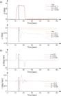
Performance of the NDI controller without the FD unit. (a) outer loop; (b) inner loop (δ' = −2.5 deg/s). Fault is injected at t = 14 s.
A notable observation in Fig. 7, compared to Fig. 6, is the pronounced effect of the δ' parameter on the stability of the control system’s output. This conclusively demonstrates the inadequacy of damage modeling in Miao et al. (2020) and Wang et al. (2016) , which rely solely on the parameter μ.
Performance of the proposed FTCS
In subsequent simulations, the performance of the proposed FTCS (NDI + EKF) is evaluated in comparison to conventional NDI and ANDI controllers. It should be noted that the control structure of the adaptive method, compared to Wang et al. (2016), combines NDI controllers with MRAC. The simulations demonstrate the sufficient performance of the proposed method compared to the Wang et al. (2016) control approach.
To evaluate the proposed method, a damage scenario is considered as follows:
First, the tangible impact of damage on the accelerometer output is analyzed. As shown in Fig. 8, the accelerometer output values are compared between undamaged and damaged conditions; any deviation serves as a warning indicator for damage occurrence in the vertical tail. In the fault detection process, the ANN observer is estimated μ (o variations applied to Cyβ) and δ', as illustrated in Fig. 9.

Comparison of the lateral accelerometer output in undamaged and damaged conditions. A fault is injected at t = 14 sec.

Performance of the ANN observer in damage parameter estimation. A fault is injected at t = 14 sec.
Figure 10a shows a comparative analysis of reference input tracking between the baseline controller (without the FD unit) and the proposed method. The proposed FTCS eliminates yaw angle deviation (and steady state error) from the reference trajectory following damage occurrence. Also, the roll angle deviations are reduced from the reference trajectory compared to the NDI controller.
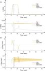
Performance comparison of control methods. (a) outer loop; (b) inner loop: proposed FTCS vs. NDI and ANDI. Fault is injected at t = 14 s.
Figures 10 and 11 clearly demonstrate the superior performance of the proposed FTCS over the ANDI controller. The most significant difference is observed in the control surface deflections shown in Fig. 11. Accordingly, the aileron and rudder actuators in the ANDI method exhibit severe oscillations (in other words, relatively high control effort). These undesirable oscillations are similarly observed in r as shown in Fig. 10b. Furthermore, Fig. 11 demonstrates that the rudder actuator in the adaptive method approaches its negative deflection limit, indicating this controller’s marginal stability when operating under damage conditions.

Comparison of control surfaces deflections: proposed FTCS vs. NDI and ANDI controllers. Fault is injected at t = 14 s.
It should be noted that the oscillations in the ANDI method are due to increasing adaptive gains. These gain variations occur due to the abrupt and severe nature of the structural damage in the vertical tail. In fact, due to the inherently nonlinear nature of structural damage and the abrupt variations in aerodynamic coefficients and derivatives in the aircraft dynamic model, pronounced nonlinear transient dynamics are induced, which significantly challenge the adaptation mechanism. Consequently, to compensate for the resulting aircraft model mismatch, the ANDI controller adopts high adaptive gains and rapidly updates its parameters, which ultimately leads to oscillatory behavior in the system response.
Figure 12 examines the effect of damage parameters on θ. As evident in the simulation results, when the fault occurs at t = 14 sec, adverse effects manifest in variations of θ. The empennage damage induces a steady state error in the NDI controller’s response. With the integration of the FD unit into the control system, the ANN observer has successfully estimated μ and δ'; consequently, the steady state θ error has been eliminated. A notable observation is the presence of undesirable oscillations in elevator control surface deflections with the ANDI controller.

DISCUSSION
The simulation results demonstrate that considering both μ and δ' provides a more realistic representation of structural damage and improves FTCS performance. The proposed ANN-based NDI controller maintains accurate reference tracking while significantly reducing oscillations in the aircraft states and control surfaces after damage. Compared with the conventional NDI and ANDI approaches, the proposed method shows greater robustness under abrupt structural damage by continuously updating the control law based on the estimated fault parameters. These findings indicate that integrating reliable fault estimation with configurable control can effectively enhance the stability and safety of damaged aircraft, although the performance still depends on the accuracy of the observer and the aircraft model.
CONCLUSION
This paper investigates the modeling and control of an aircraft under vertical tail structural damage. Damage modeling was accomplished by defining both a damage severity coefficient (μ) and a damage uncertainty term (δ'). μ and δ' represent the extent of physical damage in the tail and changes in mass properties, respectively. To mitigate damage effects, an AFTCS based on the NDI control law was developed. Fault parameters were estimated using an ANN observer, and the control law was updated based on estimated parameters (without gain scheduling). Fault scenarios in a roll maneuver were simulated for the Boeing 747’s 6-DOF model. In the simulations, the proposed FTCS was compared with a conventional NDI control method and a model reference adaptive NDI method.
Based on the simulation results, (i) the damaged aircraft model exhibits significant dependence on the δ', with this parameter demonstrating a substantial impact on yaw angle variations and causing instability in the system; (ii) the proposed method achieves complete yaw angle reference tracking (zero steady state error) post-damage while simultaneously reducing roll angle deviations from the reference trajectory; (iii) undesirable severe oscillations in rudder and aileron actuators, as well as in roll rate and yaw rate, are eliminated. Notably, all control methods discussed in this paper possess distinct advantages and limitations.
One of the main challenges in FTCS is its integration with other fault types, such as actuator and sensor faults. This results in a more complex mathematical model, increasing the dependency of both the fault detection unit and controller on the system model. Such dependency reduces fault detection and isolation accuracy. To address this issue, future work can focus on control methods with predictive capabilities for future states and on enhancing the fault detection unit through data-driven approaches. In these methods, the NN algorithm can play a critical role in fault isolation and uncertainty decoupling.
ACKNOWLEDGMENTS
Not applicable.
DECLARATION OF USE OF ARTIFICIAL INTELLIGENCE TOOLS
FUNDING
DATA AVAILABILITY STATEMENT
The data will be available upon request.
REFERENCES
-
Abbas M, Sadati S. H, Khazaee M (2024) Fault tolerant control design based on observer-switching and adaptive neural networks for maneuvering aircraft. J Braz Soc Mech Sci Eng 46(12):694. https://doi.org/10.1007/s40430-024-05235-9
» https://doi.org/10.1007/s40430-024-05235-9 -
Abbaspour A, Aboutalebi P, Yen KK, Sargolzaei A (2017) Neural adaptive observer based sensor and actuator fault detection in nonlinear systems: Application in UAV. ISA Trans 67:317-329. https://doi.org/10.1016/j.isatra.2016.11.005
» https://doi.org/10.1016/j.isatra.2016.11.005 -
Abbaspour A, Mokhtari S, Sargolzaei A, Yen KK (2020) A survey on active fault tolerant control systems. Electronics 9(9):1513. https://doi.org/10.3390/electronics9091513
» https://doi.org/10.3390/electronics9091513 -
Ahmadi K, Asadi, Pazooki F (2019) Nonlinear L1 adaptive control of an airplane with structural damage. Proc Inst Mech Eng G J Aerosp Eng 233(1):341-353. https://doi.org/10.1177/0954410017730088
» https://doi.org/10.1177/0954410017730088 -
Akhtar Z, Naqvi SAZ, Hamayun MT, Ijaz S (2024a) A multilayer neural‐network‐based fault estimation and fault tolerant control scheme for uncertain system. Int J Robust Nonlinear Control 34(18):11985-12011. https://doi.org/10.1002/rnc.7604
» https://doi.org/10.1002/rnc.7604 -
Akhtar Z, Naqvi SAZ, Khan YA, Hamayun MT, Ijaz S (2024b) Design and experimental validation of an adaptive multi-layer neural network observer-based fast terminal sliding mode control for quadrotor system. Aerospace 11(10):788. https://doi.org/10.3390/aerospace11100788
» https://doi.org/10.3390/aerospace11100788 -
Asadi D, Ahmadi K (2020) Nonlinear robust adaptive control of an airplane with structural damage. Proc Inst Mech Eng G J Aerosp Eng 234(14):2076-2088. https://doi.org/10.1177/0954410020926618
» https://doi.org/10.1177/0954410020926618 - Bacon B, Gregory I (2007) General equations of motion for a damaged asymmetric aircraft. Paper presented 2007 AIAA Atmospheric Flight Mechanics Conference and Exhibit. AIAA; Hilton Head, USA.
- Board S (2001) In-flight separation of vertical stabilizer American Airlines Flight 587 Airbus Industrie A300-605R, N14053, Belle Harbor, New York November 12, 2001. Washington (DC): National Transportation Safety Board.
-
Fourlas GK, Karras GC (2021) A survey on fault diagnosis and fault tolerant control methods for unmanned aerial vehicles. Machines 9(9):197. https://doi.org/10.3390/machines9090197
» https://doi.org/10.3390/machines9090197 -
He Q, Tan Y, Liu X, Jia Q, Liu J (2020) Reconfigurable nonlinear dynamic inversion for attitude control of a structurally damaged aircraft. IEEE Access 8:199931-199943. https://doi.org/10.1109/ACCESS.2020.3035436
» https://doi.org/10.1109/ACCESS.2020.3035436 -
Hugo G (2017) Autonomous landing of a fixed Wing unmanned aircraft with partialwing and stabiliser losses (doctoral dissertation). Stellenbosch: Stellenbosch University. In English. https://scholar.sun.ac.za/bitstream/handle/10019.1/101035/hugo_autonomous_2017.pdf
» https://scholar.sun.ac.za/bitstream/handle/10019.1/101035/hugo_autonomous_2017.pdf -
Ijaz S, Hamayun MT, Yan L, Shi C (2019a) Active fault-tolerant control for vertical tail damaged aircraft with dissimilar redundant actuation system using integral sliding mode control. Proc Inst Mech Eng C J Mech Eng Sci 233(7):2361-2378. https://doi.org/10.1177/0954406218790280
» https://doi.org/10.1177/0954406218790280 -
Ijaz S, Yan L, Hamayun MT, Shi C (2019b) Active fault tolerant control scheme for aircraft with dissimilar redundant actuation system subject to hydraulic failure. J Franklin Inst 356(3):1302-1332. https://doi.org/10.1016/j.jfranklin.2018.11.018
» https://doi.org/10.1016/j.jfranklin.2018.11.018 -
Lee JD, Kim L, Zewge NS, Bang H (2024) Fault tolerant control for aircraft with structural damage using sparse online Gaussian process regression. Int J Aeronaut Space Sci 25:1067-1091. https://doi.org/10.1007/s42405-024-00715-7
» https://doi.org/10.1007/s42405-024-00715-7 -
Li K, Shi J, Liu X, Zhu H, Wang L (2025) Research on adaptive nonlinear dynamic inversion fault tolerant flight control system based on sideslip trim strategy. Aircr Eng Aerosp Technol 97(4):369-381. https://doi.org/10.1108/AEAT-08-2024-0233
» https://doi.org/10.1108/AEAT-08-2024-0233 -
Li X, Liu HH (2012) A passive fault tolerant flight control for maximum allowable vertical tail damaged aircraft. J Dyn Syst Meas Control 134(3):031006. https://doi.org/10.1115/1.4005512
» https://doi.org/10.1115/1.4005512 -
Li Y, Liu X, Ming R, Zhu H, Zhang W (2023) A cascaded nonlinear fault tolerant control for fixed wing aircraft with wing asymmetric damage. ISA Trans 136:503-524. https://doi.org/10.1016/j.isatra.2022.10.021
» https://doi.org/10.1016/j.isatra.2022.10.021 -
Miao Y, Wang X, Miao Y, Wang S (2020) Dynamics and adaptive fault-tolerant flight control under structure damage of horizontal stabilizer. Aerosp Sci Technol 106:106135. https://doi.org/10.1016/j.ast.2020.106135
» https://doi.org/10.1016/j.ast.2020.106135 - Roskam J (1971) Methods for estimating stability and control derivatives of conventional subsonic airplanes. Kansas: Roskam Aviation and Engineering Corporation.
- Roskam J (1998) Airplane flight dynamics and automatic flight controls. Kansas: DARcorporation.
-
Sadati SH, SabzeParvar M, Menhaj MB, Bahrami M (2007) Backstepping controller design using neural networks for a fighter aircraft. Eur J Control 13(5):516-526. https://doi.org/10.3166/ejc.13.516-526
» https://doi.org/10.3166/ejc.13.516-526 - Slotine J-JE, Li W (1991) Applied nonlinear control. New Jersey: Prentice-Hall.
-
Talebi H. A, Khorasani K, Tafazoli S (2008) A recurrent neural-network-based sensor and actuator fault detection and isolation for nonlinear systems with application to the satellite’s attitude control subsystem. IEEE Trans Neural Netw 20(1): 45-60. https://doi.org/10.1109/TNN.2008.2004373
» https://doi.org/10.1109/TNN.2008.2004373 -
Tol H, de Visser CC, Sun L, Van Kampen E, Chu Q (2016) Multivariate spline-based adaptive control of high-performance aircraft with aerodynamic uncertainties. J Guid Control Dyn 39(4):781-800. https://doi.org/10.2514/1.G001079
» https://doi.org/10.2514/1.G001079 -
Wang J, Wang S, Wang X, Shi C, Tomovic MM (2016) Active fault tolerant control for vertical tail damaged aircraft with dissimilar redundant actuation system. Chin J Aeronaut 29(5):1313-1325. https://doi.org/10.1016/j.cja.2016.08.009
» https://doi.org/10.1016/j.cja.2016.08.009 -
Zhang J, Yang X, Yang L (2018) Virtual-command-based model reference adaptive control for abrupt structurally damaged aircraft. Aerosp Sci Technol 78:452-460. https://doi.org/10.1016/j.ast.2018.04.043
» https://doi.org/10.1016/j.ast.2018.04.043 -
Zhang Y, Jiang J (2008) Bibliographical review on reconfigurable fault tolerant control systems. Annu Rev Control 32(2): 229-252. https://doi.org/10.1016/j.arcontrol.2008.03.008
» https://doi.org/10.1016/j.arcontrol.2008.03.008

 Source: Elaborated by the authors.
 Source: Elaborated by the authors.
 Source: Elaborated by the authors.
 Source: Elaborated by the authors.
 Source: Elaborated by the authors.
 Source: Elaborated by the authors
 Source: Elaborated by the authors
 Source: Elaborated by the authors.
 Source: Elaborated by the authors.
 Source: Elaborated by the authors.
 Source: Elaborated by the authors.
 Source: Elaborated by the authors.