 Design and Optimization of an Acoustic Levitator for Experimental Rocketry
ABSTRACT
This study presents the design and preliminary laboratory validation of an acoustic levitator intended for future integration into the payload bay of an experimental rocket. The work aims to explore the feasibility of acoustic levitation as a contactless particle-handling system for experimental rocketry. The research combined a theoretical review, prototype design, numerical acoustic simulation, RocketPy-based flight-condition simulation, and laboratory testing of a small-scale acoustic levitation system. The prototype was evaluated under controlled static laboratory conditions using a 40 kHz ultrasonic configuration. The prototype achieved particle suspension under laboratory conditions. The system was configured with 36 ultrasonic transducers arranged in two opposed arrays, a 12 V DC power supply, and a transparent acrylic chamber for particle observation. AKBAL-II flight simulations defined preliminary environmental conditions, including peak acceleration, atmospheric pressure variation, estimated vibration range, parachute events, and total flight time. The results support the preliminary feasibility of the proposed acoustic levitation system at the prototype level. However, in-flight operation has not yet been experimentally validated and remains future work. Further testing is required to evaluate vibration resistance, pressure effects, thermal behavior, energy consumption, repeatability, and stability under representative flight conditions.
Keywords
Acoustic levitation; Acoustic resonance; Acoustic simulation; Ultrasonic radiation; Payload integration; Rockets
INTRODUCTION
Acoustic levitation is a technique that employs sound waves to generate a holding force capable of suspending and manipulating particles without physical contact. This phenomenon has been widely studied across various scientific and technological fields – including biology, chemistry, and physics – because of its ability to handle small particles under microgravity conditions or without direct contact. The first acoustic levitation experiments, conducted by Bücks and Müller (1933), used ultrasonic sound waves (ranging from 20 to 100 kHz) to trap small particles through standing waves. Over time, technological advances enabled not only the suspension of particles but also their manipulation, rotation, and transport, thereby expanding applications to areas such as chemical reactions between droplets (Vasileiou et al. 2016), liquid dehydration (Pajander et al. 2015), and, more recently, experiments with particles in microgravity environments.
Despite these advances, the application of acoustic levitation beyond controlled environments has remained limited, and its implementation in engineering research and projects – such as experimental rocketry – has not yet been widely explored. This limitation is primarily due to the challenges posed by the extreme acceleration and vibration conditions experienced during a rocket flight. Nevertheless, the potential of acoustic levitation for innovative applications in this field is considerable.
In this context, the proposal was to design an acoustic levitator capable of stabilizing a particle within the payload bay of an experimental rocket during flight. The working hypothesis is that if a particle can remain suspended inside the levitation chamber under representative flight conditions, acoustic levitation could eventually be incorporated into experimental rocketry as a contactless particle-handling strategy. However, the present study is limited to prototype design, simulation, and static laboratory validation.
Currently, the project is in the development phase at several stages. Although significant progress has been achieved in certain processes – such as the selection of suitable acoustic components and the preliminary design of the system – several challenges remain to be addressed. Some of the initial procedures have already been exhausted, yet further work is required on integrating the acoustic levitation system with the dynamic conditions of rocket flight, as well as on optimizing the stability and accuracy of particle suspension under extreme vibration. It is expected that, as these stages advance, the project will be able to achieve its objective of demonstrating a novel application of acoustic levitation beyond controlled laboratory environments.
This work is carried out with the support of students from the Sociedad Aeroespacial de la Facultad de Ingeniería at the Universidad Autónoma del Estado de México in designing an acoustic levitator capable of stabilizing a particle during the flight of an experimental rocket. If the design proves successful, it will represent a significant innovation that could contribute to the advancement of the discipline while expanding the technological possibilities for studying physical phenomena in rocket flights.
Background
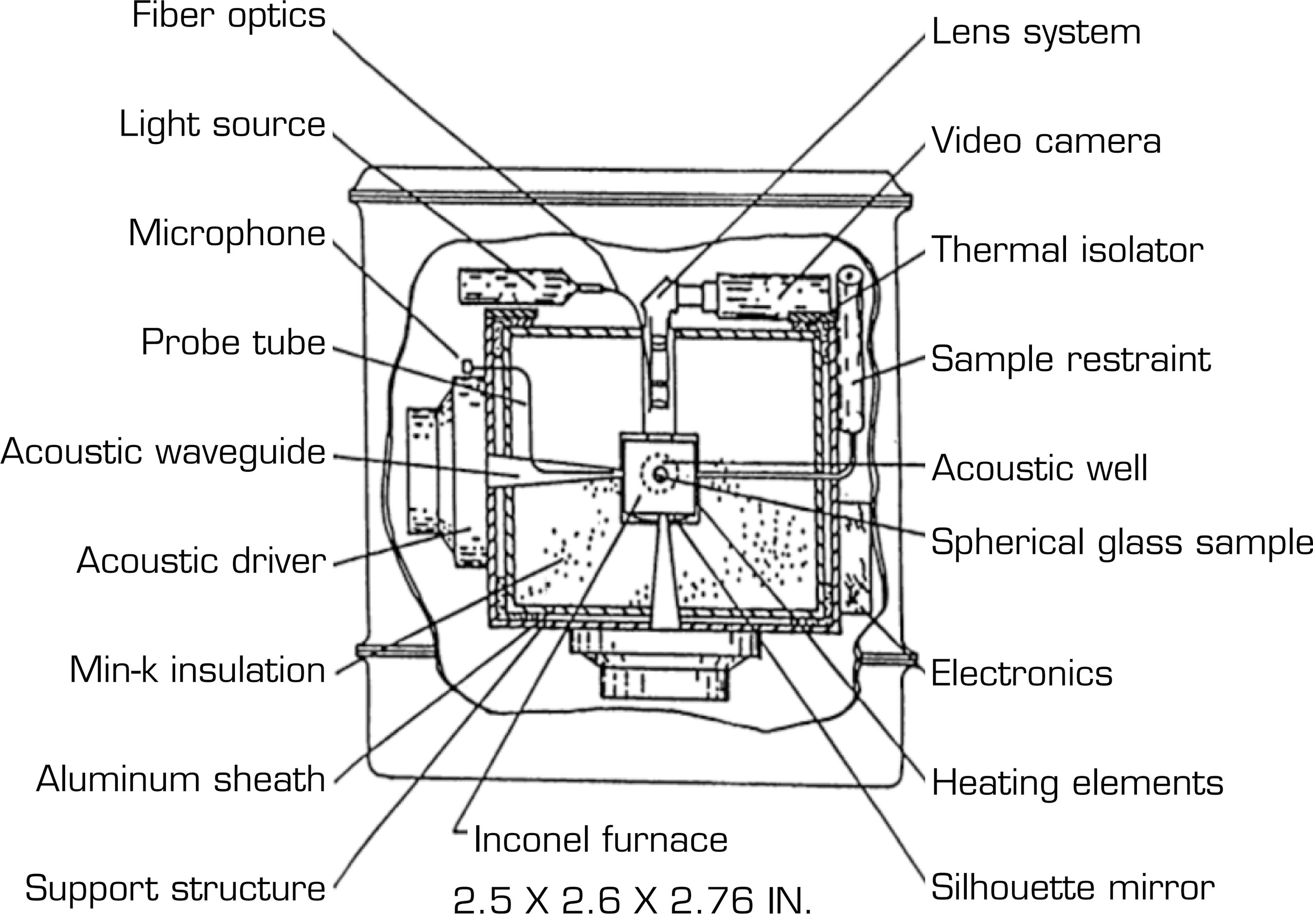
In developing the design proposal, two previously reported models will be considered. The first is that of Elleman et al. (1988), who designed an acoustic levitation chamber consisting of a three-axis acoustic positioner arranged along three orthogonal walls of the chamber. The sound waves generated by this system produced a standing force used to position the sample at the center of the chamber (Fig. 1). This chamber was intended to be tested during the STS 41-B flight aboard NASA’s Challenger vehicle; unfortunately, no useful data could be obtained due to instrument malfunction.

The second design to be considered is that proposed by Marzo et al. (2017), who introduced the “TinyLev” design, a single-axis, multi-emitter acoustic levitator. For the present project, however, the “BigLev” design – a variation of TinyLev capable of levitating larger solid objects up to 5 g·cm3 – offers greater applicability. The design proposed here therefore results from a combination of both approaches.
Justification
Experimental rocketry has become a valuable tool for conducting scientific tests in fields such as meteorology, telecommunications, and medicine. However, the potential of integrating acoustic levitation phenomena into this context has been scarcely explored. This research aims to demonstrate the feasibility of maintaining particles in suspension through acoustic levitation during the different phases of an experimental rocket flight. If the results prove favorable, this approach could open new possibilities for the contactless manipulation of materials or samples in dynamic environments. In addition, the project seeks to foster the interest of the academic community at the faculty of engineering in the interdisciplinary study of experimental rocketry and acoustic levitation.
Conceptual framework
Concepts related to acoustic levitation
Understanding acoustic levitation requires consideration of several key concepts. First, frequency, which Sierra Tabla (2011) defines as the number of waves occurring in one second. According to the International System of Units, which is used by most countries worldwide, frequency must be measured in hertz (Hz). One hertz corresponds to the frequency of a periodic event that repeats once per second, a unit also understood as cycles per second. Second, the concept of standing waves must be addressed. As Jiménez-Carballo (2018) explains, standing waves arise from the interference of two waves of the same nature and with identical physical characteristics traveling in opposite directions – in other words, they result from the superposition of an incident wave and a reflected wave. In standing waves, certain points known as nodes remain motionless. The third concept to consider is the Gor’kov potential, which, according to Barmatz and Collas (1985), is defined as the levitational stability of a particle at a specific position within an acoustic field – that is, the effectiveness of the acoustic forces at that point in allowing a particle to remain levitating despite weak random perturbations. The gradient of the Gor’kov potential can be used to calculate the force exerted on a sphere by a complex pressure field, as previously formulated by Marzo et al. (2017).
where V is the volume of the spherical particle, ω is the frequency of the emitted waves, ρ is the density, and c is the speed of sound (with subscripts 0 and p referring to the host medium and the particle material, respectively). p denotes the complex pressure and px its derivative with respect to x.
Acoustic levitation
Once these fundamental concepts have been established, it is possible to examine acoustic levitation itself, which can take different forms to suspend a particle in air using ultrasonic frequencies. Existing devices can be classified according to their geometry, the type of emitters employed, and the patterns they generate. Among these, the standing-wave method is currently the most common. As Bustillos Rava (2022) explains, this method establishes a stationary pressure wave with nodes that act as acoustic traps capable of capturing particles smaller than the generated wavelength.
Resonant and non-resonant levitators
When dealing with standing-wave levitators, two main categories can be distinguished: resonant and non-resonant levitators.
Resonant levitator
If the objective is to establish a standing wave, resonance is a factor in achieving high intensities in the acoustic field by maximizing the amplitude of the pressure wave. The waves generated by an emitter are reflected by any nearby reflective surface. In the case of a single-axis acoustic levitator consisting of an emitter and a reflector, the resulting wave between the two is a combination of the emitted and reflected waves. To achieve resonance, it is essential to maintain a specific distance between the emitter and the reflector. In the context of a standing wave, this distance must be an integer multiple of half the wavelength. The design of the emitter and reflector geometry plays a crucial role in improving the efficiency of a resonant levitator. It has been shown that certain radii of curvature in a concave reflector, rather than a flat one, generate greater acoustic force, making it possible to capture denser objects.
Non-resonant levitator
Unlike resonant levitators, non-resonant levitators do not rely on resonance to levitate objects. In this type of levitator, there is no attempt to establish a resonance condition between the emitter and the reflector, which makes them more versatile in terms of the distance between these two elements.
Instead of relying on a specific distance relationship to create a standing wave, non-resonant acoustic levitators use multiple transducers to generate in-phase sound waves that interact and form high-pressure zones. These high-pressure zones support the object and keep it levitating.
Rockets used in experimental rocketry can vary in size, from small water-powered models to larger rockets powered by solid or liquid-fuel engines (Robayo-Salazar et al. 2021).
The objectives of experimental rocketry may include measuring altitudes, observing atmospheric phenomena, collecting meteorological data, experimenting with scientific payloads, or testing new propulsion designs and technologies. Experimental rocketry enthusiasts and professionals often seek to better understand the physical principles governing rocket flight, as well as to develop practical skills in design and construction.
The design and construction of rockets to transport acoustic levitators to altitudes of 3 km are a challenge that combines scientific precision and advanced aerospace engineering.
The main purpose of this project is to take the acoustic levitator to significant altitudes to conduct experiments that take advantage of the unique conditions during flight at different altitudes.
METHODOLOGY
As part of the research, the design and optimization of the acoustic levitator were addressed, following a structured methodology that allowed its feasibility to be evaluated before conducting tests under real flight conditions. The comprehensive approach adopted combined acoustic theory with experimental methods and was organized into several key phases, ensuring the solid and systematic development of the system.
Phases of the methodology
The development of the acoustic levitator proposed for integration into an experimental rocket vehicle was carried out using a structured methodological approach that allowed for the evaluation of both the theoretical and experimental feasibility of the system prior to its implementation in real flight conditions. This comprehensive approach combined principles of advanced acoustic theory with experimental methods, facilitating the optimization and validation of the design at each stage of the process. The methodology adopted was organized into several sequential phases, each focusing on a specific aspect of the design and improvement of the acoustic levitator, thus ensuring a robust and controlled development of the system.
The first phase consisted of a detailed review of the fundamental principles of acoustic levitation, as well as an analysis of previous studies related to similar applications, especially in controlled environments such as research laboratories. During this initial phase, the key operating parameters of the system were defined, such as the ultrasonic frequencies required to generate static acoustic waves, and the operating theory on which the levitator design would be based was established. Based on this theoretical framework, it was determined that the design needed to be adapted to the specific limitations of the experimental rocket’s payload bay, considering factors such as available size and real flight conditions.
The second phase of the process focused on the conceptual design of the acoustic levitator. At this stage, modeling and simulation tools were used to generate a digital prototype that would allow the behavior of the system under variable conditions to be predicted. Acoustic resonance analyses were carried out, and the design of the ultrasonic transducers, which are responsible for generating the acoustic waves that keep the particles suspended in the air, was optimized. Numerical simulation made it possible to evaluate the distribution of acoustic pressure in space and make adjustments to maximize the efficiency and stability of the levitator.
Once the preliminary design was complete, the third phase began: the construction and testing of the small-scale prototype. During this stage, tests were carried out under controlled laboratory conditions, where the levitator’s ability to suspend and manipulate small-scale particles was evaluated. In addition, key aspects such as the system’s ability to adapt to different particle sizes and its performance as a function of variations in the frequency and amplitude of the ultrasonic waves were verified.
The fourth phase is currently underway and consists of integrating the acoustic levitator with the experimental rocket vehicle. In this phase, field tests will be carried out, where the system will be subjected to simulated flight conditions, including pre-launch, launch, and descent of the vehicle. These tests are intended to evaluate the levitator’s ability to maintain the stability of suspended particles throughout the entire flight cycle, evaluating both its acoustic performance and its reliability under dynamic and high-acceleration conditions.
RESULTS
Analysis of simulated flight conditions for AKBAL-II
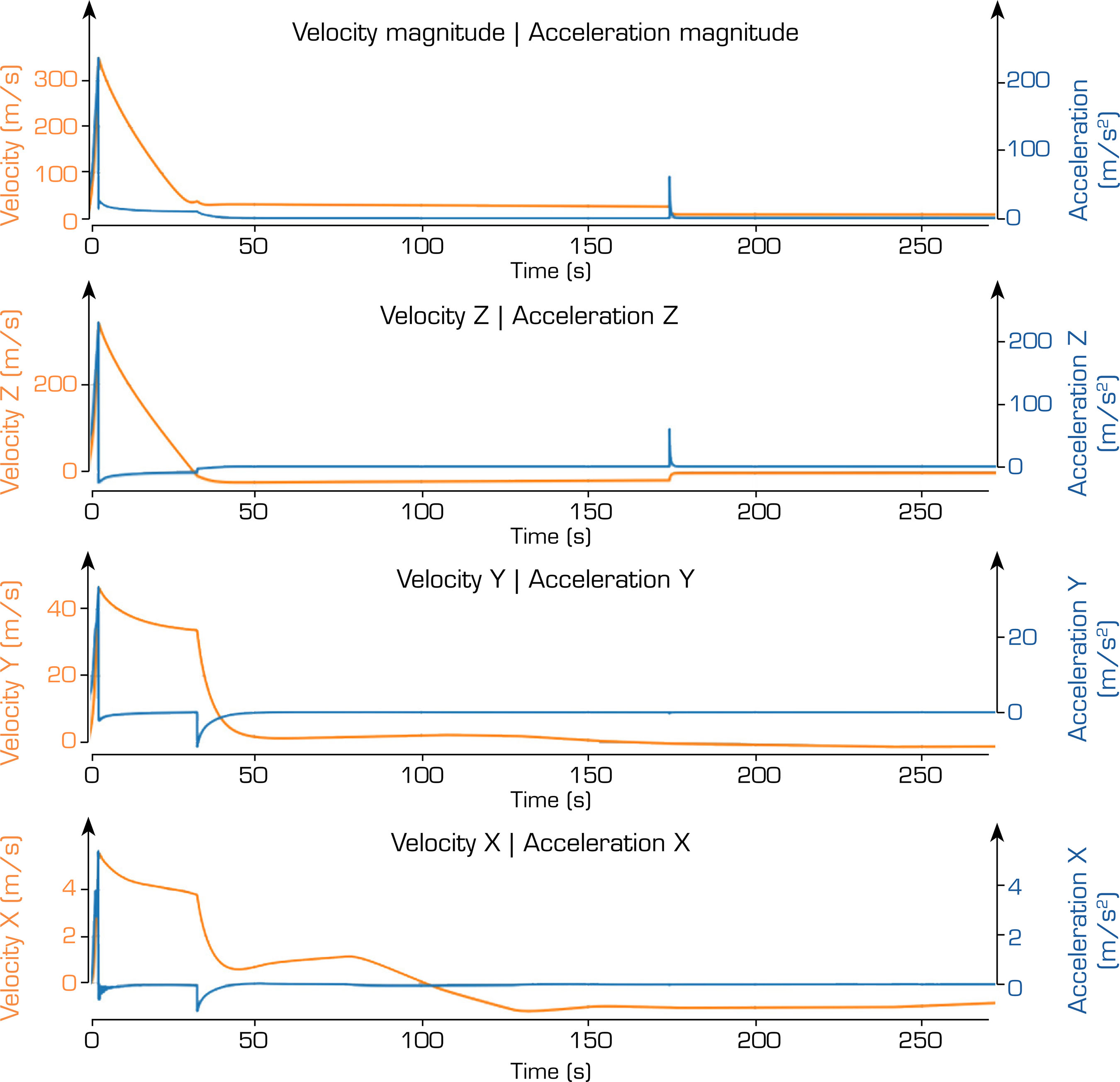
To evaluate the feasibility of the acoustic levitator under the dynamic flight conditions of the AKBAL-II rocket, simulations were performed using the RocketPy tool developed by Colasurdo et al. (2023), which models the behavior of experimental rockets based on aerodynamic, environmental, and propulsion parameters. The simulation was configured for a launch from Laguna de Sayula (19.99235° N, -103.56466° W, elevation 1824.8 m ASL) with an AKBAL-II rocket equipped with an N3930 solid motor (total impulse: 13208.014 Ns, burn time: 3.33 s). Key results of the simulation include:
Maximum acceleration: 234.41 m·s² (23.903 G) at 3.3 s during engine ignition, representing the most extreme condition for the acoustic levitator.
Maximum altitude: 6424.548 m ASL (4599.729 m AGL), reached at 31.378 s (apogee).
Atmospheric pressure: varies from 82.35 kPa at the surface to approximately 60 kPa at maximum altitude, according to the Global Forecast System (GFS) atmospheric model.
Estimated vibrations: based on the rocket design and previous experimental rocket studies (Robayo-Salazar et al. 2021), vibrations in the range of 10-100 Hz with amplitudes of up to 0.5 mm were assumed during ascent.
Parachute events: drogue parachute ejection at 31.381 s (4588.867 m above ground level [AGL]) and main parachute ejection at 172.924 s (763.066 m AGL), generating dynamic changes in the rocket’s orientation and velocity.
Total flight time: 272.71 s, from launch to impact.
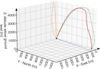
The simulated altitude and vertical acceleration profiles are presented in Figs. 2 and 3, respectively, while the main flight conditions are summarized in Table 1.

Derived design requirements from AKBAL-II simulated flight conditions
The simulated flight conditions were used to define preliminary design requirements for future validation of the acoustic levitation payload. These requirements do not represent completed flight qualification tests; instead, they establish the mechanical, environmental, and operational conditions that the prototype must satisfy before in-flight implementation. Table 2 summarizes the main design requirements derived from the AKBAL-II numerical simulation.
Acoustic levitation system design
A system was developed using ultrasonic waves to create an acoustic field that would allow particles to be suspended in real time. This phase involved redesigning the Mk3 proposal by Argyri et al. (2024), while drawing on the TinyLev configuration reported by Marzo et al. (2017) (Fig. 4), using 36 transducers at 40 kHz distributed across two surfaces.

The redesign consists of adapting this model so it can be transported in the payload bay of the AKBAL-II, which requires adapting the length of the levitator to the length of the bay, isolating the levitation axis using transparent acrylic, and adopting the idea of Aquino et al. (2024), so that the outside air during flight does not interfere with the levitation of the particle. In addition, to analyze the behavior of the particle during flight, it is necessary to incorporate a camera that is capable of seeing inside the levitation chamber by focusing directly on the levitation axis. The images will be stored in real time on a built-in micro-SD card in the circuit so that, once the system is recovered, the behavior can be analyzed. Transmitting the images in real time to the ground station is not considered to avoid overloading the flight system’s transmission media, to prevent interference, and to save battery power during flight, which in turn reduces the weight of the payload.
Prototype configuration and laboratory validation procedure
The prototype was configured as a compact single-axis, non-resonant acoustic levitator designed to fit within the payload bay constraints of the AKBAL-II experimental rocket. The acoustic system consisted of two opposed arrays, each containing 18 commercial ultrasonic transducers, for a total of 36 transducers. Each transducer had a diameter of 10 mm and operated at a fixed frequency of 40 kHz. The external diameter of the levitator structure was 50 mm, with a transducer distribution radius of 21 mm. The separation between the two arrays was defined according to the geometric constraints of the levitation chamber and the expected position of the acoustic node. In the current prototype, this separation was kept equal to the nominal Mk3 array spacing proposed by Argyri et al. (2024), with an approximate distance of 30 mm between the facing surfaces of the upper and lower arrays.
The control electronics were placed in a dedicated electronics bay attached to the levitation chamber. This bay included a microcontroller, an H-bridge driver for transducer excitation, a 12 V DC regulated power supply, a camera module, a micro-SD card reader module, and the required wiring and battery connections. The camera was oriented toward the levitation axis to record the behavior of the suspended particle during testing. Video transmission to the ground station was not considered in this phase in order to reduce power consumption, avoid telemetry interference, and minimize system complexity. Instead, visual data were stored locally on the micro-SD card for post-test analysis.
The acoustic cavity was enclosed using a transparent acrylic cylinder. This component was incorporated to isolate the levitation axis from external airflow and to allow visual inspection of the suspended particle. Coupling elements were included to secure the acrylic cylinder to the upper and lower assemblies and to improve the sealing of the chamber. At this stage, the chamber was evaluated under laboratory conditions and was not subjected to flight-induced acceleration, vibration-table testing, or pressure-chamber testing.
Laboratory validation was conducted under static room conditions. The procedure consisted of activating the acoustic field, placing solid particles near the levitation region, and observing whether stable suspension was achieved. Solid particles of approximately 2.0 mm in diameter and approximately 5 mg in mass were used during the preliminary tests. The longest continuous levitation period observed was 25 minutes, after which the system was turned off to prevent overheating. Since repeated statistical trials were not performed at this stage, the reported levitation time should be interpreted as a maximum observed value rather than an average stability metric.
The validation procedure was therefore limited to verifying particle suspension, visual stability under static conditions, basic operation of the control electronics, and compatibility of the prototype with the spatial constraints of the payload bay. Dynamic validation under representative flight loads remains future work.
Optimization of acoustic parameters
This phase included laboratory testing to adjust critical system variables such as wave frequency, particle density, and applied voltage. Indicators such as stability time, energy consumption, and response to external changes were monitored. Table 3 summarizes the key technical parameters of the acoustic levitation prototype evaluated under laboratory conditions.
Laboratory validation indicators
During the preliminary laboratory validation stage, the prototype was evaluated under static conditions to verify particle suspension and basic system stability. Since this stage did not include a statistically controlled experimental campaign, the indicators reported below should be interpreted as preliminary laboratory observations. Table 4 summarizes the indicators obtained during the current validation stage and identifies the measurements that remain pending for future work.
The longest continuous levitation time observed during laboratory testing was 25 minutes. The test was interrupted as a precautionary measure when the electronics reached approximately 70 °C in order to prevent overheating. Therefore, this value is reported as the maximum observed levitation time rather than as an average performance metric. Energy consumption, position deviation, stability-loss rate, and repeatability were not quantified during this stage. These parameters will be evaluated in future work through repeated trials, electrical measurements, thermal monitoring, and video-based particle tracking.
Analysis and development of the prototype
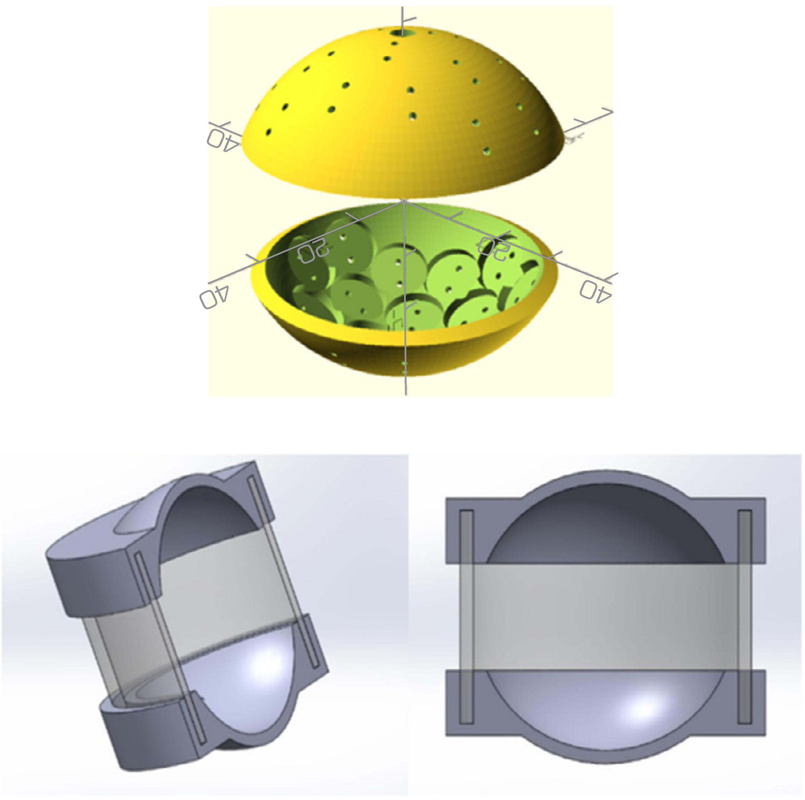
The 3D model in Fig. 5 represents the proposed design prior to 3D printing. The model shows the main components of the proposed levitator. First, the upper assembly and the lower assembly, each with 18 slots for transducer installation. The design, distribution, and spacing between transducers were maintained as proposed by Argyri et al. (2024), so as not to modify the behavior of the levitation axis. In addition, it can be seen that couplers are to be used to secure the acrylic cylinder and, at the same time, create an airtight seal.
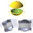
Secondly, there is the electronics bay, which contains everything related to the circuit that will control the levitator, including a microcontroller, an H-bridge, a camera, a micro-SD card reader module, and batteries.
Analysis of experimental/computational procedures
Phase 1 – Prototype development
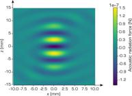
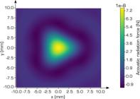
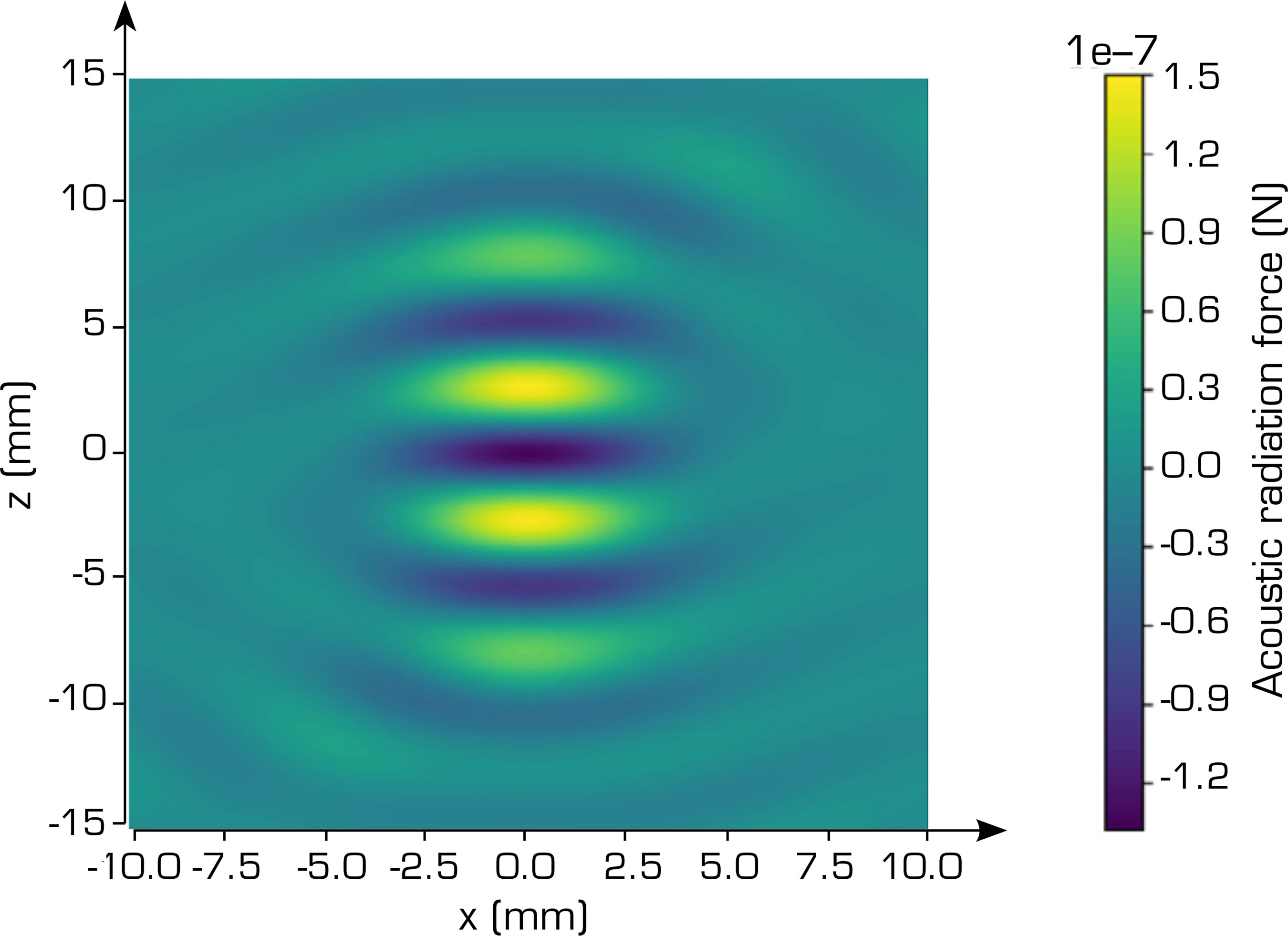
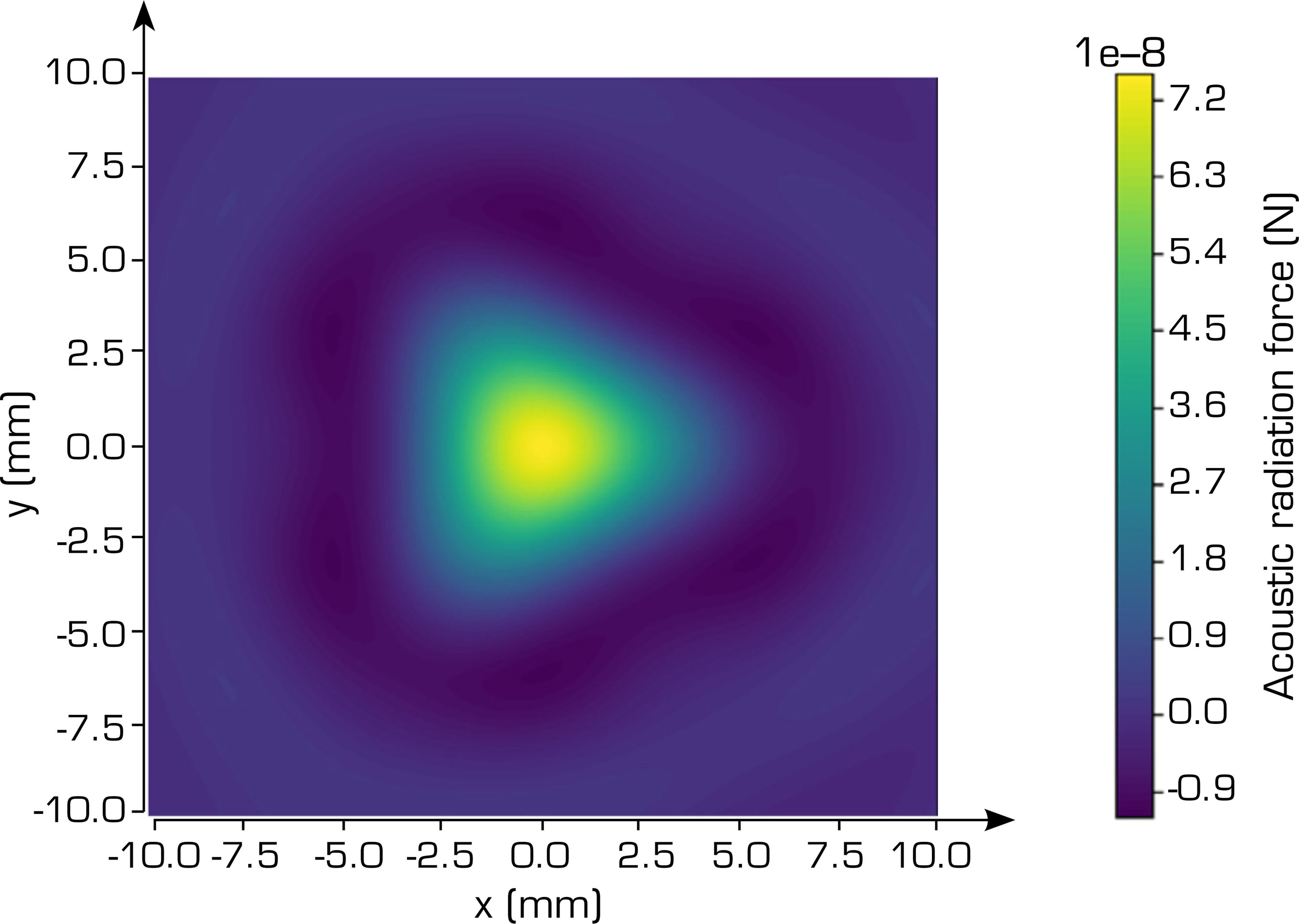
The Omnilev acoustic levitator simulator developed by Andersson and Kellnberger (2022) was used to obtain various graphs that illustrate the levitator’s performance under different operating conditions. The resulting pressure-field distribution and Gor’kov-potential maps are presented in Fig. 6–8, allowing the effectiveness of the system to be analyzed in relation to the operating frequency, transducer arrangement, and predicted particle stability. The proposed prototype was a single-axis non-resonant levitator with the following characteristics:

-
Number of transducers: 36
-
Operating frequency: 40 kHz
-
Transducer size: 10 mm
-
Total diameter: 50 mm
-
Radius diameter: 21 mm
The results obtained provide valuable information to optimize the design of the acoustic levitator and its future implementation in practical experiments.
This phase includes the design of the electronics bay, which will house everything related to the circuit that will control the levitator, including a microcontroller, a camera, a micro-SD card reader module, and batteries.
Phase 2 – Testing and validation
Preliminary validation tests were carried out to verify the basic operation of the acoustic levitation prototype under controlled laboratory conditions. At this stage, the tests focused on confirming particle suspension, assessing the functionality of the acoustic cavity, verifying the airtight seal of the acrylic cylinder, and checking the operation of the electronic and visual monitoring systems.
The acrylic cylinder was evaluated to verify the effectiveness of the sealing system and to ensure that the chamber maintained its shape and functionality during static laboratory operation. This validation was limited to laboratory conditions; therefore, the chamber has not yet been subjected to representative launch acceleration, vibration loads, or reduced-pressure conditions.
Test iterations were conducted using different particle sizes. Based on the results obtained so far, the solid particles used during laboratory validation had an approximate diameter of 2.0 mm and an approximate mass of 5 mg. For liquid particles, the preliminary tested droplet volume was in the range of 3 to 5 µL. These values should be interpreted as preliminary laboratory parameters rather than optimized limits for in-flight operation.
The electronic system was also tested to verify the basic operation of the levitator, including the activation of the transducers, the response of the control circuit, and the functionality of the camera and micro-SD recording system. During these tests, the longest continuous levitation period observed was 25 minutes. The test was interrupted when the electronics reached approximately 70 °C in order to prevent overheating.
The validation performed in this phase confirms preliminary particle suspension under static laboratory conditions. However, position deviation, stability-loss rate, energy consumption, voltage sensitivity, repeatability, and detailed thermal behavior were not quantified during this stage. These parameters remain pending for future validation through repeated trials, video-based particle tracking, electrical characterization, thermal monitoring, vibration-table testing, pressure-chamber testing, and in-flight experiments.
DISCUSSION
The construction and proposed integration of an acoustic levitator into an experimental rocket represent a convergence between acoustic manipulation technologies and aerospace system design. While acoustic levitation has been extensively studied in controlled laboratory environments, its adaptation to compact, structurally constrained aerospace payloads presents new design and operational challenges. In this context, the present work contributes by tailoring a non-resonant multi-emitter configuration to the geometric and mechanical limitations of an experimental rocket, thereby extending existing levitation concepts toward dynamic aerospace applications.
Previous studies, such as those by Marzo et al. (2017) with TinyLev and Argyri et al. (2024) with high-performance acoustic levitators, have demonstrated that it is possible to construct a stable acoustic field that is precise enough to hold suspended particles with submillimeter accuracy under controlled laboratory conditions. However, these systems were developed under controlled and stable conditions that are completely different from the dynamic and aggressive processes involved in the launch and flight of an experimental rocket. The current approach sets a completely new goal: to adapt these technologies to an environment of high acceleration, structural vibration, and atmospheric pressure changes without losing functionality or acoustic stability.
Although simultaneous levitation of solid and liquid particles has been demonstrated under laboratory conditions, their behavior under high acceleration and vibration loads remains to be experimentally validated. Numerical simulations of the AKBAL-II rocket provide insight into the magnitude of expected accelerations (up to 23.9 G), atmospheric pressure variations, and transient vibration conditions. These simulations serve to define the operational envelope for future experimental campaigns rather than to confirm in-flight functionality.
Potential applications of this technology may include contactless manipulation of small samples during suborbital experimental missions, studies involving particle or droplet behavior under changing atmospheric conditions, and preliminary handling of contamination-sensitive materials. However, these applications remain conceptual at this stage and should not be interpreted as demonstrated capabilities of the current prototype. Their implementation would require additional validation under vibration, acceleration, pressure variation, thermal loading, and extended operational conditions.
Additionally, the use of an embedded computer system such as the ESP32 to control the levitator during flight stands out for its simplicity, low cost, and portability. This approach contrasts with projects such as that of Chen et al. (2024). Although they demonstrate the stability of levitated droplets, they do so from static platforms and with more robust controllers, whereas the proposed configuration prioritizes portability and structural integration. Nevertheless, robustness under sustained vibration, thermal variation, and mechanical shock must be verified through dedicated environmental testing.
Regarding practical implications, the proposed prototype may serve as a testbed for student-led aerospace experimentation, enabling preliminary levitation experiments within suborbital research platforms. However, its reliability in dynamic flight environments remains subject to further experimental verification.
Finally, several limitations must be acknowledged. The sensitivity of the acoustic field to vibration, the potential deformation of the levitation cavity under acceleration, and the constraints of onboard energy storage represent significant technical challenges. Addressing these factors through vibration-table testing, pressure-chamber validation, and flight campaigns will be essential to determine the true operational viability of the system.
In summary, this study establishes a laboratory-validated acoustic levitation prototype tailored to an experimental rocket configuration and defines a structured pathway for future validation under real flight conditions. The results contribute to expanding the conceptual integration of acoustic manipulation technologies within aerospace research while maintaining a clear distinction between demonstrated performance and projected applications.
CONCLUSION
This research focused on the design and optimization of an acoustic levitator and achieved preliminary validation under controlled laboratory conditions. Through a methodological approach combining simulation, modeling, and laboratory testing, a functional prototype was developed and evaluated for preliminary particle suspension using ultrasonic waves under static conditions. These results provide a basis for future validation in more complex aerospace environments.
The prototype was designed for future integration into the AKBAL-II experimental rocket and was configured according to the spatial constraints of the payload bay. Initial laboratory tests confirmed particle suspension under static conditions and basic compatibility with the proposed chamber configuration. However, full validation throughout the flight cycle has not yet been experimentally performed, and in-flight testing remains part of future work.
The results obtained so far support the preliminary feasibility of the proposed acoustic levitation system at the prototype level. Nevertheless, its operation under representative rocket-flight conditions requires further validation, including vibration-table testing, pressure-chamber testing, thermal monitoring, electrical characterization, repeatability analysis, and future flight experiments.
ACKNOWLEDGEMENTS
The authors acknowledge the Sociedad Aeroespacial de la Facultad de Ingeniería at the Universidad Autónoma del Estado de México for its technical collaboration and support during the design, development, and preliminary laboratory evaluation of the acoustic levitation prototype. The authors also acknowledge the academic guidance, supervision, and technical contributions that supported the development of this research.
-
Peer Review History:
Single Blind Peer Review.
-
FUNDING
Not applicable.
-
DECLARATION OF USE OF ARTIFICIAL INTELLIGENCE TOOLS
Generative artificial intelligence tools were used to support language revision, translation, and editorial refinement during manuscript preparation. These tools were not used to generate, analyze, or interpret experimental data, perform simulations, produce research results, or make scientific decisions. All outputs were critically reviewed, verified, and revised by the authors, who assume full responsibility for the accuracy, originality, and integrity of the manuscript.
DATA AVAILABILITY STATEMENT
The simulation parameters and main data supporting the findings of this study are included in the manuscript. Additional laboratory notes and prototype characterization data are available from the corresponding author upon reasonable request.
REFERENCES
-
Andersson C, Kellnberger R (2022) Levitate: Python implementation of acoustic levitation and related topics [software]. GitHub. [accessed Jun 01 2025]. https://github.com/AppliedAcousticsChalmers/levitate
» https://github.com/AppliedAcousticsChalmers/levitate -
Aquino RCD, Vargas KEC, Rios SSS, Milián JR, Roman-Gonzalez A (2024) Can acoustic levitation simulate microgravity in fluids? Paper presented 2024 International Astronautical Congress. International Astronautical Federation; Milan, Italy. [accessed Sep 20 2025]. https://www.researchgate.net/publication/385213505_Can_Acoustic_Levitation_Simulate_Microgravity_in_Fluids
» https://www.researchgate.net/publication/385213505_Can_Acoustic_Levitation_Simulate_Microgravity_in_Fluids -
Argyri SM, Andersson C, Paillet N, Evenäs L, Ahrens J, Marzo A, Bordes R (2024) Customized and high-performing acoustic levitators for contact-free experiments. J Sci Adv Mater Dev 9(3):100720. https://doi.org/10.1016/j.jsamd.2024.100720
» https://doi.org/10.1016/j.jsamd.2024.100720 -
Barmatz M, Collas P (1985) Acoustic radiation potential on a sphere in plane, cylindrical, and spherical standing wave fields. J Acoust Soc Am 77(3):928-945. https://doi.org/10.1121/1.392061
» https://doi.org/10.1121/1.392061 -
Bücks K, Müller H (1933) Über einige Beobachtungen an schwingenden Piezoquarzen und ihrem Schallfeld. Z Phys 84: 75-86. https://doi.org/10.1007/BF01330275
» https://doi.org/10.1007/BF01330275 -
Bustillos Rava JF (2022) Levitación acústica: principios básicos del funcionamiento de un levitador acústico (undergraduate thesis). Córdoba: Universidad Nacional de Córdoba. In Spanish. [accessed Aug 15 2025]. http://hdl.handle.net/11086/29648
» http://hdl.handle.net/11086/29648 -
Chen H, Hong Z, Zang D (2024) New insights into suspended drops: when soft matter meets acoustic levitation. Droplet 3:e95. https://doi.org/10.1002/dro2.95
» https://doi.org/10.1002/dro2.95 -
Colasurdo L, Vieira G, Osorio A, Rizzi T, Ciminelli D, Cavalcanti P, Meireles M (2023) RocketPy: next generation High-Power Rocketry 6-DOF Trajectory Simulation [software]. GitHub. [accessed Jul 03 2025 ]. https://github.com/RocketPy-Team/RocketPy
» https://github.com/RocketPy-Team/RocketPy -
Elleman DD, Wang TG, Barmatz M (1988) Acoustic containerless experiment system: a non-contact surface tension measurement. In: Microgravity science and applications flight programs: January-March 1987, selected papers. Vol. 2. Washington (DC): National Aeronautics and Space Administration; p. 557-567. [accessed Aug 12 2025]. https://books.google.com.br/books?hl=pt-BR&lr=&id=VfwOAQAAMAAJ&oi=fnd&pg=PA557&dq=Elleman+DD,+Wang+TG,+Barmatz+M+(1988)+Acoustic+containerless+experiment+system:+a+non-contact+surface+tension+measurement.+In:+Microgravity+science+and+applications+flight+programs:+January-March+1987,+selected+papers.+Vol.+2.+&ots=kL0K8IQkbw&sig=mb7jzBfj4HQQ14quv7iVVIUfTFY#v=onepage&q&f=false
» https://books.google.com.br/books?hl=pt-BR&lr=&id=VfwOAQAAMAAJ&oi=fnd&pg=PA557&dq=Elleman+DD,+Wang+TG,+Barmatz+M+(1988)+Acoustic+containerless+experiment+system:+a+non-contact+surface+tension+measurement.+In:+Microgravity+science+and+applications+flight+programs:+January-March+1987,+selected+papers.+Vol.+2.+&ots=kL0K8IQkbw&sig=mb7jzBfj4HQQ14quv7iVVIUfTFY#v=onepage&q&f=false -
Jiménez-Carballo CA (2018) Ondas estacionarias. Cartago (Costa Rica): Instituto Tecnológico de Costa Rica [accessed Jul 02 2025]. https://hdl.handle.net/2238/10190
» https://hdl.handle.net/2238/10190 -
Marzo A, Barnes A, Drinkwater BW (2017) TinyLev: a multi-emitter single-axis acoustic levitator. Rev Sci Instrum 88(8):085105. https://doi.org/10.1063/1.4989995
» https://doi.org/10.1063/1.4989995 -
Pajander JP, Matero S, Sloth J (2015) Raman mapping of mannitol/lysozyme particles produced via spray drying and single droplet drying. Pharm Res 32:1993-2002. https://doi.org/10.1007/s11095-014-1592-z
» https://doi.org/10.1007/s11095-014-1592-z -
Robayo-Salazar RA, Portocarrero-Hermann J, Meneses-Suta J, Salgado-Díaz J, Martínez-Riaño S, Delgado F, Gómez-Ruge A (2021). Diseño, construcción y prueba estática experimental de un motor-cohete de combustible sólido. Rev UIS Ing 20(2):97-108. https://doi.org/10.18273/revuin.v20n2-2021009
» https://doi.org/10.18273/revuin.v20n2-2021009 -
Sierra Tabla MA (2011) Sistema caracterizador de equipos de audio (SCEA) (undergraduate thesis). Ciudad de México: Universidad Nacional Autónoma de México. [accessed Jul 01 2025]. https://repositorio.unam.mx/contenidos/sistema-caracterizador-de-equipos-de-audio-scea-3507091?c=rvz6B8&d=false&q=*:*&i=10&v=1&t=search_0&as=0
» https://repositorio.unam.mx/contenidos/sistema-caracterizador-de-equipos-de-audio-scea-3507091?c=rvz6B8&d=false&q=*:*&i=10&v=1&t=search_0&as=0 -
Vasileiou T, Foresti D, Bayram A, Poulikakos D, Ferrari A (2016) Toward contactless biology: Acoustophoretic DNA transfection. Sci Rep 6: 20023. https://doi.org/10.1038/srep20023
» https://doi.org/10.1038/srep20023
Edited by
-
Section editor:
Bert Pluymers https://orcid.org/0000-0002-7996-8350

 Source: Adapted from
  Source: Elaborated by the authors.
 Source: Elaborated by the authors.
 Source: Retrieved from
  Source: Elaborated by the authors.
 Source: Elaborated by the authors.
 Source: Elaborated by the authors.
 Source: Elaborated by the authors.