 Shape-Stabilized NaNO3 Phase Change Materials Supported by CO2-Mineralized Basic Oxygen Furnace Slag for Photothermal Heat Storage
Abstract
NaNO3 shape-stabilized composite phase change materials (PCMs) supported by CO2 mineralized basic oxygen furnace (BOF) slag were developed for photothermal heat storage. The effects of slag mineralization degree and NaNO3 loading on structure, phase transition behavior, thermal stability, thermal conductivity, and cycling stability were systematically investigated. CO2 mineralization converted active Ca/Mg-bearing phases in BOF slag into carbonate phases, increasing the weight gain from 9.37 to 17.45% as mineralization time increased from 30 to 120 min. Among the mineralized samples, CSS-60 provided the most favorable balance between mineralization degree and accessible porosity. Using CSS-60 as the supporting skeleton, the composite PCMs showed good shape stability. The melting enthalpies of OPT-N40, OPT-N50, and OPT-N60 were 67.43, 83.22, and 97.38 J g-1, respectively. Compared with pure NaNO3, the composites exhibited improved thermal stability and higher thermal conductivity. After 300 thermal cycles, all samples maintained good thermal cycling stability, with shifts in onset and peak temperatures below 0.5 °C and enthalpy decay below 5%. OPT-N50 showed the best overall performance. These results indicate that CO2-mineralized BOF slag is a promising low-cost and low-carbon supporting matrix for NaNO3-based medium-temperature photothermal heat storage.
Keywords:
basic oxygen furnace slag; CO2 mineralization; shape-stabilized PCMs; photothermal storage; cycling stability
Introduction
Under the ongoing low-carbon transition of energy systems and the increasing penetration of renewable energy, thermal energy storage has become a key enabling technology for improving solar thermal utilization, recovering industrial waste heat, and enhancing the operational flexibility of integrated heat-power systems.1,2 Compared to sensible heat storage, latent heat storage provides higher energy storage density within a narrower temperature interval. This makes it particularly attractive for mediumand high-temperature applications.3 In concentrated solar power systems, phase change thermal storage is widely regarded as a promising complement to conventional two-tank molten-salt sensible heat storage and can provide a material basis for latent heat storage units and integrated energy systems coupled with heat supply scenarios.3,4
Among inorganic salts for medium-temperature latent heat storage, NaNO3 is one of the most representative candidates because of its suitable phase transition temperature, low cost, good thermochemical stability, and manageable corrosiveness.5 Previous studies6,7 have shown that loading NaNO3 into diatomite, porous ceramics, or composite skeletons can effectively suppress molten salt leakage and improve structural integrity, thereby enabling shape-stabilized operation. Nevertheless, NaNO3-based systems still suffer from high melt fluidity, limited thermal conductivity, obvious volume variation during phase transition, and insufficient structural stability after repeated thermal cycling, which restrict their direct application in modular and engineering-scale thermal storage units.5-7
Shape-stabilized composite phase change materials (PCMs) generally rely on porous skeletons to physically confine molten phase change components, thereby mitigating leakage and improving service stability. In this context, industrial solid wastes have gradually emerged as attractive skeleton sources owing to their wide availability, low cost, and urgent need for valorization.8,9 For slag-based supporting systems, a variety of technical routes have been reported, including steel slag porous ceramics loaded with NaNO3, direct steel slag/carbide slag skeletons, metallurgical slag-derived porous ceramics impregnated with solar salts, and modified slag-based porous composite structures.10-12 These studies suggest that steel slag can serve not only as a low-cost supporting phase but also as a contributor to structural reinforcement, heat transfer enhancement, and partial sensible heat storage, making it a promising matrix for composite PCMs.13,14
Basic oxygen furnace (BOF) slag is a bulk industrial byproduct generated during steelmaking. It is typically rich in Ca, Mg, Fe, and Si, and often contains active mineral phases as well as unstable free CaO and MgO. This composition gives BOF slag both considerable valorization potential and inherent concerns regarding volume stability and structural reliability.15,16 In recent years, growing evidence has shown that CO2 mineralization/carbonation can convert active Ca/Mg-bearing phases in steel slag into more stable carbonate phases, thereby simultaneously enabling CO2 sequestration, structural densification, and improved downstream utilization performance.17-20 Compared to untreated slag, CO2-mineralized BOF slag is therefore expected to serve as a low-cost, low-carbon, and structurally stable skeleton precursor for shape-stabilized composite PCMs.
Although rapid progress has been made in slag-based PCM systems, most existing studies have focused on KNO3/slag composites, metallurgical slag-derived porous ceramics supporting NaNO3, modified diatomite-based NaNO3 systems, and more general strategies for inorganic salt shape-stabilized composite PCMs.21-24 Meanwhile, molten salt and eutectic salt phase change systems for concentrated solar power still face key bottlenecks in leakage suppression, heat transfer enhancement, structural stability, and scalable fabrication.2,25 In contrast, studies on directly using CO2-mineralized BOF slag as a supporting skeleton for NaNO3, along with systematic evaluations of the effects of mineralization on encapsulation behavior, thermal storage performance, thermal stability, and cycling stability remain limited.
Therefore, this study employed BOF slag as the starting material and first subjected it to CO2 mineralization to obtain supporting skeletons with different mineralization degrees. NaNO3 was then introduced as the phase change component, and shape-stabilized composite PCMs were prepared by a cold pressing-heat treatment route. Particular attention was paid to the effects of CO2 mineralization on slag phase composition, pore accessibility, encapsulation behavior, phase transition performance, thermal conductivity, and cycling stability. This work aims to develop a low-cost heat storage material for medium-temperature photothermal applications and to clarify the structure-property relationship of CO2 mineralized BOF slag-supported NaNO3 composite PCMs.
Experimental
Materials
The supporting skeleton material used in this study was BOF slag obtained from Wuyang Iron and Steel Co., Ltd. The as-received slag was first dried at 105 °C for 12 h to remove physically adsorbed moisture. It was then ground and ball-milled to a particle size of approximately 48 μm and stored in sealed containers before use. Analytical-grade NaNO3 with a purity of ≥ 99% was used as the phase change material. Prior to use, NaNO3 was dried at 150 °C for 12 h to remove adsorbed moisture. High-purity CO2 (99.5%) was used for mineralization, and deionized water prepared in the laboratory was used throughout the experiments.
CO2 mineralization of BOF slag
To improve the structural stability of BOF slag as a shape-stabilizing skeleton and enhance CO2 utilization, an aqueous direct mineralization method was adopted.26,27 The pretreated BOF slag was mixed with deionized water at a liquid-to-solid ratio of 10 mL g-1 to form a homogeneous slurry under constant stirring, followed by CO2 bubbling for mineralization. Based on the typical operating ranges reported for aqueous steel slag carbonation and the need to obtain skeletons with different mineralization degrees, the mineralization temperature was set at 60 °C, the CO2 flow rate at 600 mL min-1, and the reaction time at 30, 60, and 120 min. After mineralization, the slurry was filtered, and the recovered solids were dried at 105 °C to constant weight, lightly ground, and sealed for further use. The untreated BOF slag was denoted as SS, while the samples mineralized for 30, 60, and 120 min were denoted as CSS 30, CSS-60, and CSS-120, respectively.
Preparation of shape-stabilized composite PCMs
NaNO3/mineralized SS shape-stabilized composite PCMs were prepared via a cold-pressing and heat-treatment route. First, dried slag skeleton samples and pretreated NaNO3 were weighed according to the designed mass ratios and mixed in a planetary ball mill at 200 rpm for 20 min to obtain homogeneous composite powders. The mixed powders were then loaded into a cylindrical die and cold-pressed at 6 MPa for 3 min to obtain cylindrical green compacts. The sample diameter was controlled at 12.7 mm, and the thickness for the thermal conductivity and thermal cycling tests was controlled at 3.0 to 3.2 mm. After demolding, the green compacts were subjected to stepwise heat treatment in a muffle furnace: heating from room temperature to 100 °C at 2 °C min-1 and holding for 90 min, followed by heating from 100 to 340 °C at the same rate and holding for 90 min, and finally furnace cooling to room temperature. The obtained monolithic samples were used as the shape-stabilized composite PCMs.
Sample design and nomenclature
A two-stage screening strategy was adopted. In the first stage, the effects of slag mineralization degree on the encapsulation behavior of NaNO3 were examined. The NaNO3 loading was fixed at 50 wt.% for all composites, yielding SS-N50, C30-N50, C60-N50, and C120-N50. Based on the macroscopic morphology, shape stability, and basic thermal performance, the most suitable mineralized slag skeleton was selected and denoted as CSS-opt. In the second stage, CSS-opt was used as the supporting skeleton, and the effects of NaNO3 loading were further investigated. The NaNO3 mass fractions were set at 40, 50, and 60 wt.%, and the corresponding samples were denoted as OPT-N40, OPT-N50, and OPT-N60, respectively.
Characterization and measurements
The chemical compositions of SS and mineralized SS were determined using X-ray fluorescence spectroscopy (XRF, Axios Max, PANalytical B.V.). Prior to analysis, the samples were dried at 105 °C, finely ground to below 75 μm, and prepared as pressed pellets. The measurements were performed using a Rh-anode X-ray tube operated at 4.0 kW.
The crystalline phases were characterized by X-ray diffraction (XRD, SmartLab, Rigaku) using Cu Kα radiation (λ = 1.5406 Å) at 40 kV and 40 mA. The diffraction patterns were collected over a 2θ range of 10 70° with a step size of 0.02° and a scanning rate of 2° min-1. Qualitative phase identification was performed by matching the measured diffraction peaks with reference patterns from the International Centre for Diffraction Data Powder Diffraction File (ICDD PDF) database. The reference patterns used for comparison included calcite (CaCO3, PDF No. 05-0586), larnite (β-Ca2SiO4, PDF No. 33-0302), srebrodolskite (Ca2Fe2O5, PDF No. 38-0408), and free lime (CaO, PDF No. 37-1497). As quantitative whole-pattern fitting was not performed, the XRD results are interpreted qualitatively in terms of phase identification and phase-evolution trends.
Surface and cross-sectional morphologies were observed by scanning electron microscopy (SEM, SU8010, Hitachi). Before observation, the samples were sputter-coated with gold for approximately 60 s. SEM imaging was performed at an accelerating voltage of 5 kV and a working distance of approximately 8 mm.
The textural properties of SS and the mineralized SS samples were characterized by N2 adsorption-desorption measurements at 77 K using a surface-area and porosity analyzer (ASAP 2460, Micromeritics). Before analysis, the samples were degassed under vacuum at 105 °C for 6 h. The specific surface area was calculated using the Brunauer-Emmett-Teller (BET) method. The total pore volume was determined from the amount of N2 adsorbed at a relative pressure of approximately 0.99. The average pore diameter was derived from the adsorption data.
The phase transition temperatures and enthalpies were measured using a simultaneous thermogravimetry-differential scanning calorimetry analyzer (TG-DSC, STA 449F3, Netzsch). Approximately 10 mg of each sample was sealed in an alumina crucible and heated from 100 to 400 °C at 10 °C min-1 under a high-purity N2 atmosphere with a flow rate of 50 mL min-1. Thermogravimetric analysis was conducted separately from room temperature to 900 °C at 10 °C min-1 under the same N2 atmosphere using an open alumina crucible. The derivative thermogravimetry (DTG) curves were obtained from the first derivative of the normalized TG data with respect to temperature and were used to identify the main mass-loss regions. A mild smoothing procedure was applied uniformly to all DTG curves to reduce numerical noise without altering the peak positions. Each sample was tested at least three times, and the average value was used.
Thermal diffusivity was measured using a light-flash analyzer (LFA 467, Netzsch) at 100, 200, and 340 °C under an N2 atmosphere. Cylindrical specimens with a diameter of 12.7 mm and a thickness of 3 mm were used. Both surfaces of each specimen were coated with a thin layer of graphite before testing. At least three individual measurements were conducted at each temperature. The density was determined from the sample mass and geometric dimensions, and the specific heat capacity was obtained from DSC measurements.
Thermal cycling stability test
To evaluate thermal and structural stability during repeated melting/solidification cycles, representative samples were subjected to thermal cycling in a programmable furnace. During each cycle, the samples were heated from 240 to 340 °C at a rate of 5 °C min-1, maintained at 340 °C for 10 min, and subsequently cooled to 240 °C by natural furnace cooling. A total of 300 cycles were performed. After cycling, the phase transition parameters, morphological integrity, and microstructural features of the samples were evaluated by DSC, macroscopic observation, and SEM, respectively.
Parameter calculations
The theoretical melting enthalpy of the composite PCM was calculated by equation 1:
where ∆Hm,theo is the theoretical melting enthalpy of the composite PCM (J g-1), Ε is the mass fraction of NaNO3 in the composite, and ∆Hm,NaNO3 is the experimental melting enthalpy of pure NaNO3 (J g-1).
The latent heat utilization ratio of the composite PCM was calculated by equation 2:
where ηH is the latent heat utilization ratio (%), and ∆Hm,exp is the experimental melting enthalpy of the composite PCM (J g-1).
The enthalpy retention after thermal cycling was calculated by equation 3:
where RH is the enthalpy retention after thermal cycling (%), ∆Hm,0 is the experimental melting enthalpy before cycling (J g-1), and ∆Hm,n is the experimental melting enthalpy after n thermal cycles (J g-1).
The enthalpy decay after thermal cycling was calculated by equation 4:
where DH is the enthalpy decay after thermal cycling, in %.
The mineralization weight gain was used to characterize the degree of slag mineralization, and was calculated by equation 5:
where W is the weight gain after mineralization (%), and m0 and m1 are the sample masses (g) before and after mineralization, respectively.
The thermal conductivity was calculated by equation 6:
where λ is the thermal conductivity (W m-1 K-1), α is the thermal diffusivity (m2 s-1), ρ is the density (kg m-3), and Cp is the specific heat capacity (J kg-1 K-1).
Results and Discussion
Effects of CO2 mineralization on the phase composition and structure of BOF slag
Table 1 summarizes the chemical compositions of SS and the mineralized SS samples determined by XRF. The untreated SS is mainly composed of CaO, Fe2O3, SiO2, and MgO, with contents of 47.56, 20.63, 13.57, and 7.66 wt.%, respectively. These results indicate that SS contains abundant Ca-bearing components and therefore has a favorable compositional basis for CO2 mineralization.
After mineralization, only moderate variations are observed in the relative contents of the major oxides. The CaO content decreases slightly from 47.56 wt.% in SS to 47.03, 46.87, and 46.75 wt.% in CSS-30, CSS-60, and CSS 120, respectively. Meanwhile, the SiO2 content decreases from 13.57 wt.% in SS to approximately 12.87 12.98 wt.% in the mineralized samples. By contrast, the relative Fe2O3 content increases from 20.63 wt.% in SS to approximately 21.75-22.03 wt.% after mineralization. The contents of MgO, Al2O3, MnO, P2O5, and TiO2 remain within relatively narrow ranges.
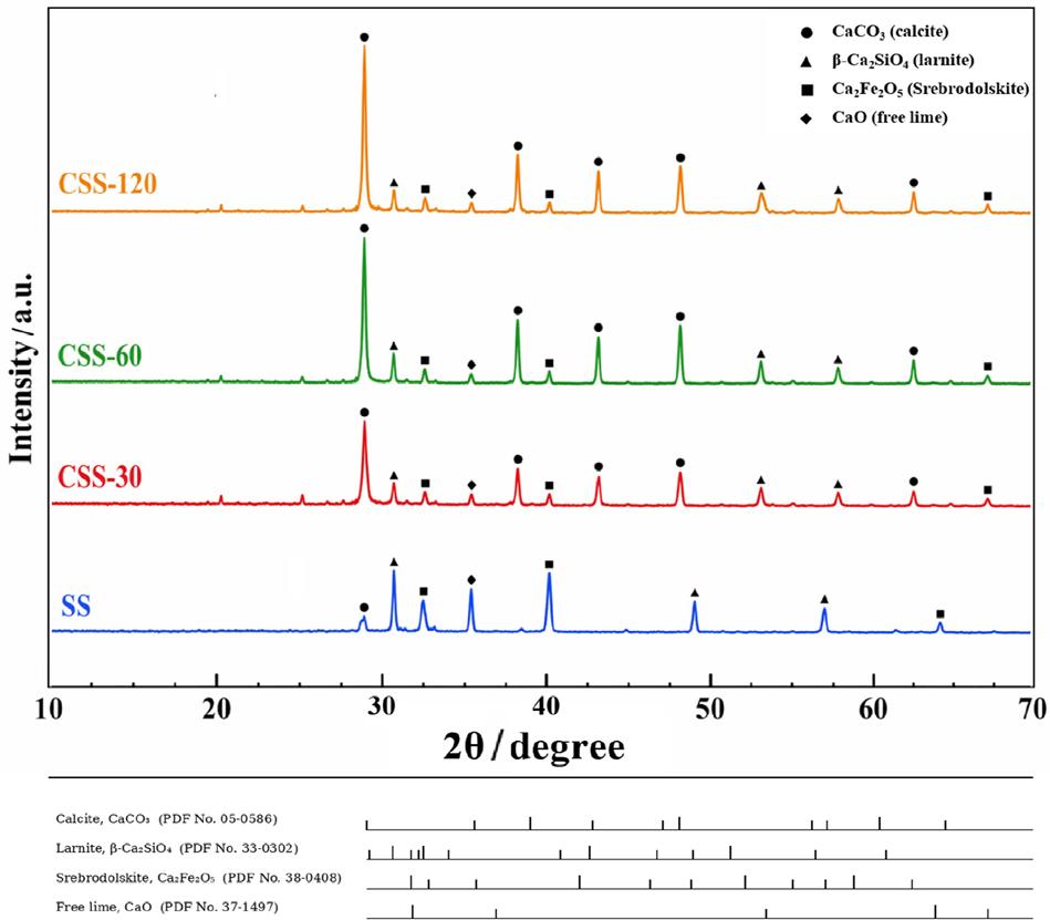
Figure 1 shows the XRD patterns of SS and mineralized slag samples with different treatment times (CSS-30, CSS 60, and CSS-120). The untreated SS exhibits reflections attributable to larnite (β-Ca2SiO4), free lime (CaO), and Fe-bearing phases, including srebrodolskite (Ca2Fe2O5). After CO2 mineralization, pronounced calcite-related reflections appear in all mineralized samples and progressively increase in relative intensity with increasing treatment time. Meanwhile, several reflections associated with the original slag phases exhibit changes in both relative intensity and apparent peak position. In particular, the variations observed above 30° should not be interpreted solely as a monotonic decrease in the intensity of the reflections associated with larnite. Since BOF slag is a multiphase material, reflections from larnite, Fe-bearing phases, free lime, and newly formed calcite may overlap in this region. Therefore, the apparent peak-position variations are more reasonably attributed to changes in the relative contributions of overlapping reflections and the emergence of calcite-related peaks during mineralization. These results qualitatively indicate that reactive Ca-bearing phases participated in the mineralization reactions and that calcite was progressively formed. Because quantitative whole-pattern fitting was not performed, the XRD results are interpreted in terms of qualitative phase-evolution trends rather than exact phase fractions or lattice-parameter variations. This is consistent with the well-established composition of SS, which is rich in Ca, Fe, Si, and Mg and contains active Ca-bearing minerals and unstable components, indicating that SS has a favorable basis for CO2 mineralization.15,18

XRD patterns of SS and mineralized slag samples with different treatment times. The reference patterns are provided for qualitative phase identification only.
From CSS-30 to CSS-60, the calcite-related reflections become more pronounced, indicating continued mineralization. When the treatment time is extended to 120 min, only limited additional changes are observed, suggesting that phase evolution gradually slows at longer treatment times. Previous studies18 have shown that free CaO, free MgO, Ca(OH)2, and part of calcium-silicate phases preferentially participate in steel slag carbonation, resulting in the formation of more stable carbonate phases and reducing slag instability and expansion risk.
The corresponding microstructural evolution is shown in Figure 2. The untreated SS sample exhibited a rough surface with irregular particle edges and localized loose or honeycomb-like regions. The corresponding textural properties were further quantitatively evaluated by N2 adsorption-desorption analysis. After CO2 mineralization, particulate deposits begin to appear on the surface of CSS 30, indicating the formation of mineralization products at the early stage. In CSS-60, the number of deposited particles increases further, and some regions exhibit a more continuous surface coverage. CSS-120 exhibits the highest surface coverage, blurred particle boundaries, and a more pronounced densified appearance. These observations indicate that carbonate products progressively deposit on particle surfaces and pore walls with increasing mineralization time, leading to surface reconstruction and a more densified surface morphology. Previous studies17 have shown that during aqueous steel slag mineralization, carbonate products are first generated on exposed active surfaces and then gradually evolve into a more continuous covering layer, thereby altering the surface morphology and pore characteristics.

SEM images of SS before and after CO2 mineralization: (a) SS, (b) CSS-30, (c) CSS-60, and (d) CSS-120.
The textural properties of SS and the mineralized SS samples are summarized in Table 2. The untreated SS exhibits a BET specific surface area of 8.43 m2 g-1, a total pore volume of 0.0237 cm3 g-1, and an average pore diameter of 11.44 nm. After CO2 mineralization, the BET specific surface area increases markedly to 15.56, 17.73, and 18.15 m2 g-1 for CSS-30, CSS-60, and CSS 120, respectively. Meanwhile, the average pore diameter progressively decreases from 11.44 nm for SS to 7.96 nm for CSS-120. These results indicate that CO2 mineralization promotes surface reconstruction and pore refinement, likely owing to the formation and deposition of fine carbonate-related products.
The total pore volume increases from 0.0237 cm3 g-1 for SS to 0.0376 cm3 g-1 for CSS-30, followed by slight decreases to 0.0364 and 0.0361 cm3 g-1 for CSS-60 and CSS-120, respectively. This trend suggests that mineralization initially generates additional accessible void space, whereas prolonged mineralization gradually induces more pronounced surface deposition and partial pore filling. Although CSS-120 exhibits the highest BET specific surface area, its slightly lower total pore volume and smaller average pore diameter indicate a more refined and partially densified pore structure. Among the mineralized samples, CSS-60 therefore provides the most favorable balance between mineralization degree and accessible porosity, which is beneficial for the subsequent distribution and confinement of molten NaNO3.
The mineralization weight gain further confirms the above trend. The weight gains of CSS-30, CSS-60, and CSS 120 are 9.37, 15.22, and 17.45%, respectively, indicating a continuous increase in CO2 uptake with prolonged mineralization. However, the increment is markedly reduced at longer times: weight gain increases by 5.85% from CSS-30 to CSS-60, but only by 2.23% from CSS-60 to CSS-120. This suggests that the reaction proceeds rapidly at the early stage but slows down substantially at the later stage. This trend is consistent with the XRD results, which show continued carbonate formation with a reduced growth rate, and the SEM results, which reveal progressively more continuous and denser surface coverage.
Based on previous studies27,28 on aqueous steel slag mineralization, the rapid initial reaction can be attributed to the abundance of exposed active sites available for CO2 fixation. As carbonate products accumulate, a denser product layer is gradually formed on the particle surface, restricting the transport of CO2, H+, and Ca2+ and causing the reaction to shift toward a product-layer diffusion-controlled regime. Therefore, the influence of CO2 mineralization on SS is clearly stage-dependent. Mineralization proceeds rapidly at the initial stage, accompanied by pronounced surface deposition, and then gradually slows as the product layer thickens.
It should also be noted that a higher degree of mineralization is not necessarily more favorable for subsequent PCM construction. Moderate mineralization helps consume unstable active phases and improve structural stability, whereas prolonged mineralization may lead to more pronounced surface deposition and pore refinement, thereby reducing the accessible void space available for the subsequent distribution and confinement of molten NaNO3.27,28 Taken together, the XRD, SEM, BET, and weight gain results indicate that CO2 mineralization alters the phase composition and surface structure of SS through a typical fast-then-slow evolution process. Among the mineralized samples, CSS-60 provides the most favorable balance between mineralization degree and accessible porosity.
Effects of mineralized slag on NaNO3 encapsulation behavior and shape stability
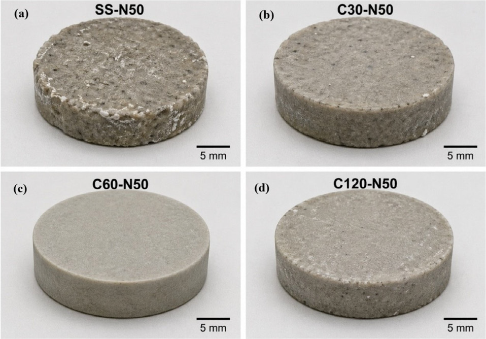
Figure 3 shows the macroscopic morphologies of composite PCMs with different mineralization degrees at a fixed NaNO3 loading of 50 wt.%. All samples maintain monolithic shapes after cold pressing and heat treatment, indicating that the slag skeleton provides sufficient macroscopic support for molten NaNO3 and helps preserve the overall sample geometry. Previous studies have shown that metallurgical-slag-based and ceramic skeletons can effectively stabilize NaNO3 through physical accommodation, capillary retention, and structural support. Qu et al.29 reported that pretreated blast furnace slag was chemically compatible with NaNO3 and could effectively stabilize a NaNO3 loading of 50 wt.%. Liu et al.8 demonstrated that steel-slag-based porous ceramics exhibited good adsorption capacity for NaNO3. Similar shape-stabilization behavior has also been observed in steel slag-carbide slag / NaNO3 composites and ceramic skeleton-supported NaNO3 systems.9

Macroscopic morphologies of composite PCMs with different mineralization degrees: (a) SS-N50, (b) C30-N50, (c) C60-N50, and (d) C120-N50.
However, the encapsulation ability and shape stability vary markedly with the mineralization degree of the slag skeleton. SS-N50 exhibits a relatively rough surface, with slight edge deformation and traces of salt exudation, indicating weak confinement of molten NaNO3 by the untreated slag skeleton. By contrast, C30-N50 shows improved integrity and reduced salt leakage, although local surface non-uniformity is still visible, suggesting that mild mineralization provides only limited improvement. C60-N50 exhibits the most intact block morphology, with a relatively smooth surface, clear edges, and no obvious deformation or leakage, indicating the best shape stability. When the mineralization time is further prolonged, C120-N50 still maintains a monolithic shape. However, its surface uniformity becomes slightly poorer than that of C60-N50, and local heterogeneity or slight salt exudation can be observed. This suggests that excessive mineralization does not provide further improvement.
These results show that CO2 mineralization affects the encapsulation behavior of NaNO3 in the SS skeleton. The relatively poor shape stability of SS-N50 is consistent with the loose morphology and unstable active components of untreated SS. After moderate mineralization, the conversion of part of the active Ca/Mg-bearing phases into more stable carbonate-related phases improves the structural stability of the skeleton. The favorable accessible porosity and rough surface morphology of CSS-60 may facilitate the distribution and confinement of molten NaNO3 within the composite structure. Similar physical stabilization behavior has been reported for metallurgical-slag-based and ceramic-skeleton-supported NaNO3 composites.8,29
Both insufficient and excessive mineralization are unfavorable for ideal encapsulation. For C30-N50, the limited degree of mineralization provides only a modest improvement in shape stability. For C120-N50, the less uniform macroscopic morphology may be associated with more pronounced surface deposition and pore refinement of CSS-120. The slightly lower total pore volume and smaller average pore diameter of CSS-120 suggest that prolonged mineralization may reduce the accessible void space available for molten NaNO3 distribution. An effective supporting matrix should therefore provide both structural stability and appropriate pore accessibility.8,11,23
Overall, the macroscopic morphologies and textural properties of the corresponding slag skeletons indicate an optimal pattern at a moderate degree of mineralization. Among the tested samples, C60-N50 exhibits the most favorable macroscopic shape stability, and CSS-60 was therefore selected as the optimal skeleton for subsequent optimization of NaNO3 loading. The photographs primarily provide macroscopic evidence of shape stability and encapsulation uniformity. The detailed evolution of the carbonate-related surface layer, the microscopic distribution of NaNO3, and the pore-filling behavior cannot be directly resolved from the macroscopic observations alone. Therefore, the proposed interpretation is based on the combined evidence from the macroscopic morphology, SEM observations of the slag skeletons, and BET results. The crystalline-phase evolution and textural changes after NaNO3 encapsulation were not directly evaluated in the present study. Further XRD and textural characterization of the encapsulated composites would be valuable for clarifying possible interfacial phase evolution and pore-filling behavior.
Thermal storage performance of composite PCMs with different NaNO3 loadings
Figure 4 shows the DSC curves of pure NaNO3 and composite PCMs (OPT-N40, OPT-N50, and OPT-N60), and the corresponding phase transition parameters are summarized in Table 3. Pure NaNO3 exhibits a typical endothermic melting peak within the tested temperature range. The corresponding onset temperature (T0), peak temperature (Tp) and ∆Hm,exp are 299.35 °C, 306.43 °C, and 175.52 J g-1, respectively, confirming its good latent heat storage capability. After shape stabilization with the mineralized SS skeleton, all composite PCMs still show clear melting endotherms, indicating that NaNO3 retains its basic phase change storage function in the composites.

In terms of phase transition temperature, the T0 values of OPT-N40, OPT-N50, and OPT-N60 are 297.90, 298.21, and 298.63 °C, respectively, and the corresponding Tp values are 305.04, 305.36 and 305.82 °C. Compared to pure NaNO3, the phase transition temperatures of the composites decrease only slightly and gradually approach those of pure NaNO3 with increasing NaNO3 loading. This suggests that the mineralized SS skeleton has only a limited effect on the phase transition process of NaNO3 and that the thermal response of the composites is still dominated by NaNO3. The slightly lower phase transition temperatures at low loading may be associated with stronger confinement by the skeleton, restricted crystallization, and reduced crystal perfection due to interfacial interactions. With increasing NaNO3 content, the confinement effect becomes relatively weaker, so the phase transition peaks shift closer to those of pure NaNO3. Similar trends have been reported30,31 for other NaNO3-based composite PCMs, where the supporting skeleton generally does not significantly alter the phase transition window of NaNO3 but does affect peak shape, crystallization behavior, and phase transition completeness.
The ∆Hm,exp values of OPT-N40, OPT-N50, and OPT-N60 are 67.43, 83.22, and 97.38 J g-1, respectively, indicating a continuous increase in thermal storage capacity as the NaNO3 loading increases from 40 to 60 wt.%. This behavior is typical of shape-stabilized composite PCMs, in which the effective latent heat storage capacity mainly depends on the actual PCM content. The corresponding latent heat utilization ratios are 96.04, 94.83, and 92.47% for OPT-N40, OPT-N50, and OPT-N60, respectively. The experimental melting enthalpies are lower than the theoretical values by 2.78, 4.54, and 7.93 J g-1, corresponding to relative deviations of 3.96, 5.17, and 7.53%, respectively. Therefore, the deviation is not equally small for all samples and becomes more pronounced as the NaNO3 loading increases, particularly for OPT-N60. This trend suggests that, at higher salt loadings, part of the NaNO3 may not be uniformly distributed within the accessible void space of the supporting skeleton, and its crystallization may be more strongly affected by local confinement and interfacial interactions. Similar deviations between experimental and theoretical enthalpy have been widely reported30,32 in NaNO3-based shape-stabilized systems.
Although OPT-N60 exhibits the highest absolute melting enthalpy, its larger deviation from the theoretical value indicates that the effective confinement capacity of the mineralized slag skeleton is being approached at a NaNO3 loading of 60 wt.%. By contrast, OPT-N50 provides a more favorable balance between latent heat storage capacity and encapsulation stability.
The slight decrease in ηH with increasing NaNO3 loading further indicates that the effective loading capacity of the skeleton is gradually approached. Higher salt loading increases the storage density but also places greater demands on encapsulation uniformity and long-term reliability.33,34 Considering the phase transition temperatures, enthalpy values, and shape stability, OPT-N50 provides the most favorable balance between storage capacity and encapsulation stability and was therefore selected for further thermal-stability and cycling-stability analyses.
Thermal stability and thermal conductivity of the composite PCMs
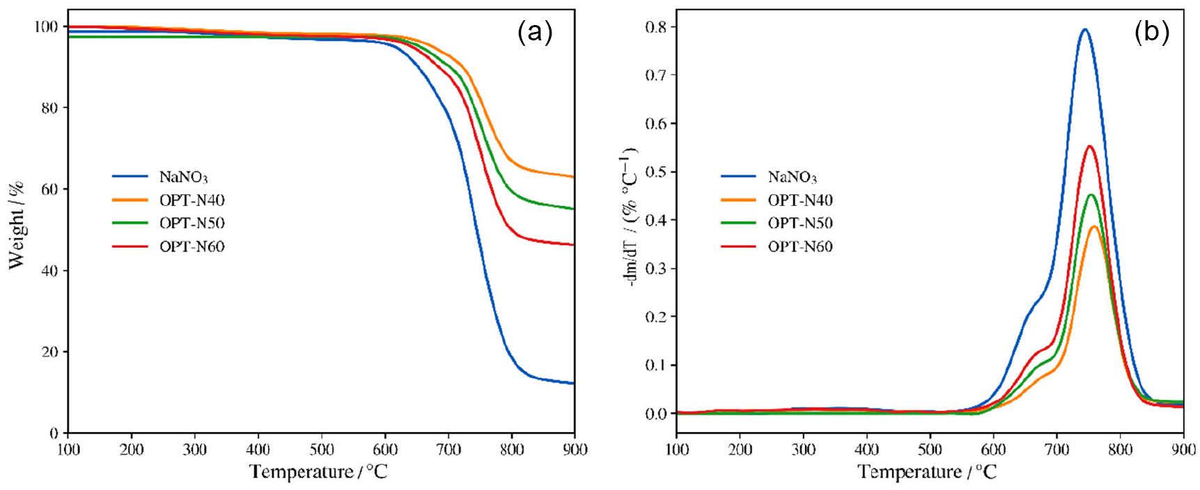
Figure 5 shows the TG and DTG curves of pure NaNO3 and the composite PCMs with different NaNO3 loadings. As shown in Figure 5a, pure NaNO3 and the composite PCMs exhibit only limited mass changes below 500 °C. The differences among the samples in this temperature range are modest rather than pronounced, indicating that all samples remain relatively stable within the intended operating temperature range. Above approximately 600 °C, the samples undergo more evident mass loss. Pure NaNO3 shows the largest mass loss and retains approximately 14.71% of its initial mass at 900 °C. By contrast, the residual masses of OPT-N40, OPT-N50, and OPT-N60 are approximately 64.59, 56.21, and 47.85%, respectively. The higher residual masses of the composite PCMs are mainly associated with the presence of the inorganic slag skeleton.

The DTG curves in Figure 5b provide a clearer distinction among the high-temperature mass-loss processes. Pure NaNO3 exhibits a pronounced DTG peak at approximately 744.26 °C, corresponding to its rapid decomposition at high temperature. After incorporation into the mineralized slag skeleton, the DTG peaks shift slightly toward higher temperatures. The peak temperatures of OPT-N40, OPT-N50, and OPT-N60 are approximately 758.37, 754.63, and 752.24 °C, respectively. Meanwhile, the maximum mass-loss rate decreases markedly after the introduction of the slag skeleton. Among the composite PCMs, the DTG peak intensity increases progressively with increasing NaNO3 loading, following the order OPT-N40 < OPT-N50 < OPT-N60. This trend is consistent with the increasing contribution of nitrate decomposition at higher PCM loadings.
The higher residual masses of the composite PCMs are mainly associated with the inorganic slag fraction. The slag skeleton may also reduce local migration and volatilization of molten NaNO3 to some extent. However, carbonate-related phases formed during mineralization may decompose at elevated temperatures. Therefore, the TG and DTG features at high temperature should be interpreted as the combined result of the inorganic skeleton fraction, nitrate decomposition, and possible carbonate decomposition.
As expected, the residual mass increases with increasing skeleton fraction. OPT-N40 retains the highest residual mass because it contains the largest proportion of inorganic skeleton. OPT-N40 shows the highest thermal stability owing to its highest skeleton content, whereas OPT-N60, despite its higher PCM content, exhibits the lowest residual mass, indicating that systems with high salt loading rely more strongly on the continuity of the supporting skeleton. This trend is consistent with previous studies35,36 showing that the introduction of porous supports or skeletons improves the thermal stability of nitrate-based composite systems and lowers leakage risk.
Table 4 summarizes the thermal conductivity values (λ) of pure NaNO3 and the composite PCMs at 100, 200, and 340 °C. All samples show a monotonic decrease in λ with increasing temperature, whereas all composite PCMs remain significantly more conductive than pure NaNO3 throughout the tested range. For pure NaNO3, the thermal conductivity decreases with increasing temperature because elevated temperatures weaken lattice ordering and hinder phonon transport. When approaching and entering the molten state, the liquid-phase heat transfer pathway becomes less efficient, resulting in relatively low thermal conductivity.35 By contrast, the slag skeleton in the composite PCMs provides not only structural support but also a relatively continuous heat-conducting network, which markedly enhances λ relative to pure salt.30,33,36 In addition, as the NaNO3 loading increases from 40 to 60 wt.%, the fraction of the solid skeleton decreases, weakening the continuity of the conductive network. As a result, the thermal conductivity follows the order OPT-N40 > OPT-N50 > OPT-N60. Similar behavior has also been reported in other NaNO3-based composites. Lyu et al.30 demonstrated that graphene nanosheets significantly enhance the thermal conductivity of NaNO3 composites and attributed the effect to interfacial vibration matching and the formation of continuous conductive pathways. Suthan et al.37 also found that ZnO-NaNO3 nanocomposites show higher thermal conductivity than pure NaNO3 at 200 °C without markedly altering the onset or peak melting temperatures. These observations indicate that the thermal conductivity of composite PCMs depends not only on the conductivity of the skeleton/filler itself but also on interfacial structure and the connectivity of the conductive network.
The results indicate that different NaNO3 loadings lead to distinct trade-offs between storage capacity, thermal stability, and heat transfer performance. OPT-N40 exhibits the highest λ and the highest high-temperature residual mass, indicating superior structural stability and heat transfer capability, but its thermal storage capacity is limited by the lowest NaNO3 content. By contrast, OPT-N60 provides a higher ∆Hm,exp at the expense of part of its thermal stability and heat transfer performance. OPT-N50 offers the best compromise among latent heat storage capacity, thermal stability, and thermal conductivity. Combined with the encapsulation behavior and thermal storage results discussed above, OPT-N50 can be regarded as the optimum sample in terms of overall performance, whereas OPT-N40 may be preferred in scenarios where thermal safety and rapid heat transfer are prioritized.
Microstructure and cycling stability
Figure 6 shows the SEM images of composite PCMs with different NaNO3 loadings before and after 300 thermal cycles. Before cycling, the mineralized SS skeleton exhibits a distinct porous and rough structure, and NaNO3 appears to occupy pores and interparticle gaps while remaining in close contact with the skeleton surface. As the NaNO3 loading increases, the amount of exposed skeleton decreases and the salt coverage becomes progressively higher. OPT-N40 shows more exposed skeleton regions, indicating a relatively low salt loading and better pore retention. OPT-N60, on the other hand, exhibits a higher salt coverage and a stronger tendency for local salt enrichment. OPT-N50 exhibits a relatively homogeneous apparent salt distribution and a more uniform skeleton-salt interface. Similar microstructural features have also been reported in other NaNO3-based shape-stabilized composite PCMs, where moderate salt loading is generally more favorable for obtaining uniform salt distribution and a stable skeleton-salt interfacial structure.38,39

SEM images of composite PCMs before and after 300 thermal cycles: (a) OPT-N40 before cycling, (b) OPT-N50 before cycling, (c) OPT-N60 before cycling, (d) OPT-N40 after cycling, (e) OPT-N50 after cycling, and (f) OPT-N60 after cycling.
After 300 cycles, the overall morphology of the composite PCMs remains largely intact, and no obvious large-scale disruption of the skeleton structure is observed. Only slight blunting of local edges, surface smoothing, and minor redistribution of the salt phase can be identified. These observations indicate that the mineralized SS skeleton provides effective macroscopic support and morphological confinement for NaNO3 during repeated melting and solidification. However, the SEM images provide morphological evidence at the microscale and should not be interpreted as direct evidence that the crystalline phases remain completely unchanged after thermal cycling. Previous studies40 have shown that NaNO3 based shape-stabilized composite PCMs can maintain good chemical compatibility, structural stability, and thermal performance after repeated thermal cycling, whereas significant performance degradation is usually associated with interfacial debonding, localized salt accumulation, and aggravated structural heterogeneity.
To quantitatively evaluate the cycling stability, the phase transition parameters after 300 cycles are summarized in Table 5. In general, all samples exhibit only small decreases in T0 and Tp after cycling, and the DH remains below 5%, indicating good thermal cycling stability. OPT-N50 shows the smallest variation, with T0 and Tp decreasing by only 0.16 and 0.12 °C, respectively, and ∆Hm reaching 80.83 J g-1, corresponding to a DH value of 2.87%. By comparison, OPT-N40 shows a DH value of 3.72%, while OPT-N60 shows the largest variation, with T0 and Tp decreasing by 0.41 and 0.31 °C, respectively, and ∆Hm decreasing to 92.81 J g-1, corresponding to a DH value of 4.69%. These results indicate that the cycling stability of the composites is governed not by the skeleton fraction or PCM content alone, but by their combined effect.
For OPT-N40, the relatively high skeleton fraction helps maintain structural integrity and suppress molten salt migration, but the lower effective PCM fraction increases the relative proportion of interfacial regions in the overall system, thereby making interfacial constraint on latent heat release more pronounced and resulting in a slightly higher DH value than that of OPT-N50. For OPT-N60, the higher NaNO3 loading increases the initial thermal storage capacity but also brings the skeleton confinement ability closer to its limit. As a result, local salt accumulation, interfacial redistribution, and microstructural heterogeneity are more likely to develop during thermal cycling, leading to more evident phase transition temperature drift and enthalpy loss. In contrast, OPT-N50 provides a more favorable balance among skeleton continuity, salt distribution uniformity, and storage capacity and thereby exhibiting the smallest parameter variation and the best thermal reliability.40,41
The observed cycling stability may be associated with the physical confinement provided by the mineralized SS skeleton and the preservation of morphological integrity during repeated melting and solidification. An appropriate skeleton fraction is important for balancing storage density and structural stability, whereas excessively low or high NaNO3 loading may increase interfacial constraints or local salt-rich regions during cycling. Previous studies41 have identified pore structure, wettability, supporting-network continuity, and interfacial compatibility as important factors influencing the long-term cycling stability of shape-stabilized composite PCMs.
Overall, the mineralized SS skeleton helps preserve the morphological integrity and thermal reliability of the NaNO3 composite PCMs during repeated melting and solidification. After 300 thermal cycles, the samples retain relatively stable macroscopic and microscopic morphologies, while the shifts in phase transition temperatures remain below 0.5 °C and the enthalpy decay values remain below 5%. Among the investigated samples, OPT-N50 exhibits the smallest parameter variations and therefore provides the most favorable balance among salt loading, morphological stability, and thermal cycling reliability.
Conclusions
CO2 mineralization effectively converted SS into a stable supporting skeleton for NaNO3 shape-stabilized composite PCMs by promoting carbonate formation, weakening the original active phases, and increasing the weight gain from 9.37 to 17.45% as the treatment time increased from 30 to 120 min. Among the mineralized samples, CSS-60 showed the most favorable balance between mineralization degree and accessible porosity. Using CSS-60 as the skeleton, the composite PCMs exhibited improved encapsulation behavior and shape stability, while their ∆Hm,exp increased with NaNO3 loading, reaching 67.43, 83.22, and 97.38 J g-1 for OPT-N40, OPT-N50, and OPT-N60, respectively. Compared to pure NaNO3, the composites showed enhanced thermal stability and higher thermal conductivity. After 300 thermal cycles, all samples maintained good cycling stability, with shifts in T0 and Tp below 0.5 °C and DH values below 5%. Among the investigated samples, OPT-N50 delivered the best overall balance between latent heat storage capacity, structural stability, heat transfer performance, and cycling reliability. These results demonstrate that CO2-mineralized SS is a promising low-cost and low-carbon supporting matrix for medium-temperature latent heat storage materials.
Acknowledgments
The authors gratefully acknowledge the financial support provided by the Science and Technology Research Program of Chongqing Municipal Education Commission under grant No. KJQN202502603 and KJQN202502602.
Data Availability Statement
All data are available in the text. This manuscript only uses artificial intelligence tools (Doubao (ByteDance), Seed 2.0 Pro version) for language editing and grammatical polishing. The final wording and content have been reviewed and approved by all authors.
References
-
1 Wang, H.; Liu, J.; Wang, Y.; Zhao, Y.; Zhang, G.; Appl. Energy 2025, 389, 125766. [Crossref]
» Crossref -
2 Ong, T. C.; Sarvghad, M.; Bell, S.; Will, G.; Steinberg, T. A.; Yin, Y.; Andersson, G.; Lewis, D.; Appl. Therm. Eng. 2024, 238, 122034. [Crossref]
» Crossref -
3 Hamzat, A. K.; Pasanaje, A. H.; Omisanya, M. I.; Sahin, A. Z.; Maselugbo, A. O.; Adediran, I. A.; Mudashiru, L. O.; Asmatulu, E.; Oyetunji, O. R.; Asmatulu, R.; J. Energy Storage 2025, 114, 115762. [Crossref]
» Crossref -
4 Prieto, C.; Borri, E.; Pavon-Moreno, M. C.; Zsembinszki, G.; Cabeza, L. F.; Appl. Therm. Eng. 2025, 275, 126823. [Crossref]
» Crossref -
5 Xu, G.; Leng, G.; Yang, C.; Qin, Y.; Wu, Y.; Chen, H.; Cong, L.; Ding, Y.; Sol. Energy 2017, 146, 494. [Crossref]
» Crossref -
6 Soleimanpour, S.; Sadrameli, S. M.; Mousavi, M.; Jafaripour, M.; J. Energy Storage 2022, 45, 103735. [Crossref]
» Crossref -
7 Grégoire, B.; Ma, H.; Palacios, A.; Yang, S.; Bai, M.; Zhang, T.; Ding, Y.; J. Energy Storage 2024, 101, 113922. [Crossref]
» Crossref -
8 Liu, K.; Yuan, Z.; Zhao, H.; Xu, B.; Lu, Y.; Zhang, H.; Ma, B.; Ceram. Int. 2023, 49, 35466. [Crossref]
» Crossref -
9 Xiong, Y.; Yang, Y.; Zhang, A.; Ren, J.; Xu, Q.; Wu, Y.; Zhao, Y.; Ding, Y.; J. Energy Storage 2024, 76, 109736. [Crossref]
» Crossref -
10 Xiong, Y.; Zhang, A.; Yang, Y.; Ren, J.; He, M.; Wu, Y.; Zhang, C.; Ding, Y.; Renewable Energy 2024, 235, 121251. [Crossref]
» Crossref -
11 Liu, W.; Zhang, S.; Yang, L.; Li, B.; J. Energy Storage 2024, 94, 112426. [Crossref]
» Crossref -
12 Lu, Y.; Liu, K.; Yuan, Z.; Zhao, H.; Xu, B.; J. Energy Storage 2025, 113, 115622. [Crossref]
» Crossref -
13 Wu, B.; Chen, G.; Di, Y.; Liu, J.; Zhang, X.; Jiao, K.; Wu, L.; Wei, Y.; Lin, L.; Jiang, Z.; Zhang, X.; Ceram. Int. 2024, 50, 46932. [Crossref]
» Crossref -
14 Yang, C.; Yu, H.; Zhang, Z.; Rui, Z.; Chu, H.; Ceram. Int. 2025, 51, 22209. [Crossref]
» Crossref -
15 Naidu, T. S.; Sheridan, C. M.; van Dyk, L. D.; Miner. Eng. 2020, 149, 106234. [Crossref]
» Crossref -
16 Zhang, X.; Zhao, J.; Liu, Y.; Li, J.; J. CO2 Util. 2024, 88, 102947. [Crossref]
» Crossref -
17 DiGiovanni, C.; Hisseine, O. A.; Awolayo, A. N.; J. CO2 Util. 2024, 81, 102736. [Crossref]
» Crossref -
18 Wang, S.; Wang, M.; Liu, F.; Song, Q.; Deng, Y.; Ye, W.; Ni, J.; Si, X.; Wang, C.; Materials 2024, 17, 2066. [Crossref]
» Crossref -
19 Huang, X.; Zhang, J.; Zhang, L.; Constr. Build. Mater. 2024, 411, 134603. [Crossref]
» Crossref -
20 Biava, G.; Depero, L. E.; Bontempi, E.; Spanish J. Soil Sci. 2024, 14, 12908. [Crossref]
» Crossref -
21 Liu, Y.; Jiang, Z.; Zhang, X.; Wu, B.; Shen, Y.; Wu, L.; Zhang, X.; Mater. Chem. Phys. 2023, 301, 127655. [Crossref]
» Crossref -
22 Liu, J.; Su, Z.; Xu, J.; Zhang, Y.; Jiang, T.; Ceram. Int. 2023, 49, 38094. [Crossref]
» Crossref -
23 Jiang, F.; Ge, Z.; Ling, X.; Cang, D.; Zhang, L.; Ding, Y.; Renewable Energy 2021, 179, 327. [Crossref]
» Crossref -
24 Li, C.; Li, Q.; Ge, R.; Energy Rep. 2022, 8, 12740. [Crossref]
» Crossref -
25 Wang, Q.; Wu, C.; Wang, X.; Sun, S.; Cui, D.; Pan, S.; Sheng, H.; Int. J. Heat Mass Transfer 2023, 205, 123904. [Crossref]
» Crossref -
26 Li, Y. R.; Liao, H. Q.; Guo, Y. X.; J. Environ. Chem. Eng. 2025, 13, 115951. [Crossref]
» Crossref -
27 Zhang, N. N.; Deng, G.; Liao, W. Y.; Ma, H.; Hu, C.; Cem. Concr. Compos. 2025, 155, 105838. [Crossref]
» Crossref -
28 Tu, M.; Zhao, H.; Lei, Z.; Wang, L.; Chen, D.; Yu, H.; Qi, T.; ISIJ Int. 2015, 55, 2509. [Crossref]
» Crossref -
29 Qu, A.; Zhao, J.; Peng, H.; Jiang, F.; J. Energy Storage 2022, 55, 105870. [Crossref]
» Crossref -
30 Lyu, H.; Feng, D.; Feng, Y.; Zhang, X.; J. Energy Storage 2022, 54, 105294. [Crossref]
» Crossref -
31 Li, C.; Han, L.; Li, Q.; Leng, G.; Lu, H.; Xu, R.; Du, Y.; Wu, Y.; Sol. Energy Mater. Sol. Cells 2024, 271, 112821. [Crossref]
» Crossref -
32 Liu, J.; Xu, J.; Su, Z.; Zhang, Y.; Jiang, T.; Sol. Energy Mater. Sol. Cells 2023, 251, 112114. [Crossref]
» Crossref -
33 Díaz-Herrezuelo, I.; Moreno-Sanabria, L.; Miranzo, P.; Osendi, M. I.; Belmonte, M.; Addit. Manuf. 2022, 59, 103108. [Crossref]
» Crossref -
34 Diaz-Herrezuelo, I.; Miranzo, P.; Osendi, M. I.; Belmonte, M.; J. Energy Storage 2024, 85, 111108. [Crossref]
» Crossref -
35 Svobodova-Sedlackova, A.; Huete-Hernández, S.; Calderón, A.; Barreneche, C.; Gamallo, P.; Fernandez, A. I.; Nanomaterials 2022, 12, 1777. [Crossref]
» Crossref -
36 Zhao, C. Y.; Wu, Z. G.; Sol. Energy Mater. Sol. Cells 2011, 95, 636. [Crossref]
» Crossref -
37 Suthan, V. H.; Suganthi, K. S.; Rajan, K. S.; Sci. Rep. 2024, 14, 23619. [Crossref]
» Crossref -
38 Yang, H.; Zhang, W.; Zhu, Y.; Shao, Y.; Shao, Y.; Zhang, X.; J. Energy Storage 2022, 56, 106047. [Crossref]
» Crossref -
39 Wang, X.; Deng, J.; Zhang, W.; Shao, Y.; Zhang, T.; Liu, S.; Yu, S.; Zhang, S.; Zhu, Y.; J. Energy Storage 2024, 103, 114341. [Crossref]
» Crossref -
40 Wang, X.; Zhang, W.; Shao, Y.; Zhang, T.; Shao, Y.; Tian, C.; Ma, J.; Yang, Y.; Chu, L.; Zhu, Y.; J. Energy Storage 2024, 76, 109810. [Crossref]
» Crossref -
41 Zhang, S.; Li, Z.; Yao, Y.; Tian, L.; Yan, Y.; Nano Energy 2022, 100, 107476. [Crossref]
» Crossref
Edited by
-
Editor handled this article:
Juliano Alves Bonacin (Associate)